EP0884236A2 - Dispositif de montage - Google Patents
Dispositif de montage Download PDFInfo
- Publication number
- EP0884236A2 EP0884236A2 EP98110040A EP98110040A EP0884236A2 EP 0884236 A2 EP0884236 A2 EP 0884236A2 EP 98110040 A EP98110040 A EP 98110040A EP 98110040 A EP98110040 A EP 98110040A EP 0884236 A2 EP0884236 A2 EP 0884236A2
- Authority
- EP
- European Patent Office
- Prior art keywords
- rope
- clamping
- screw
- opening
- fastening device
- Prior art date
- Legal status (The legal status is an assumption and is not a legal conclusion. Google has not performed a legal analysis and makes no representation as to the accuracy of the status listed.)
- Granted
Links
- 238000003780 insertion Methods 0.000 claims description 9
- 230000037431 insertion Effects 0.000 claims description 9
- 238000007373 indentation Methods 0.000 claims description 8
- 239000002184 metal Substances 0.000 claims description 7
- 230000008719 thickening Effects 0.000 claims description 7
- 230000035622 drinking Effects 0.000 claims 1
- 230000004913 activation Effects 0.000 abstract 1
- 230000008901 benefit Effects 0.000 description 5
- 238000000034 method Methods 0.000 description 4
- 230000008569 process Effects 0.000 description 4
- 230000008878 coupling Effects 0.000 description 2
- 238000010168 coupling process Methods 0.000 description 2
- 238000005859 coupling reaction Methods 0.000 description 2
- 238000006073 displacement reaction Methods 0.000 description 2
- 230000000694 effects Effects 0.000 description 2
- 238000013459 approach Methods 0.000 description 1
- 230000009286 beneficial effect Effects 0.000 description 1
- 230000008859 change Effects 0.000 description 1
- 238000010276 construction Methods 0.000 description 1
- 238000009434 installation Methods 0.000 description 1
- 230000003993 interaction Effects 0.000 description 1
- 238000004519 manufacturing process Methods 0.000 description 1
- 230000002093 peripheral effect Effects 0.000 description 1
- 238000003825 pressing Methods 0.000 description 1
- 230000009467 reduction Effects 0.000 description 1
- 238000004904 shortening Methods 0.000 description 1
- 238000003860 storage Methods 0.000 description 1
- XLYOFNOQVPJJNP-UHFFFAOYSA-N water Substances O XLYOFNOQVPJJNP-UHFFFAOYSA-N 0.000 description 1
Images

Classifications
-
- B—PERFORMING OPERATIONS; TRANSPORTING
- B62—LAND VEHICLES FOR TRAVELLING OTHERWISE THAN ON RAILS
- B62H—CYCLE STANDS; SUPPORTS OR HOLDERS FOR PARKING OR STORING CYCLES; APPLIANCES PREVENTING OR INDICATING UNAUTHORIZED USE OR THEFT OF CYCLES; LOCKS INTEGRAL WITH CYCLES; DEVICES FOR LEARNING TO RIDE CYCLES
- B62H5/00—Appliances preventing or indicating unauthorised use or theft of cycles; Locks integral with cycles
- B62H5/003—Appliances preventing or indicating unauthorised use or theft of cycles; Locks integral with cycles using chains or cables
Definitions
- the invention relates to a fastening device with which especially a rope end on a moving object in can be attached in such a way that unauthorized loosening of the rope end is prevented by the object.
- Such fastening devices are required, for example, around one end of a cable lock firmly with a two-wheeler to connect or two mobile in the construction machinery area Coupling objects with each other in an unsolvable manner.
- An object of the invention is a fastening device of the type mentioned in such a way that they is simple and easy to assemble, in particular also the highest possible security against an unauthorized Guaranteed loosening of the fastening device after its assembly should be.
- this object is achieved by a fastening device with a sprag, in which a Cable end is attachable, one is provided in the clamping body Through opening for a spaced from the rope end Clamping section of the rope and one in the area of the through opening Clamping screw that can be screwed into the clamping body Acting on the clamping section, being between the rope end and clamping section one by tightening the clamping screw shortenable rope loop can be formed.
- This arrangement according to the invention enables a simple one Assembly of the fastening device, for example on a Frame tube of a two-wheeler:
- the rope is attached to the end of the frame tube pushed ahead through the through opening of the sprag, placed in a loop around the frame tube and then on the clamp body, for example by means of a screw connection attached.
- the clamp body and Rope loop is a loose but complete frame tube surrounding unit.
- pull on the rope in such a way that the rope loop encloses the frame tube as tightly as possible, whereupon the clamping screw is screwed into the clamping body is, in this way, the one located in the clamping body Apply clamping section of the rope so that shortens the rope loop surrounding the frame tube and by Frame tube is tightened.
- the clamping body is firmly connected to the frame tube.
- connection necessary to close the rope end through the through opening thread and then connect to the clamp body, whereupon only the clamping screw has to be tightened.
- the assembly process is therefore very simple, in particular because the length of the thread to be threaded through the through hole Rope section on the distance between the rope end and Clamping section of the rope is limited. Often clearly longer area of the rope, which is on the said rope end side of the clamping section facing away from this, does not have to go through the through opening according to the invention be threaded.
- the end of the rope with a Be internally threaded screw sleeve.
- the end of the rope is, for example, by means of a fastening screw, which can be screwed into the screw-on sleeve can be fastened in the clamp body.
- the clamping screw for tightening the rope loop is preferred trained as a grub screw that in its tightened Condition in particular completely included in the clamping body is. This enables a largely smooth surface of the clamping body, which have no annoying approaches or screw heads having.
- the thread receiving the clamping screw preferably extends essentially perpendicular to that provided in the clamping body Through opening, because in this way a special effective clamping effect can be achieved. It stretches the thread receiving the clamping screw from the outside of the clamping body into the through opening, so that the clamping screw on the one hand from the outside of the clamping body accessible, for example, using an Allen key is and on the other hand an application of the in the through opening located clamping section of the rope allows becomes.
- the free cross section of the through opening of the clamping body formed larger at least in the area of the clamping screw be than the rope diameter.
- The is preferably called free cross-section a multiple of the rope diameter in the direction of the thread receiving the clamping screw. So the clamping screw can move the maximum Clamping section of the rope and thus a maximum shortening the rope loop.
- the rope can, for example, as with a commercially available Cable lock have a plastic-coated metal core.
- any other stable embodiment is also the same of the rope can be realized.
- the clamping body in the through opening provided extending web, the longitudinal direction at least essentially parallel to the clamping screw receiving thread runs. Particularly preferred it is when two such clamping webs face each other are arranged in the interior of the through opening.
- the clamping webs mentioned press during the clamping process or while tightening the clamping screw in the outer peripheral portion of the clamping portion of the rope, whereby the rope slips out during the clamping process from the clamp body in the sense of an unwanted enlargement the rope loop is prevented.
- the effect of the clamping bars can be achieved when the outside area the rope, for example from a plastic cover consists. In this case, the clamping webs can Press in the plastic cover.
- the mutual distance of two opposing clamping webs like this chosen to be slightly larger than the diameter of the metal core of the rope.
- the rope end can also have a thickening, in particular be connected to a block whose diameter is larger than the rope diameter, the clamping body one Has insertion recess for a fork part, the fork space is adapted to the rope diameter.
- the end of the rope can be pushed into the clamping body until the thickening behind the area of the insertion recess comes to rest, whereupon the fork part is inserted and a thickening in its space between the forks adjacent rope area. The fork part prevents in this position moving the rope end out from the clamp body.
- the fork part is at least essentially perpendicular to the rope in its adjacent to the thickening Area extends.
- the fork part can, for example be held with a press fit in the insertion recess, so that it is, for example, after driving into the insertion recess no more or only under the operation of a substantial Effort can be solved by the clamp body.
- the clamping body is one of the rope loops Has facing indentation, which in particular adapted the diameter of a frame tube of a two-wheeler is. In this way it is achieved that the clamping body and rope loop surround the frame tube in a form-fitting manner, resulting in a leads to a particularly good hold.
- the clamping body can be a holding section for two-wheeler accessories, such as locks, water bottles, Have child seats, bags and the like.
- the holding section for holding a bracket or The padlock should be suitable, it can be two opposite one another Indentations for receiving the two arm legs have. So a closed bracket or Padlock in its closed state firmly with the holding section of the sprag can be connected.
- the other end of the rope, which is not connected to the clamp body is or which is not within the sprag with the lock body of a locking device, e.g. a padlock, padlock or rope lock can be coupled.
- a locking device e.g. a padlock, padlock or rope lock
- this other end of the rope another screw-on sleeve, also with an internal thread having. If there is a bracket opening of the Lock body of a U-lock designed as a through hole is, the further screw sleeve and thus that the other end of the rope by means of a bracket in the through hole insertable screw connected to the lock body will. The screw is thus in the same direction in the Bow opening inserted, like the bow when closing the Castle and that with the lock body in the manner mentioned coupled rope emerges from the through hole Bracket opening on the side of the bracket facing away from the bracket Lock body from this.
- the other can Rope end can also be connected to a rope lock or in a pass over the lockable loop. It is an advantage if the lockable loop can be changed in scope is, so that depending on the application by the user The size of the loop can be adjusted.
- the lockable Loop formed by means of a clamping and closing body, which is a lock for locking the respective rope end and a clamping device for one spaced from the respective end Has area of the rope, the loop between said rope end and the one spaced from it Area is formed.
- the clamping device is designed in this way is that the rope is taking advantage of the through its Self-curvature caused forces between at least three bearing points can be pinched.
- This variant is special Advantage because of the scope of the lockable loop in this case without any tools just by twisting and moving the rope or the clamping device can be changed.
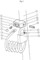
- Fig. 1 shows a clamp body 1, which in plan view essentially a trapezoidal shape with indentations having.
- the clamping body 1 is provided with a through hole 2, which have a substantially rectangular cross section (see 3) which is located in the course of the passage opening 2 enlarged or reduced, as indicated by the dashed lines Lines B of FIG. 1, which delimit the passage opening 2, is illustrated.
- the clamping body 1 is with a Provide another hole 3. Starting from that end of the clamping body 1, at which the through opening 2 has the largest Has cross section, the further bore 3 in one first section a first, larger diameter, in one followed by a second, smaller section Diameter and then in a third section again a larger diameter so that ultimately a step-like diameter course over the length of the Hole 3 results.
- the outer diameter of the screw sleeve 4 is slightly smaller than the diameter of the bore 3 in the first section, so that a easy insertion of the screw-on sleeve 4 in the section mentioned the hole 3 is possible.
- the screw-on sleeve 4 On its side facing away from the rope end 5 is the screw-on sleeve 4 provided with an internal thread 6 into which a fastening screw 7 can be screwed in.
- the diameter of the Screw head of the mounting screw 7 is larger than that second section of the bore 3, which is opposite to the first section has a reduced diameter. Consequently can by screwing the mounting screw 7 into the Screw-on sleeve 4 fixing the same in the bore 3 respectively.
- the third, again with a larger diameter Section of bore 3 is deeper than the depth of the screw head the mounting screw 7 formed so that there is still enough space above the screw head remains for pressing or driving in a plug 8.
- the plug 8 is thus a press fit in the third section the bore 3 is held and prevents access to the screw head of the screwed into the screw-on sleeve 4 Fixing screw 7.
- the end of the bore 3 facing away from the plug 8 the clamping body 1 protruding rope 9 forms a loop around a frame tube 10 of a two-wheeler and is connected to the Loop subsequent clamping section 11 through the through hole 2 passed through.
- a thread 12 extends through the through opening 2 the section of the clamping body 1 facing away from the bore 3.
- this thread 12 is a serving as a clamping screw 13 Screwed in grub screw facing away from the Allen 14 End 15 acts on the clamping section 11 of the rope 9 or clamped in the through opening 2.
- Clamping webs 16 are provided, the longitudinal direction of which is parallel to the the clamping screw 13 receiving thread 12 runs.
- the Clamping webs 16 are on the side facing away from the frame tube 10 of the thread 12 arranged, the extension of the Clamping webs 16 on an area of the bore 3 Through opening 2 limited. In a bore 3 facing away A region of the through opening 2 thus exists area free of the terminal bridge.
- Fig. 2 shows a section along the section line A-A accordingly Fig. 1.
- This sectional view shows that the rope 9 with a a plastic sheath 17 provided metal core 18.
- the inner surface of the through opening 2 two opposite each other, in the through hole 2 has clamping webs 16 extending into it, which are pressed into the plastic sheath 17 of the rope 9 and this with reference to D in FIG. 2 Inhibit direction of movement.
- the through opening 2 shown in Fig. 2 has a in the direction of the imaginary connecting line of the two clamping webs 16 enlarged cross section on the frame tube 10 facing side.
- the clamping webs 16 On the side facing away from the frame tube 10 the clamping webs 16 has a through opening 2 reduced cross-section, which in the direction of the connecting line of the two clamping webs 16 only slightly larger is the total diameter of the rope 9.
- the clamping screw 13 shown in dashed lines in FIG. 2 illustrates that the clamping webs 16 on the frame tube 10 facing away from the clamping screw 13.
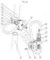
- FIGS. 1 and 2 shows an exploded view the arrangement of FIGS. 1 and 2 with sprags 1, frame tube 10, fastening screw 7, plug 8, Clamping screw 13 and rope 9 arranged at the rope end 5 Screw-on sleeve 4.
- the rope 9 is designed as a spiral cable and is on his other end facing away from the rope end 5 with a padlock 19 coupled.
- the padlock 19 is of a conventional design with the difference that that the bracket opening 20 is formed as a through hole is so that from below into the through hole the other Rope end with a screw-on sleeve not recognizable in FIG. 3 be introduced and by means of a from above in the through hole inserted screw fixed in this can be.
- the rope end 5 with screw sleeve 4 is through the through hole 2 of the clamping body 1 in the direction of arrow E. threaded and placed in a loop around the frame tube 10. Then the screw-on sleeve 4 is inserted into the bore from behind 3, whereupon they are there by means of the front fixed in the hole 3 inserted screw 7 becomes. After tightening the fastening screw 7 that is Rope end 5 firmly coupled to the clamp body 1, whereupon the access opening for the clamping screw 7 by means of the plug 8 can be closed.
- the padlock 19 can be attached to the clamp body by the shackle 22 of the padlock 19 in the two designated 23 Indentations of the clamp body hooked in and then the padlock 19 is closed. That way the padlock 19 firmly connected to the clamp body 1, so that when using a frame tube 10 having Two-wheelers don't bother.
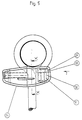
- FIG. 4a shows an inventive one Arrangement with a clamp body 24, a frame tube 10, a rope 25 and a clamping screw 26.
- the metal core 28 of the rope 25 is not included Plastic coated.
- the area where no sheathing is present corresponds in length to the thickness of a fork part 29, in which a fork space 30 is formed where the fork gap 30 is the diameter of the metal core 28 corresponds or dimensioned slightly larger than this is.
- the clamping body 24 has an opening 32 into which the Rope end 27 can be inserted with the block 31.
- clamping body 24 with one in FIG. 4 is not visible insertion recess into which the fork part 29 in the direction of arrow 2 with a press fit is.
- the clamping body 24 is attached to the frame tube 10 then by clamping the cable 25 by means of the clamping screw 26 analogous to those already described above Embodiments.
- the other parts of the clamp body shown in FIG. 5 24 correspond in their function to the embodiment according to FIG Fig. 1.
- Fig. 4a From Fig. 4a it can be seen that the rope end 34 with a lockable loop 35 can be connected.
- the lockable Loop 35 is thereby by means of a clamping and Formed closing body 36, which is a lock for locking of a locking block 37, the locking block 37 can be coupled to the rope end 34 by means of a screw connection is.
- This screw connection is in the closed state of the clamping and closing body 36 not accessible from the outside.
- the clamping and closing body 36 has a clamping device 38, which is spaced from the rope end 34 Clamp the area of area 25 in the clamping and closing body 36 can.
- the clamping is done by screwing in a grub screw 39 in the clamping device 38.
- the lockable loop is between the clamping device 38 and the locking block 37. You can in her Scope can be changed by the clamping device 38 released is, and the rope 25 through the through hole 40 of the Clamping and closing body 36 in the desired direction pushed to enlarge or reduce the size of the loop becomes.
- the lockable loop shown in Fig. 4a can also realized without the fastening device according to the invention will.
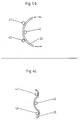
- 4b and 4c schematically show the operation of a compared to Fig. 4a alternative clamping.
- the clamping device 38 with grub screw 39 replaced by three bearing points 41, 42, 43 according to FIG. 4a, in cooperation with a curvature of the rope 25 a desired fixation of the rope 25 in a clamp or Closing body 36, which is equipped with the bearing points 41 to 43 is to cause.
- the three bearing points 41 to 43 are arranged so that the rope in the orientation shown in Fig. 4b due its intrinsic curvature easily by the between the Bearing points 41 to 43 trained gaps threaded and can be moved in its longitudinal direction.
- the circumference of the loop 35 (Fig. 4a) adjustable.
Landscapes
- Engineering & Computer Science (AREA)
- Mechanical Engineering (AREA)
- Clamps And Clips (AREA)
Applications Claiming Priority (2)
| Application Number | Priority Date | Filing Date | Title |
|---|---|---|---|
| DE19724912 | 1997-06-12 | ||
| DE19724912A DE19724912A1 (de) | 1997-06-12 | 1997-06-12 | Befestigungsvorrichtung |
Publications (3)
| Publication Number | Publication Date |
|---|---|
| EP0884236A2 true EP0884236A2 (fr) | 1998-12-16 |
| EP0884236A3 EP0884236A3 (fr) | 2000-07-19 |
| EP0884236B1 EP0884236B1 (fr) | 2003-04-16 |
Family
ID=7832308
Family Applications (1)
| Application Number | Title | Priority Date | Filing Date |
|---|---|---|---|
| EP98110040A Expired - Lifetime EP0884236B1 (fr) | 1997-06-12 | 1998-06-02 | Dispositif de montage |
Country Status (2)
| Country | Link |
|---|---|
| EP (1) | EP0884236B1 (fr) |
| DE (2) | DE19724912A1 (fr) |
Family Cites Families (14)
| Publication number | Priority date | Publication date | Assignee | Title |
|---|---|---|---|---|
| US1273922A (en) * | 1916-10-17 | 1918-07-30 | Alexander J Prattinger | Line-clutch. |
| DE1866536U (de) * | 1962-12-04 | 1963-01-31 | Apa Kg Bauder Otto | Vorrichtung zum bilden von seilschlingen, insbesondere an abschleppseilen fuer kraftfahrzeuge. |
| US4057982A (en) * | 1973-04-23 | 1977-11-15 | American Chain & Cable Company, Inc. | Theft-deterrent chain locking device |
| US3933015A (en) * | 1974-06-20 | 1976-01-20 | Balicki Stanley C | Armored cable-type lock assembly with special means for rendering it tamper-proof |
| US4028916A (en) * | 1976-04-13 | 1977-06-14 | Pender David R | Lock for bicycles and the like |
| GB2024307B (en) * | 1978-06-13 | 1982-03-31 | Neiman Sa | Restraining movement between two components |
| DE8325621U1 (de) * | 1983-09-07 | 1984-01-26 | Apa Gmbh & Co Otto Bauder, 7012 Fellbach | Verschlussvorrichtung fuer zweiraeder |
| DE8905160U1 (de) * | 1988-09-07 | 1989-10-12 | Aug. Winkhaus GmbH & Co KG, 4404 Telgte | Halterung für ein Langbügelschloß |
| DE8903908U1 (de) * | 1989-03-30 | 1989-06-22 | Basta Lasefabrik A/S, Korsor/Korsoer | Halter für Fahrradschloss |
| DE9012512U1 (de) * | 1990-08-31 | 1990-11-08 | Aug. Winkhaus GmbH & Co KG, 4404 Telgte | Spiralkabelschloßeinrichtung an oder zum Anbau an einem Zweiradrahmen |
| DE9115003U1 (de) * | 1991-12-03 | 1992-02-20 | Basta Lasefabrik A/S, Korsoer | Befestigungsbeschlag |
| DE4216595C1 (de) * | 1992-05-20 | 1993-12-09 | Andreas Gruethling | Diebstahlssicherung für bewegliche Gegenstände |
| DE9215866U1 (de) * | 1992-11-21 | 1993-01-21 | Ernhofer, Hans, 8859 Karlshuld | Anschließvorrichtung für Ski und Skistöcke |
| DE4304239C2 (de) * | 1993-02-12 | 1999-01-14 | Rixen & Kaul Gmbh | Befestigungsvorrichtung für Zubehör an Rohren oder Stangen |
-
1997
- 1997-06-12 DE DE19724912A patent/DE19724912A1/de not_active Withdrawn
-
1998
- 1998-06-02 DE DE59807927T patent/DE59807927D1/de not_active Expired - Fee Related
- 1998-06-02 EP EP98110040A patent/EP0884236B1/fr not_active Expired - Lifetime
Non-Patent Citations (1)
| Title |
|---|
| None |
Also Published As
| Publication number | Publication date |
|---|---|
| EP0884236A3 (fr) | 2000-07-19 |
| EP0884236B1 (fr) | 2003-04-16 |
| DE59807927D1 (de) | 2003-05-22 |
| DE19724912A1 (de) | 1998-12-17 |
Similar Documents
| Publication | Publication Date | Title |
|---|---|---|
| DE69302858T2 (de) | Seilklemme | |
| DE69415534T2 (de) | Wiederverwendbares siegel für einen stab | |
| DE10158005A1 (de) | Bügelzwinge | |
| LU84418A1 (de) | Kupplungselement | |
| DE3917392C2 (fr) | ||
| DE3020838C2 (fr) | ||
| EP0521490B1 (fr) | Arrangement de deux éléments de construction connectés télescopiquement l'un avec l'autre | |
| EP3404151B1 (fr) | Dispositif de fixation d'un objet sanitaire et utilisation d'un tel dispositif | |
| EP2329747B1 (fr) | Dispositif de serrage pour corde pour rideaux | |
| DE102005002782B4 (de) | Befestigungsvorrichtung zum Sichern eines Frachtcontainers mit einem Begrenzungsmechanismus | |
| EP0641908B1 (fr) | Serrure de câble, en particulier pour véhicules à deux roues | |
| DE19507715C1 (de) | Vorrichtung zur Befestigung eines Bauteiles an einem Träger | |
| EP0437211A1 (fr) | Point d'attache pour la fixation d'une pièce de montage à un baton de support | |
| EP0711894A2 (fr) | Crémone | |
| EP0884236B1 (fr) | Dispositif de montage | |
| DE102018101285A1 (de) | Eckverbinder | |
| EP1712458B1 (fr) | Unité réalisée avec un antivol de bicyclette | |
| DE4339042C1 (de) | Vorrichtung zur Befestigung eines Bauteils an einem Verbindungsstift | |
| DE4343877C1 (de) | Rohrschelle | |
| EP1116838A1 (fr) | Ferrure de protection pour porte | |
| EP0763640A2 (fr) | Dispositif de fermeture | |
| DE9212200U1 (de) | Handhabungswerkzeug | |
| DE19706560A1 (de) | Ringschloß zum Sichern von beweglichen Gegenständen, insbesondere Zweirädern oder dergleichen Fahrzeuge | |
| EP0340752B1 (fr) | Etrier à fente pour fixer un verrou de bicyclette au cadre | |
| DE19717188C1 (de) | Dreh- oder Schubstangenschloß |
Legal Events
| Date | Code | Title | Description |
|---|---|---|---|
| PUAI | Public reference made under article 153(3) epc to a published international application that has entered the european phase |
Free format text: ORIGINAL CODE: 0009012 |
|
| AK | Designated contracting states |
Kind code of ref document: A2 Designated state(s): DE GB NL |
|
| AX | Request for extension of the european patent |
Free format text: AL;LT;LV;MK;RO;SI |
|
| PUAL | Search report despatched |
Free format text: ORIGINAL CODE: 0009013 |
|
| AK | Designated contracting states |
Kind code of ref document: A3 Designated state(s): AT BE CH CY DE DK ES FI FR GB GR IE IT LI LU MC NL PT SE |
|
| AX | Request for extension of the european patent |
Free format text: AL;LT;LV;MK;RO;SI |
|
| 17P | Request for examination filed |
Effective date: 20001009 |
|
| AKX | Designation fees paid |
Free format text: DE GB NL |
|
| GRAH | Despatch of communication of intention to grant a patent |
Free format text: ORIGINAL CODE: EPIDOS IGRA |
|
| GRAH | Despatch of communication of intention to grant a patent |
Free format text: ORIGINAL CODE: EPIDOS IGRA |
|
| GRAA | (expected) grant |
Free format text: ORIGINAL CODE: 0009210 |
|
| AK | Designated contracting states |
Designated state(s): DE GB NL |
|
| REG | Reference to a national code |
Ref country code: GB Ref legal event code: FG4D Free format text: NOT ENGLISH |
|
| PGFP | Annual fee paid to national office [announced via postgrant information from national office to epo] |
Ref country code: GB Payment date: 20030512 Year of fee payment: 6 |
|
| REF | Corresponds to: |
Ref document number: 59807927 Country of ref document: DE Date of ref document: 20030522 Kind code of ref document: P |
|
| PGFP | Annual fee paid to national office [announced via postgrant information from national office to epo] |
Ref country code: NL Payment date: 20030617 Year of fee payment: 6 |
|
| GBT | Gb: translation of ep patent filed (gb section 77(6)(a)/1977) | ||
| PGFP | Annual fee paid to national office [announced via postgrant information from national office to epo] |
Ref country code: DE Payment date: 20030716 Year of fee payment: 6 |
|
| PLBE | No opposition filed within time limit |
Free format text: ORIGINAL CODE: 0009261 |
|
| STAA | Information on the status of an ep patent application or granted ep patent |
Free format text: STATUS: NO OPPOSITION FILED WITHIN TIME LIMIT |
|
| 26N | No opposition filed |
Effective date: 20040119 |
|
| PG25 | Lapsed in a contracting state [announced via postgrant information from national office to epo] |
Ref country code: GB Free format text: LAPSE BECAUSE OF NON-PAYMENT OF DUE FEES Effective date: 20040602 |
|
| PG25 | Lapsed in a contracting state [announced via postgrant information from national office to epo] |
Ref country code: NL Free format text: LAPSE BECAUSE OF NON-PAYMENT OF DUE FEES Effective date: 20050101 Ref country code: DE Free format text: LAPSE BECAUSE OF NON-PAYMENT OF DUE FEES Effective date: 20050101 |
|
| GBPC | Gb: european patent ceased through non-payment of renewal fee | ||
| NLV4 | Nl: lapsed or anulled due to non-payment of the annual fee |
Effective date: 20050101 |