EP0884237A1 - Dynamo pour bicyclette - Google Patents
Dynamo pour bicyclette Download PDFInfo
- Publication number
- EP0884237A1 EP0884237A1 EP97109562A EP97109562A EP0884237A1 EP 0884237 A1 EP0884237 A1 EP 0884237A1 EP 97109562 A EP97109562 A EP 97109562A EP 97109562 A EP97109562 A EP 97109562A EP 0884237 A1 EP0884237 A1 EP 0884237A1
- Authority
- EP
- European Patent Office
- Prior art keywords
- coil
- cylindrical
- stator
- induction coil
- rotor
- Prior art date
- Legal status (The legal status is an assumption and is not a legal conclusion. Google has not performed a legal analysis and makes no representation as to the accuracy of the status listed.)
- Withdrawn
Links
- 230000006698 induction Effects 0.000 claims abstract description 58
- 239000010410 layer Substances 0.000 description 10
- 239000003990 capacitor Substances 0.000 description 5
- 239000004020 conductor Substances 0.000 description 5
- 238000010276 construction Methods 0.000 description 3
- 230000000694 effects Effects 0.000 description 3
- 230000004907 flux Effects 0.000 description 3
- 238000005520 cutting process Methods 0.000 description 2
- 230000005611 electricity Effects 0.000 description 2
- 238000005530 etching Methods 0.000 description 2
- 239000000696 magnetic material Substances 0.000 description 2
- 238000004519 manufacturing process Methods 0.000 description 2
- 238000004804 winding Methods 0.000 description 2
- RYGMFSIKBFXOCR-UHFFFAOYSA-N Copper Chemical compound [Cu] RYGMFSIKBFXOCR-UHFFFAOYSA-N 0.000 description 1
- 229910052802 copper Inorganic materials 0.000 description 1
- 239000010949 copper Substances 0.000 description 1
- 238000009826 distribution Methods 0.000 description 1
- 230000005674 electromagnetic induction Effects 0.000 description 1
- 238000012986 modification Methods 0.000 description 1
- 230000004048 modification Effects 0.000 description 1
- 239000002356 single layer Substances 0.000 description 1
Images




Classifications
-
- H—ELECTRICITY
- H02—GENERATION; CONVERSION OR DISTRIBUTION OF ELECTRIC POWER
- H02K—DYNAMO-ELECTRIC MACHINES
- H02K3/00—Details of windings
- H02K3/04—Windings characterised by the conductor shape, form or construction, e.g. with bar conductors
- H02K3/26—Windings characterised by the conductor shape, form or construction, e.g. with bar conductors consisting of printed conductors
-
- B—PERFORMING OPERATIONS; TRANSPORTING
- B62—LAND VEHICLES FOR TRAVELLING OTHERWISE THAN ON RAILS
- B62J—CYCLE SADDLES OR SEATS; AUXILIARY DEVICES OR ACCESSORIES SPECIALLY ADAPTED TO CYCLES AND NOT OTHERWISE PROVIDED FOR, e.g. ARTICLE CARRIERS OR CYCLE PROTECTORS
- B62J6/00—Arrangement of optical signalling or lighting devices on cycles; Mounting or supporting thereof; Circuits therefor
- B62J6/06—Arrangement of lighting dynamos or drives therefor
- B62J6/12—Dynamos arranged in the wheel hub
-
- H—ELECTRICITY
- H02—GENERATION; CONVERSION OR DISTRIBUTION OF ELECTRIC POWER
- H02K—DYNAMO-ELECTRIC MACHINES
- H02K21/00—Synchronous motors having permanent magnets; Synchronous generators having permanent magnets
- H02K21/12—Synchronous motors having permanent magnets; Synchronous generators having permanent magnets with stationary armatures and rotating magnets
- H02K21/14—Synchronous motors having permanent magnets; Synchronous generators having permanent magnets with stationary armatures and rotating magnets with magnets rotating within the armatures
-
- H—ELECTRICITY
- H02—GENERATION; CONVERSION OR DISTRIBUTION OF ELECTRIC POWER
- H02K—DYNAMO-ELECTRIC MACHINES
- H02K21/00—Synchronous motors having permanent magnets; Synchronous generators having permanent magnets
- H02K21/12—Synchronous motors having permanent magnets; Synchronous generators having permanent magnets with stationary armatures and rotating magnets
- H02K21/24—Synchronous motors having permanent magnets; Synchronous generators having permanent magnets with stationary armatures and rotating magnets with magnets axially facing the armatures, e.g. hub-type cycle dynamos
Definitions
- This invention relates to a generator, and more particularly, to a generator included in a bicycle having relatively rotatable members.
- a generator (dynamo) installed in a bicycle includes a stator fixed to the frame of the bicycle, and a rotor which can be driven by frictional force produced by a bicycle wheel so as to rotate relative to the stator.
- a stator fixed to the frame of the bicycle
- a rotor which can be driven by frictional force produced by a bicycle wheel so as to rotate relative to the stator.
- electricity generation is carried out to generate a voltage of alternating sine wave. Since the air gap between the tooth and the rotor and the air gap between the slot and the rotor are greatly different from each other, the magnetic property of the stator changes from place to place, which is the so-called "slot effect".
- the object of this invention is to provide a bicycle generator which, when installed on a bicycle, will not increase the rider's load. Besides, the efficiency of the bicycle generator can be improved in comparison with a prior bicycle generator.
- a generator converts mechanical energy into electrical energy basing on the electromagnetic induction principle---namely, an electromotive force will be induced in a conductor which moves relative to a magnetic field.
- a generator comprises the following primary elements:
- magnitude of the induced emf generated by a generator is proportional to the magnetic field density, the number of turns of the coil(s), and the speed of relative motion of the coil(s) or the conductor.
- this invention provides a bicycle generator in which the front wheel of a bicycle is used as the required mechanical energy source, a magnetic rotor is attached to the front wheel for establishing the magnetic field, and a coil stator is fixed to the frame of the bicycle as the coil(s) for cutting the magnetic field so as to produce an induced electromotive force (emf).
- emf induced electromotive force
- a bicycle generator comprises: at least one layer of coil stator, including a planar support, and at least one turn of periodical wave-shaped induction coil which is formed by a plurality of series-connected wave-shaped segments and which is attached to and extends circumferentially on the planar support; and a magnetic rotor substantially parallel to the coil stator with a proper air gap being kept between the rotor and the stator, the rotor being rotatable relative to the stator and having a periphery along which is provided with a ring-shaped permanent magnet having multiple magnetic pole pairs of which the number is identical to the number of the wave-shaped segments.
- a bicycle generator comprises: at least one layer of coil stator, including a cylindrical support, and at least one turn of periodical wave-shaped induction coil which is formed by a plurality of series-connected wave-shaped segments and which is attached to and extends circumferentially on the cylindrical support; and a cylindrical magnetic rotor rotatable relative to the coil stator, including a cylindrical rotor surface which is opposite to the induction coil of the coil stator, and is substantially coaxial with and radially spaced, by a proper radial gap, from the cylindrical support of the coil stator, and a permanent magnet having multiple magnetic pole pairs which are circumferentially arranged on the cylindrical rotor surface and of which the number is identical to the number of the wave-shaped segments.
- a bicycle generator comprises a coil stator including a planar support, and an induction coil portion formed by a plurality of series-connected coil units which are evenly spaced along the circumference of the planar support; and a magnetic rotor rotatable relative to and substantially parallel to the coil stator, and including a permanent magnet having a plurality of magnetic pole pairs formed on the circumference thereof.
- the number of the coil units in the induction coil portion is equal to the number of the magnetic pole pairs in the magnetic rotor, and the coil units is winded into trapezoid or sector shape, and the span angle of each of the magnetic pole in the magnetic rotor is substantially equal to the span angle of each of the coil units in the coil stator.
- a bicycle generator comprises a cylindrical coil stator including a cylindrical support having a first cylindrical surface, and a cylindrical induction coil portion formed by a plurality of series-connected coil units which are evenly spaced on the first cylindrical surface of the cylindrical support in the circumferential direction; and a cylindrical magnetic rotor which is substantially coaxial with and radially spaced from the cylindrical coil stator with a constant radial gap therebetween, and rotatable relative to the cylindrical coil stator, and which includes a second cylindrical surface and a permanent magnet having a plurality of magnetic pole pairs formed on the second cylindrical surface facing the cylindrical induction coil portion.
- the number of the coil units of the cylindrical induction coil portion is equal to the number of the magnetic pole pairs of the cylindrical magnetic rotor.
- the coil units is winded into rectangular shape, and the span angle of each of the magnetic poles of the cylindrical magnetic rotor is substantially equal to the span angle of each of the coil units in the cylindrical coil stator.
- Figs. 1 and 2 are, respectively, the end view and front view of a generator according to the first embodiment of this invention, which is installed in a bicycle having relative rotatable members.
- the front wheel of a common bicycle is constituted by a front axle 2 fixed to the lower end of the front fork 1 of the bicycle frame 0, and a revolving assembly rotatably supported by the front axle 2.
- the revolving assembly includes a hub 3 and a tire 4 etc.
- This bicycle generator mainly includes a magnetic rotor 10 attached to the hub 3, a coil stator 20 fixed to the front axle 2, and a pair of lead wires 30 connected between the coil stator 20 and an outer load such as a bicycle lamp (see Figs. 3A, 4A and 10) for supplying electrical energy to the latter.
- Fig. 3A shows the construction of a simplest type of coil stator 20 in the bicycle generator according to the first embodiment of this invention.
- This coil stator 20 includes a disc-shaped support 21 made of soft magnetic materials and a coil 22 made of copper or other conductive materials which is formed on the support 21 by, for example, etching.
- This coil 22 consists of a single turn formed by a plurality of series-connected segments 23, each having a shape of rectangular pulse wave. The two ends of this coil 22 are connected to an outer load 40 through a pair of lead wires 30.
- Fig. 3B shows that this coil stator 20 can be constituted by only one layer.
- Fig. 4A shows the construction of another type of coil stator 20 in the generator of this invention. Slightly different from the above-described simplest type of coil stator including a single turn of induction coil (see Fig. 3A), this coil stator 20 has a coil 22 including two turns 22A and 22B of induction coils (Figs. 4A and 4B) which are formed on the same support 21, electrically isolated, and overlapped in radial direction.
- the tail end of the outer turn 22A is connected to the head end of the inner turn 22B so as to make the flowing directions of current in the inner and outer turns 22A, 22B consistent with each other.
- the head end of the outer turn 22A and the tail end of the inner turn 22B are connected to the lead wires 30, respectively.
- Fig. 4B shows a segment 23 of the coil 22.
- Fig. 4C shows the construction of yet another type of coil stator 20 in the bicycle generator of this invention.
- this coil stator 20 includes two superimposed and isolated layers 20A, 20B on which are arranged induction coils connected to each other only at their ends.
- the magnetic rotor 10 includes a disk-shaped frame 11, and a permanent magnet having multiple magnetic poles N, S, N, S, --- 12 which is attached onto the circumference of the frame 11.
- the number of the magnetic pole N or S in the magnetic rotor 10 is equal to the number of the segments 23 in the coil 22.
- the permanent magnet and the frame 11 may be integrally formed ( see Fig. 5C).
- the magnetic rotor 10 when installed on a bicycle, the magnetic rotor 10 is substantially parallel to the coil stator 20 with a proper air gap being kept between the rotor 10 and the stator 20. The rotor 10 can be rotated relative to the stator 20 in the direction of arrow C.
- the magnetic rotor 10 Since the magnetic rotor 10 has a rather small magnetic pole span angle ⁇ , namely the width of each magnetic pole 12 is rather small, the angular distributi0on of the magnetic flux density B along the circumference of the magnetic rotor 10 is near the shape of a rectangular pulse wave (see Fig. 6).
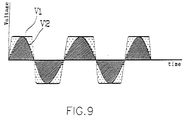
- the magnetic pole span angle ⁇ of the magnetic rotor 10 is made to be substantially identical to the span angle ⁇ of each segment in the induction coils 22. Consequently, in the case when the magnetic rotor 10 and the coil stator 20 are installed on the hub 3 and the axle 2 respectively (see Fig. 1), and the magnetic rotor 10 revolves together with the hub 3, a nearly rectangular pulse wave-shaped voltage V1(see Fig. 7) can be induced in the induction coils 22 of the coil stator 20 due to the fact that the coils 22 cut the magnetic field produced by the magnetic rotor 10.
- the induced voltage V1 having a nearly rectangular pulse wave shape (see Fig. 7), produced by the generator of this invention is compared with the voltage V2, having a sine wave shape ( see Fig. 8), produced by a conventional generator.
- the former voltage V1 has a valid voltage wave area larger than that of the latter voltage V2.
- the generator of this invention has a better efficiency in electricity generation.
- both the rotor and the stator are of planar shapes and are parallel to each other, the air gap between them keeps constant. Consequently, no "slot effect" problem or reluctance torque problem occurs in a generator of this invention.
- the rider's load can be reduced and the efficiency of generator can be greatly improved in comparison with a conventional bicycle generator as described above.
- a rectifier 41 and a capacitor 42 are further provided intermediate the pair of lead wires 30 connected between the induction coils 22 and an outer load 40 (see Fig. 10) so as to stabilize the current supplied by the generator and to avoid interruption of current supply when the bicycle stops.
- the generator according to this embodiment includes a cylindrical magnetic rotor 50 and at least one layer of coil stator 60.
- Each layer of the coil stator 60 includes a cylindrical support 61 made of soft magnetic materials, and at least one turn of periodical wave-shaped induction coil 62 which is attached to and extends circumferentially on the surface of the cylindrical support 61.
- the two ends of the induction coil 62 are connected to an outer load (not shown) through a pair of lead wires 30.
- the coil stator 60 shown in Fig. 11 includes only a single layer of periodical wave-shaped induction coil 62, this coil stator 60 may alternatively include a plurality of induction coils 62 which are arranged on multiple coaxial cylindrical layers and are connected together. Besides, the at least one turn of induction coil 62 of the coil stator 60 may include a plurality of different turns of induction coil 62 which are arranged on the same layer of coil stator 60 and are connected together.
- the cylindrical magnetic rotor 50 is substantially coaxial with and radially spaced, by a proper radial gap, from the cylindrical support 61 of the coil stator 60, and may rotate relative to the coil stator 60 in the direction of arrow ⁇ .
- the magnetic rotor 50 has a cylindrical rotor surface, opposite to the induction coil 62 of the coil stator 60, on which is provided a permanent magnet having a plurality of circumferentially arranged magnetic poles N, S, N, S, --- 51.
- each turn of periodical wave-shaped induction coil includes a plurality of rectangular pulse-shaped segments connected in series, and each magnetic pole 51 in the magnetic rotor 50 has a magnetic pole span angle ⁇ substantially identical to the span angle ⁇ of each segment in the induction coil 62.
- the magnetic rotor 50 may comprise a separate frame (not shown) onto which is attached the permanent magnet.
- a rectifier and a capacitor may preferably be provided intermediate the pair of lead wires 30 connected between the induction coil 62 and an outer load so as to stabilize the current supply.
- bicycle generator of the third embodiment also includes a magnetic rotor 10, which is exactly the same as that used in the first embodiment and shown in Figs. 5A through 5C, and a disk-shaped coil stator 20.
- the coil stator 20 includes a disk-shaped planar support 21, an induction coil portion 22 formed by a plurality of series-connected coil units 23 which are evenly spaced along the circumference of the planar support 21, and a pair of lead wires 30 which connect the terminals of the induction coil portion 22 and the external load 40. Adjacent coil units 23 are connected to each other by lines 24 between them.
- FIG. 12B is an enlarged view showing the structure of a coil unit 23 included in the coil stator 20 illustrated in Fig. 12A.
- a coil unit 23 is composed of several coil loops, each loop being winded into a trapezoid or sector shape.
- the number of coil units 23 of the induction coil portion 22 is the same as the number of magnetic pole pairs 12 of the magnetic rotor 10 (see Fig. 5A).
- each coil unit 23 is illustrated to include three loops in Fig. 12B, the loop number of a coil unit 23 certainly need not be limited to three.
- the bicycle generator according to the third embodiment is similar to that according to the first embodiment in the function thereof, the ways of forming the coil stators and particularly the induction coil portions are completely different.
- all the coil units 23 constituting the induction coil portion 22 may be formed one by one by automatic winding operation.
- the whole coil stator 20 may be produced by an automatic manufacturing process at high speed.
- a rectifier and a capacitor may preferably be provided intermediate the pair of lead wires 30 connected between the circular induction coil 22 and an outer load 40 so as to stabilize the current supply.
- bicycle generator of the fourth embodiment also includes a cylindrical magnetic rotor 50, which is exactly the same as that used in the second embodiment and shown in Fig. 11, a cylindrical coil stator 60, and a pair of lead wires 30 which connect the terminals of the cylindrical induction coil portion 62 and an external load (not shown).
- the cylindrical coil stator 60 includes a cylindrical support 61 having a first cylindrical surface, and a cylindrical induction coil portion 63 formed by a plurality of series-connected coil units 62 (only five coil units 62 are shown in Fig. 10) which are evenly spaced on the first cylindrical surface of the cylindrical support 61 in the circumferential direction. Though each coil unit 62 is illustrated to include three substantially rectangular loops in Fig. 13, the loop number of a coil unit 62 certainly need not be limited to three.
- all the coil units 62 constituting the induction coil portion 63 may be formed one by one by automatic winding operation.
- the whole coil stator 60 may be produced by an automatic manufacturing process at high speed.
- a rectifier and a capacitor may preferably be provided intermediate the pair of lead wires 30 connected between the induction coil portion 63 and an outer load so as to stabilize the current supply.
Landscapes
- Engineering & Computer Science (AREA)
- Power Engineering (AREA)
- Mechanical Engineering (AREA)
- Permanent Magnet Type Synchronous Machine (AREA)
- Windings For Motors And Generators (AREA)
- Synchronous Machinery (AREA)
Priority Applications (2)
| Application Number | Priority Date | Filing Date | Title |
|---|---|---|---|
| US08/872,174 US5874792A (en) | 1997-06-10 | 1997-06-10 | Bicycle generator |
| EP97109562A EP0884237A1 (fr) | 1997-06-10 | 1997-06-11 | Dynamo pour bicyclette |
Applications Claiming Priority (2)
| Application Number | Priority Date | Filing Date | Title |
|---|---|---|---|
| US08/872,174 US5874792A (en) | 1997-06-10 | 1997-06-10 | Bicycle generator |
| EP97109562A EP0884237A1 (fr) | 1997-06-10 | 1997-06-11 | Dynamo pour bicyclette |
Publications (1)
| Publication Number | Publication Date |
|---|---|
| EP0884237A1 true EP0884237A1 (fr) | 1998-12-16 |
Family
ID=26145531
Family Applications (1)
| Application Number | Title | Priority Date | Filing Date |
|---|---|---|---|
| EP97109562A Withdrawn EP0884237A1 (fr) | 1997-06-10 | 1997-06-11 | Dynamo pour bicyclette |
Country Status (2)
| Country | Link |
|---|---|
| US (1) | US5874792A (fr) |
| EP (1) | EP0884237A1 (fr) |
Cited By (4)
| Publication number | Priority date | Publication date | Assignee | Title |
|---|---|---|---|---|
| WO2003105314A1 (fr) * | 2002-06-01 | 2003-12-18 | Reelight Aps | Generateur pour bicyclette |
| WO2013148245A1 (fr) * | 2012-03-30 | 2013-10-03 | Kollmorgen Corporation | Orientation de flux, définition de portée, attribut sur la stratification de rotor de moteur/générateur électrique refroidi par air |
| WO2016087484A1 (fr) * | 2014-12-03 | 2016-06-09 | BABELUK, Michael | Unité d'entraînement pour équiper ou rééquiper un deux roues |
| WO2016173033A1 (fr) * | 2015-04-30 | 2016-11-03 | 上海津元节能科技有限公司 | Système à autonomie prolongée par récupération d'énergie dynamique sur l'ensemble du processus et procédés à autonomie prolongée pour bicyclettes électriques pures |
Families Citing this family (24)
| Publication number | Priority date | Publication date | Assignee | Title |
|---|---|---|---|---|
| IT1297070B1 (it) * | 1997-11-21 | 1999-08-03 | Micronasa Di Patarchi Alberto | Macchina dinamoelettrica rotante a induzione elettromagnetica come agente in motori elettrici lineari. |
| DE29921874U1 (de) | 1999-12-13 | 2000-04-13 | Müller, Michael, 51377 Leverkusen | Elektromagnetische Maschine für ein Fahrzeug, insbesondere ein Fahrrad |
| US6502842B2 (en) * | 2001-01-30 | 2003-01-07 | Frank Ko | Bicycle power generating arrangement |
| GB2379804B (en) * | 2001-09-15 | 2003-08-06 | Far Great Plastics Ind Co Ltd | Vehicle electrical generator |
| US6703716B2 (en) * | 2001-10-17 | 2004-03-09 | Meng-Yu Liu | Permanent magnet generator for bicycle light operation |
| JP3785095B2 (ja) * | 2002-01-16 | 2006-06-14 | シロウマサイエンス株式会社 | 足踏式発電健康装置 |
| US6802385B2 (en) * | 2002-05-16 | 2004-10-12 | Wavecrest Laboratories, Llc | Electrically powered vehicles having motor and power supply contained within wheels |
| GB2389465A (en) * | 2002-06-07 | 2003-12-10 | Far Great Plastics Ind Co Ltd | Geared generator for skateboard |
| US20040026883A1 (en) * | 2002-08-09 | 2004-02-12 | Ting-Hsing Chen | Generator structure for a tri-wheel scooter |
| US7382233B2 (en) * | 2004-05-08 | 2008-06-03 | Scott Steinetz | Sampling playback doorbell system |
| KR20060085382A (ko) * | 2005-01-24 | 2006-07-27 | 주식회사 현대오토넷 | 타이어 공기압 경보시스템의 정자계를 이용한 전원장치 |
| CN101208853A (zh) * | 2005-03-23 | 2008-06-25 | 波峰实验室责任有限公司 | 电机及制造方法 |
| US20070002575A1 (en) * | 2005-06-30 | 2007-01-04 | Han-Chung Chiang | Self-sufficient energy lighting device |
| US7608933B2 (en) * | 2005-10-31 | 2009-10-27 | Xiao (Charles) Yang | Method and structure for kinetic energy based generator for portable electronic devices |
| US20070188037A1 (en) * | 2006-02-15 | 2007-08-16 | Lau Shing L | An add-on kit comprising a ring of magnets installed onto a bicycle/car wheel; electromagnets installed onto a bike fork or car suspension which then provide assisted rotation. |
| US20090174295A1 (en) * | 2008-01-08 | 2009-07-09 | Ming-Chuan Lin | Generating apparatus using magnetic induction to generate electrical energy to provide illuminating function |
| JP5474409B2 (ja) * | 2009-06-01 | 2014-04-16 | 株式会社シマノ | 発電ハブ |
| US9527540B2 (en) * | 2011-07-15 | 2016-12-27 | Revolights, Inc. | Bicycle lighting systems and methods |
| US8337060B1 (en) * | 2011-07-15 | 2012-12-25 | John Kent Frankovich | Bicycle lighting systems and methods |
| US9227559B2 (en) | 2012-12-31 | 2016-01-05 | Revolights, Inc. | Vehicle lighting control system and method |
| DE202013102672U1 (de) * | 2013-06-20 | 2014-09-23 | Hightec Edv-Systeme Gmbh | Kabelanschluss für eine Motorbaueinheit eines elektrischen Fahrradhilfsantriebs |
| US10473680B2 (en) * | 2016-10-24 | 2019-11-12 | Noa Technologies, Inc. | Wheel unit with a location sensor |
| US10393365B2 (en) | 2017-04-05 | 2019-08-27 | Revolights, Inc. | Wheelchair lighting systems and methods |
| US10894573B2 (en) * | 2017-09-28 | 2021-01-19 | Pengjie Hu | Electric power-assist drive assembly for a spoked-wheeled vehicle |
Citations (4)
| Publication number | Priority date | Publication date | Assignee | Title |
|---|---|---|---|---|
| US4695419A (en) * | 1983-09-28 | 1987-09-22 | Tokuzo Inariba | Manufacture of a miniature electric motor |
| US4883981A (en) * | 1986-06-04 | 1989-11-28 | Gerfast Sten R | Dynamoelectric machine having ironless stator coil |
| DE9110860U1 (de) * | 1991-09-02 | 1991-10-17 | Scheffler, Jörg, O-8010 Dresden | Fahrradlichtmaschine |
| DE29613756U1 (de) * | 1996-08-09 | 1996-10-10 | Industrial Technology Research Institute, Chutung, Hsinchu | Generator |
Family Cites Families (4)
| Publication number | Priority date | Publication date | Assignee | Title |
|---|---|---|---|---|
| US3884317A (en) * | 1974-03-05 | 1975-05-20 | Augustus B Kinzel | Electrically powered cycle |
| US4559462A (en) * | 1984-05-30 | 1985-12-17 | Hernandez Badillo Wilfredo | Dynamo-electric cycle axle |
| WO1987005575A1 (fr) * | 1986-03-13 | 1987-09-24 | Frank Bauwens | Dispositif d'eclairage pour vehicule |
| CH681840A5 (fr) * | 1991-08-20 | 1993-05-28 | Ver Drahtwerke Ag |
-
1997
- 1997-06-10 US US08/872,174 patent/US5874792A/en not_active Expired - Lifetime
- 1997-06-11 EP EP97109562A patent/EP0884237A1/fr not_active Withdrawn
Patent Citations (4)
| Publication number | Priority date | Publication date | Assignee | Title |
|---|---|---|---|---|
| US4695419A (en) * | 1983-09-28 | 1987-09-22 | Tokuzo Inariba | Manufacture of a miniature electric motor |
| US4883981A (en) * | 1986-06-04 | 1989-11-28 | Gerfast Sten R | Dynamoelectric machine having ironless stator coil |
| DE9110860U1 (de) * | 1991-09-02 | 1991-10-17 | Scheffler, Jörg, O-8010 Dresden | Fahrradlichtmaschine |
| DE29613756U1 (de) * | 1996-08-09 | 1996-10-10 | Industrial Technology Research Institute, Chutung, Hsinchu | Generator |
Cited By (5)
| Publication number | Priority date | Publication date | Assignee | Title |
|---|---|---|---|---|
| WO2003105314A1 (fr) * | 2002-06-01 | 2003-12-18 | Reelight Aps | Generateur pour bicyclette |
| WO2013148245A1 (fr) * | 2012-03-30 | 2013-10-03 | Kollmorgen Corporation | Orientation de flux, définition de portée, attribut sur la stratification de rotor de moteur/générateur électrique refroidi par air |
| WO2016087484A1 (fr) * | 2014-12-03 | 2016-06-09 | BABELUK, Michael | Unité d'entraînement pour équiper ou rééquiper un deux roues |
| US10507887B2 (en) | 2014-12-03 | 2019-12-17 | Daniel Kerschgens | Drive unit for fitting or retrofitting a bicycle |
| WO2016173033A1 (fr) * | 2015-04-30 | 2016-11-03 | 上海津元节能科技有限公司 | Système à autonomie prolongée par récupération d'énergie dynamique sur l'ensemble du processus et procédés à autonomie prolongée pour bicyclettes électriques pures |
Also Published As
| Publication number | Publication date |
|---|---|
| US5874792A (en) | 1999-02-23 |
Similar Documents
| Publication | Publication Date | Title |
|---|---|---|
| EP0884237A1 (fr) | Dynamo pour bicyclette | |
| US7554241B2 (en) | Three-gapped motor with outer rotor and stationary shaft | |
| US5866965A (en) | Variable reluctance motor having foil wire wound coils | |
| US7902710B2 (en) | Electric machine | |
| EP0196086B1 (fr) | Assemblage d'enroulement pour machine électrique en rotation | |
| US6995494B2 (en) | Axial gap brushless DC motor | |
| US6756719B1 (en) | Electrical generator with separated coil and set of magnets | |
| US20070024144A1 (en) | Disk alternator | |
| US6940200B2 (en) | Electric drive | |
| US20200227991A1 (en) | Electrical machine | |
| JPH0150186B2 (fr) | ||
| JPH10504699A (ja) | 永久磁石間に軸方向の空隙を有する電気機器 | |
| JPH0556612A (ja) | デイスク型回転電機及びその固定子部分 | |
| JP2003506005A (ja) | 電気駆動装置(選択可能な形態) | |
| JP2005522972A5 (fr) | ||
| JP2005522972A (ja) | 軸方向界磁式同期電気機械 | |
| US4782259A (en) | Frequency generator and motor with the same | |
| US4605873A (en) | Electromechanical machine | |
| US4859890A (en) | Flat windings and coil forms | |
| US4691746A (en) | Flat windings, coil forms, and winding method | |
| US20020067102A1 (en) | Machine with cup-shaped armature and air gap | |
| WO2015193562A1 (fr) | Moteur synchrone électromagnétique à flux magnétiques combinés axial et radial | |
| US20230274880A1 (en) | Method of manufacturing permanent magnet of rotor for axial flux electric machine yielding permanent magnet with low loss and low cost | |
| US20070228859A1 (en) | Gapped motor with outer rotor and stationary shaft | |
| JP2006025486A (ja) | 回転電機 |
Legal Events
| Date | Code | Title | Description |
|---|---|---|---|
| PUAI | Public reference made under article 153(3) epc to a published international application that has entered the european phase |
Free format text: ORIGINAL CODE: 0009012 |
|
| AK | Designated contracting states |
Kind code of ref document: A1 Designated state(s): AT CH DK FI FR LI NL SE |
|
| AKX | Designation fees paid |
Free format text: AT CH DK FI FR LI NL SE |
|
| STAA | Information on the status of an ep patent application or granted ep patent |
Free format text: STATUS: THE APPLICATION IS DEEMED TO BE WITHDRAWN |
|
| 18D | Application deemed to be withdrawn |
Effective date: 19990617 |