EP0884402A1 - Méthode de fabrication d'une tôle pour formation de boítiers de pile et tôle obtenu par cette méthode - Google Patents
Méthode de fabrication d'une tôle pour formation de boítiers de pile et tôle obtenu par cette méthode Download PDFInfo
- Publication number
- EP0884402A1 EP0884402A1 EP98110727A EP98110727A EP0884402A1 EP 0884402 A1 EP0884402 A1 EP 0884402A1 EP 98110727 A EP98110727 A EP 98110727A EP 98110727 A EP98110727 A EP 98110727A EP 0884402 A1 EP0884402 A1 EP 0884402A1
- Authority
- EP
- European Patent Office
- Prior art keywords
- plate
- battery
- steel plate
- metal
- hot
- Prior art date
- Legal status (The legal status is an assumption and is not a legal conclusion. Google has not performed a legal analysis and makes no representation as to the accuracy of the status listed.)
- Ceased
Links
Images


Classifications
-
- C—CHEMISTRY; METALLURGY
- C23—COATING METALLIC MATERIAL; COATING MATERIAL WITH METALLIC MATERIAL; CHEMICAL SURFACE TREATMENT; DIFFUSION TREATMENT OF METALLIC MATERIAL; COATING BY VACUUM EVAPORATION, BY SPUTTERING, BY ION IMPLANTATION OR BY CHEMICAL VAPOUR DEPOSITION, IN GENERAL; INHIBITING CORROSION OF METALLIC MATERIAL OR INCRUSTATION IN GENERAL
- C23C—COATING METALLIC MATERIAL; COATING MATERIAL WITH METALLIC MATERIAL; SURFACE TREATMENT OF METALLIC MATERIAL BY DIFFUSION INTO THE SURFACE, BY CHEMICAL CONVERSION OR SUBSTITUTION; COATING BY VACUUM EVAPORATION, BY SPUTTERING, BY ION IMPLANTATION OR BY CHEMICAL VAPOUR DEPOSITION, IN GENERAL
- C23C24/00—Coating starting from inorganic powder
- C23C24/08—Coating starting from inorganic powder by application of heat or pressure and heat
- C23C24/082—Coating starting from inorganic powder by application of heat or pressure and heat without intermediate formation of a liquid in the layer
- C23C24/085—Coating with metallic material, i.e. metals or metal alloys, optionally comprising hard particles, e.g. oxides, carbides or nitrides
-
- B—PERFORMING OPERATIONS; TRANSPORTING
- B32—LAYERED PRODUCTS
- B32B—LAYERED PRODUCTS, i.e. PRODUCTS BUILT-UP OF STRATA OF FLAT OR NON-FLAT, e.g. CELLULAR OR HONEYCOMB, FORM
- B32B15/00—Layered products comprising a layer of metal
- B32B15/01—Layered products comprising a layer of metal all layers being exclusively metallic
- B32B15/012—Layered products comprising a layer of metal all layers being exclusively metallic one layer being formed of an iron alloy or steel, another layer being formed of aluminium or an aluminium alloy
-
- B—PERFORMING OPERATIONS; TRANSPORTING
- B32—LAYERED PRODUCTS
- B32B—LAYERED PRODUCTS, i.e. PRODUCTS BUILT-UP OF STRATA OF FLAT OR NON-FLAT, e.g. CELLULAR OR HONEYCOMB, FORM
- B32B15/00—Layered products comprising a layer of metal
- B32B15/01—Layered products comprising a layer of metal all layers being exclusively metallic
- B32B15/013—Layered products comprising a layer of metal all layers being exclusively metallic one layer being formed of an iron alloy or steel, another layer being formed of a metal other than iron or aluminium
- B32B15/015—Layered products comprising a layer of metal all layers being exclusively metallic one layer being formed of an iron alloy or steel, another layer being formed of a metal other than iron or aluminium the said other metal being copper or nickel or an alloy thereof
-
- B—PERFORMING OPERATIONS; TRANSPORTING
- B32—LAYERED PRODUCTS
- B32B—LAYERED PRODUCTS, i.e. PRODUCTS BUILT-UP OF STRATA OF FLAT OR NON-FLAT, e.g. CELLULAR OR HONEYCOMB, FORM
- B32B15/00—Layered products comprising a layer of metal
- B32B15/01—Layered products comprising a layer of metal all layers being exclusively metallic
- B32B15/018—Layered products comprising a layer of metal all layers being exclusively metallic one layer being formed of a noble metal or a noble metal alloy
-
- C—CHEMISTRY; METALLURGY
- C23—COATING METALLIC MATERIAL; COATING MATERIAL WITH METALLIC MATERIAL; CHEMICAL SURFACE TREATMENT; DIFFUSION TREATMENT OF METALLIC MATERIAL; COATING BY VACUUM EVAPORATION, BY SPUTTERING, BY ION IMPLANTATION OR BY CHEMICAL VAPOUR DEPOSITION, IN GENERAL; INHIBITING CORROSION OF METALLIC MATERIAL OR INCRUSTATION IN GENERAL
- C23C—COATING METALLIC MATERIAL; COATING MATERIAL WITH METALLIC MATERIAL; SURFACE TREATMENT OF METALLIC MATERIAL BY DIFFUSION INTO THE SURFACE, BY CHEMICAL CONVERSION OR SUBSTITUTION; COATING BY VACUUM EVAPORATION, BY SPUTTERING, BY ION IMPLANTATION OR BY CHEMICAL VAPOUR DEPOSITION, IN GENERAL
- C23C24/00—Coating starting from inorganic powder
- C23C24/08—Coating starting from inorganic powder by application of heat or pressure and heat
-
- C—CHEMISTRY; METALLURGY
- C23—COATING METALLIC MATERIAL; COATING MATERIAL WITH METALLIC MATERIAL; CHEMICAL SURFACE TREATMENT; DIFFUSION TREATMENT OF METALLIC MATERIAL; COATING BY VACUUM EVAPORATION, BY SPUTTERING, BY ION IMPLANTATION OR BY CHEMICAL VAPOUR DEPOSITION, IN GENERAL; INHIBITING CORROSION OF METALLIC MATERIAL OR INCRUSTATION IN GENERAL
- C23C—COATING METALLIC MATERIAL; COATING MATERIAL WITH METALLIC MATERIAL; SURFACE TREATMENT OF METALLIC MATERIAL BY DIFFUSION INTO THE SURFACE, BY CHEMICAL CONVERSION OR SUBSTITUTION; COATING BY VACUUM EVAPORATION, BY SPUTTERING, BY ION IMPLANTATION OR BY CHEMICAL VAPOUR DEPOSITION, IN GENERAL
- C23C26/00—Coating not provided for in groups C23C2/00 - C23C24/00
-
- H—ELECTRICITY
- H01—ELECTRIC ELEMENTS
- H01M—PROCESSES OR MEANS, e.g. BATTERIES, FOR THE DIRECT CONVERSION OF CHEMICAL ENERGY INTO ELECTRICAL ENERGY
- H01M50/00—Constructional details or processes of manufacture of the non-active parts of electrochemical cells other than fuel cells, e.g. hybrid cells
- H01M50/10—Primary casings; Jackets or wrappings
- H01M50/116—Primary casings; Jackets or wrappings characterised by the material
- H01M50/117—Inorganic material
- H01M50/119—Metals
-
- H—ELECTRICITY
- H01—ELECTRIC ELEMENTS
- H01M—PROCESSES OR MEANS, e.g. BATTERIES, FOR THE DIRECT CONVERSION OF CHEMICAL ENERGY INTO ELECTRICAL ENERGY
- H01M50/00—Constructional details or processes of manufacture of the non-active parts of electrochemical cells other than fuel cells, e.g. hybrid cells
- H01M50/10—Primary casings; Jackets or wrappings
- H01M50/116—Primary casings; Jackets or wrappings characterised by the material
- H01M50/124—Primary casings; Jackets or wrappings characterised by the material having a layered structure
- H01M50/1243—Primary casings; Jackets or wrappings characterised by the material having a layered structure characterised by the internal coating on the casing
-
- H—ELECTRICITY
- H01—ELECTRIC ELEMENTS
- H01M—PROCESSES OR MEANS, e.g. BATTERIES, FOR THE DIRECT CONVERSION OF CHEMICAL ENERGY INTO ELECTRICAL ENERGY
- H01M50/00—Constructional details or processes of manufacture of the non-active parts of electrochemical cells other than fuel cells, e.g. hybrid cells
- H01M50/10—Primary casings; Jackets or wrappings
- H01M50/131—Primary casings; Jackets or wrappings characterised by physical properties, e.g. gas permeability, size or heat resistance
- H01M50/133—Thickness
-
- H—ELECTRICITY
- H01—ELECTRIC ELEMENTS
- H01M—PROCESSES OR MEANS, e.g. BATTERIES, FOR THE DIRECT CONVERSION OF CHEMICAL ENERGY INTO ELECTRICAL ENERGY
- H01M50/00—Constructional details or processes of manufacture of the non-active parts of electrochemical cells other than fuel cells, e.g. hybrid cells
- H01M50/10—Primary casings; Jackets or wrappings
- H01M50/131—Primary casings; Jackets or wrappings characterised by physical properties, e.g. gas permeability, size or heat resistance
- H01M50/134—Hardness
-
- H—ELECTRICITY
- H01—ELECTRIC ELEMENTS
- H01M—PROCESSES OR MEANS, e.g. BATTERIES, FOR THE DIRECT CONVERSION OF CHEMICAL ENERGY INTO ELECTRICAL ENERGY
- H01M50/00—Constructional details or processes of manufacture of the non-active parts of electrochemical cells other than fuel cells, e.g. hybrid cells
- H01M50/10—Primary casings; Jackets or wrappings
- H01M50/14—Primary casings; Jackets or wrappings for protecting against damage caused by external factors
- H01M50/145—Primary casings; Jackets or wrappings for protecting against damage caused by external factors for protecting against corrosion
-
- H—ELECTRICITY
- H01—ELECTRIC ELEMENTS
- H01M—PROCESSES OR MEANS, e.g. BATTERIES, FOR THE DIRECT CONVERSION OF CHEMICAL ENERGY INTO ELECTRICAL ENERGY
- H01M50/00—Constructional details or processes of manufacture of the non-active parts of electrochemical cells other than fuel cells, e.g. hybrid cells
- H01M50/50—Current conducting connections for cells or batteries
- H01M50/543—Terminals
- H01M50/545—Terminals formed by the casing of the cells
-
- Y—GENERAL TAGGING OF NEW TECHNOLOGICAL DEVELOPMENTS; GENERAL TAGGING OF CROSS-SECTIONAL TECHNOLOGIES SPANNING OVER SEVERAL SECTIONS OF THE IPC; TECHNICAL SUBJECTS COVERED BY FORMER USPC CROSS-REFERENCE ART COLLECTIONS [XRACs] AND DIGESTS
- Y02—TECHNOLOGIES OR APPLICATIONS FOR MITIGATION OR ADAPTATION AGAINST CLIMATE CHANGE
- Y02E—REDUCTION OF GREENHOUSE GAS [GHG] EMISSIONS, RELATED TO ENERGY GENERATION, TRANSMISSION OR DISTRIBUTION
- Y02E60/00—Enabling technologies; Technologies with a potential or indirect contribution to GHG emissions mitigation
- Y02E60/10—Energy storage using batteries
Definitions
- the present invention relates to a method of manufacturing a battery can-forming plate and the battery can-forming plate manufactured by the method.
- Batteries are used as a power source of various kinds of cordless equipments such as personal lap-top computers, cellular telephones, and the like which are widely used in recent years.
- the space occupied by the batteries is very large.
- battery cans are required to have high capacities.
- the outer shapes of the battery cans are specified by the international standard. In order to allow the battery cans to have high capacity, it is necessary to make the thickness thereof small.
- a battery can-forming plate is hitherto manufactured by hot-rolling casted slab, then by cold-rolling a resulting hot-rolled steel plate to a required thickness, and then, by plating the cold-rolled steel plate with nickel or other metals.
- the annealing after the plating is performed and the skin pass rolling are intended to form a diffusion layer between iron of the steel plate and the plated metal layer.
- the present invention has been made in view of the above-described problem. It is an object of the present invention to form a metal layer on a steel plate, for example, by plating in a short period of time so that a great deal of surface-treating operation can be accomplished in a short period of time and with high productivity.
- a method of manufacturing a battery can-forming plate comprising the steps of:
- the metal layer can be formed on the surface of the hot-rolled steel plate by spreading metal powder on or applying them in the form of paste to the surface of the steel plate, annealing and then rolling the plate. Because the surface area of the hot-rolled steel plate is smaller than that of a cold-roiled steel plate, the metal layer can be formed in a short period of time and thus the productivity can be enhanced.
- the length per unit weight in the cold-rolled steel plate is about 7.5 as great as that of the hot-rolled steel plate.
- the surface area of the hot-rolled steel plate is about 1/7.5 times as small as that of the cold-rolled steel plate. That is, the metal layer is formed on the surface of the hot-rolled steel plate at about 1/7.5 times as small as that of the cold-roiled steel plate.
- a method of manufacturing a battery can-forming plate comprising the steps of:
- the metal layer can be formed on the hot-rolled steel plate in a short period of time and with a high productivity, because the surface area of the hot-rolled steel plate is smaller than that of a cold-rolled steel plate.
- a method of manufacturing a battery can-forming plate comprising the steps of:
- the third method in the present invention is combination of the first method and the second method. That is, after the hot-rolled steel plate is plated, the metal layer consisting of metal powder is formed on the plated metal layer.
- the third method allows the thickness of the plated metal layer to be thin. Further, the metal layer can be easily formed of a metal which is different from a metal of the plated layer and a metal such as aluminum which is difficult to form the plated layer.
- annealing is performed again to form a diffusion layer between the hot-rolled steel plate and the metal layer or between the plated layer and the metal layer of metal powder, and then the cold-rolling is performed.
- the degree of the adhesion between the metal layer and the steel plate as well as the plated layer can be enhanced. Further, this method allows rolling to be accomplished at a high rolling percentage without the metal layer being separated from the steel plate in the cold-rolling which is performed subsequently to the formation of the diffusion layer. Therefore, the method allows the thickness of the steel plate to be small and allows the thickness of a battery can-forming plate to be small.
- a metal is plated to form plated metal layer, and then annealing is performed again.
- plating is performed, and then, annealing and skin pass rolling are performed. That is, after the metal layer consisting of metal powder is formed on the surface of the hot-rolled steel plate, the metal layer is plated or after the cold-rolling is performed, plating is performed. In this manner, it is possible to form a plated layer consisting of a kind of metal different from the kind of the metal forming the metal layer on the surface of the steel plate.
- Said metal powder is selected from Ni, Al, In, Ca, Ag, Ge, Co, Sn, Sr, Se, Pb, Ba, Bi, Be, B, Mn, P, Cr, Si, C, Cu, Fe, Zn, La, W, Ti, Mo, and Ga or an alloy thereof or mixture of two or more kind of the metal powders.
- Ni or the following alloys can be preferably used: Ni or an alloy of Ni-Mn, Ni-In, Ni-Ag, Ni-Ge, Ni-Co, Ni-Sn, Ni-Se, Ni-B, Ni-P, Ni-Si, Ni-Fe, Ni-Zn, Ni-La, Ni-W, Ni-Ti, Ni-Mo, Ni-Ga, Co-Mo, Fe-W, and Ag-Sn.
- the rolling rate in the cold-rolling which is subsequently performed is preferably 80% - 90%. That is, the hot-rolled steel plate having a thickness of 1mm - 6mm is formed as a cold-rolled steel plate having a thickness of 0.1mm - 0.8mm.
- the rolling rate which is carried out to enhance the adhesion between iron of the steel plate and the metal layer, is 0.3% - 10%.
- the rolling rate of a skin pass rolling which is carried out at the final process is preferably 0.3% - 3%.
- a battery can-forming plate manufactured by the manufacturing method according to any one of above-mentioned method.
- the metal of a metal layer formed on one surface of a steel plate may be different from that of a metal layer formed on the other surface thereof.
- a Ni layer or an Ni alloy layer is formed on one surface of the steel plate, and an Al layer is formed on the other surface thereof.
- Different kinds of metal layers may be laminated one upon another on a surface of the steel plate.
- a battery can formed of the above-described battery can-forming plate. Further, in the present invention, there is provided a battery comprising the above-described battery can.
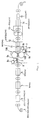
- the method of manufacturing the battery can-forming plate of the first embodiment is carried out in the procedure shown in Fig. 1.
- a hot-rolled steel plate 1 namely a hot coil
- a metal layer nickel layer in the first embodiment
- the hot-rolled plate 1 having a thickness 1mm - 6mm is passed through an acid treatment device 3 to remove oxidized scale formed on both surfaces thereof. Then, the hot rolled plate 1 is introduced into a rinse tank 4 to wash it. Then, it is introduced into a drying oven 5 to dry it.
- the hot rolled plate 1 is successively transported to a roll coater (metal-coating device) 6.
- paste 7 consisting of metal powder and screen oil or a binder added thereto is stored in tanks 8 and 8, and rotation rollers 9a and 9a whose lower portions are immersed in the paste are in contact with each of a pair of paste-applying rollers 10A and 10B.
- the paste-applying rollers 10A and 10B are positioned vertically with a hot coil transport path extending therebetween.
- the paste 7 supplied from the tanks 8 and 8 to the surface of the paste-applying rollers 10A and 10B through the rotation rollers 9a and 9a, respectively is applied to the upper and lower surfaces of the hot coil 1.
- Rolls 9b and 9b are in contact with the rotation rolls 9a and 9a, respectively to drop excess paste.
- Ni powder having a diameter of 0.3 ⁇ m - 10 ⁇ m or a mixture of the nickel powder and powder of other metal is used in the first embodiment.
- the metal mixed with the Ni are selected from Al, In, Ca, Ag, Ge, Co, Sn, Sr, Se, Pb, Ba, Bi, Be, B, Mn, P, Cr, Si, C, Cu, Fe, Zn, La, W, Ti, Mo, Ga and alloy thereof or mixture two or more of the metals.
- the powder of these metals may be particulate, scaly or flake-shaped, scaly or flake-shaped metal powder can be preferably used.
- the metal powder which can be used to coat both surfaces of the hot roiled plate 1 is not limited to the Ni powder and a mixture of the Ni powder and powder of other metal.
- the powder of the above-listed metals may be used.
- the amount of the above metal powder which is applied to the hot rolled plate 1 is set to 13g - 640g/m 2 .
- the metal powder and the screen oil are mixed with each other at 50% - 75% of the metal powder and 50% - 25% of the screen oil.
- Ordinary organic binder resin may be used instead of the screen oil.
- the method of applying the paste 7 consisting of the metal powder and the screen oil to the hot rolled plate 1 is not limited to the method using the roll coater, but other methods can be appropriately adopted.
- the hot rolled plate 1 After the paste 7 consisting of the metal powder and the screen oil is applied to the upper and lower surfaces of the hot rolled plate 1, the hot rolled plate 1 is introduced into a drying oven 11 and then into an annealing oven 12. In the annealing oven 12, the metal powder is sintered at 600°C - 900°C for 1 - 30 minutes in a deoxidizing atmosphere (N 2 : 25% - 99%, H 2 ; 75%- 1%).
- the screen oil (or binder) is thermally decomposed and removed by continuous annealing in the annealing oven 12, and Ni (and other metal mixed with Ni) on the both surfaces of the steel plate is reduced by the temperature and the deoxidizing gas.
- the plate 1 is passed through a pressure roll 13 at the normal temperature - 500°C to roll them at rolling rate of 0.3% - 10%.
- the rolling enhances the degree of the adhesion of the Ni powder to both surfaces of the iron of the steel plate.
- the plate 1 is introduced into an annealing oven 14 to anneal at 600°C - 900°C for 1 - 2 minutes to form a diffusion layer between the iron of the steel plate and the Ni layer or the layer of the mixture of Ni and other metal. Then, the plate 1 is taken out from the annealing oven 14 and introduced into a cooling oven 15 to cool so that the temperature of the plate is reduced at 60°C.
- the plate having the metal layer formed on both surfaces thereof is wound as a coil 2.
- the plate having the metal (Ni) layer formed on its surface and rewound from coil 2 is introduced into a cold rolling device to roll the plate at rolling rate of 80% - 90% until the thickness of the plate is 103% - 101% of the predetermined thickness of a final product.
- the plate is introduced into an annealing oven for annealing (550°C - 800°C, 24 hours - 48 hours) by the batch or for successive annealing (600°C - 900°C, 0.5 minutes - 3 minutes) in a deoxidizing atmosphere.
- the plate After the plate is annealed, the plate is rolled by a pair of skin pass rollers at rolling rate of 0.3% - 3% so that a thickness of the plate, which is used as a battery can-forming plate, become 0.1mm-o.8mm required. Then the plate is wound as coil.
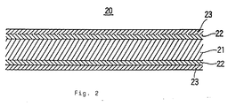
- a Ni-plated layer (or layer of mixture of Ni and other metal) 23 is formed on either surface of a steel plate 21 through a diffusion layer 22.
- the thickness of the steel plate 21 is 0.1mm - 0.8mm.
- the thickness of the diffusion layer 22 is 0.1 ⁇ m - 3 ⁇ m.
- the thickness of the Ni-plated layer 23 formed on both surfaces of the steel plate 21 is 1 ⁇ m - 5 ⁇ m.
- a hot-rolled steel plate (hot coil) having a thickness of 1.66mm was acid-treated to remove oxidized scale. Then, the hot coil was washed with water and dried. Then, 100 parts by weight of Ni powder (consisting of powder having diameter 2 - 5 ⁇ m contained at 80% and powder having diameter 0.5 ⁇ m contained at 20%) and 100 parts by weight of screen oil were kneaded to obtain paste. The paste was applied by a roll coater to either surface of the plate such that either surface was coated with 195g/m 2 of the Ni powder. Then, the plate was annealed in a deoxidizing gas consisting of N 2 at 80% and H 2 at 20% for three minutes at 800°C.
- the plate was successively rolled in a reducing atmosphere at 400°C at a rolling rate of 3%. Thereafter, the plate was annealed again in a reducing atmosphere at 800°C for two minutes. After the plate was cooled to adjust the temperature of the steel plate to 60°C, it was taken out to the atmospheric air. The thickness of the plate was 1.65mm at this time,
- the hot-rolled plate having a thickness of 1.65mm and having a Ni layer formed on either surface of the steel plate was cold-rolled at a rolling rate 84.6% to adjust the thickness thereof to 0.255m. Thereafter, the cold-roiled plate was annealed successively for one minute at 700°C in a reducing atmosphere. Then, the cold-rolled plate was rolled by a skin pass roller at a rolling rate of 2% to obtain a final product, namely, a battery can-forming plate having a thickness of 0.25mm.
- the thickness of the Ni layer was 2.9 ⁇ m and that of the diffusion layer was 1.2 ⁇ m.
- a battery can-forming plate was manufactured.
- Metal powder consisting of Ni:97.9%, Fe;1.0%, Co:0.5%, C:0.2%, and Si:0.4% was used.
- Fig. 3 shows the second embodiment of the present invention.
- a metal layer consisting of Ni powder is formed on the surface of the hot-rolled plate (hot coil).
- the second embodiment is different from the first embodiment in that the Ni powder was applied to the surface of the hot-rolled plate not in the form of paste but spread thereon.
- the thickness of a metal powder layer is adjusted to a predetermined one by a doctor knife.
- the metal layer consisting of the Ni powder is also formed on the hot-rolled plate in the second embodiment. But needless to say, the above-listed metal powders which are used in the first embodiment may be used in the second embodiment.
- the method of spreading metal powder is not limited to a specific method, but a sieve may be used to spread it or a shoot may be used to spread it between a pair of rollers.
- a hot-rolled steel plate 1 is introduced into an acid treatment device 3 to remove oxized scale from the surface of the plate. Then, the plate 1 is introduced into a rinse tank 4 to wash it with water and is dried in a drying oven 5. Then, the plate 1 is successively transported to a metal spreading device 30 in which the metal powder is spread on the upper surface of the plate 1 by using a spreading machine 33, then the thickness of the metal powder layer is adjusted to a predetermined thickness by a doctor knife 31. Then, the plate 1 is passed between a pair of compression rollers 32a and 32b vertically located to compress the spread metal powder.
- the plate 1 is introduced into an annealing oven 12 to sinter the metal powder at 600°C - 900°C for one minute - 30 minutes in a deoxidizing atmosphere (N 2 : 25% - 99%, H 2 : 75% - 1%). Successively, the plate 1 is rolled at rolling rate of 0.3% - 10% in a rolling machine 13, then it is introduced into a cooling oven 34.
- the plate 1 is turned upside down to transport it with the lower surface thereof at the upper side thereof.
- the metal powder is deposited on the lower surface of the plate 1 in the same method as that used to deposit it to the upper surface thereof. That is, the plate 1 is introduced into a metal spreading device 30' to spread the metal powder to the lower surface thereof by a spreading machine 33'. Then, the thickness of the metal powder layer is adjusted to a required one by a doctor knife 31'. Then, the plate 1 is passed between a pair of compression rollers 32a' and 32b' vertically arranged to compress the metal powder.
- the plate 1 is introduced into an annealing oven 12' to sinter the metal powder at 600°C - 900°C for 1 - 30 minutes in a deoxidizing atmosphere (N 2 : 25% - 99%, H 2 : 75% - 1%). Then, the plate 1 is rolled at rolling rate of 0.3% - 10% in a rolling machine 13' and then, introduced into an annealing oven 35 and a cooling oven 36 to adjust the temperature of the steel plate to 60°C.
- the plate having the Ni layer formed on both surfaces thereof is wound around a roll as a coil 2.
- the plate rewound from the coil 2 is introduced into a cold rolling device to roll it at rolling rate of 80% - 90% until the plate is rolled to 103% - 101% of the predetermined thickness of a final product.
- the plate After the plate is cold-rolled, the plate is introduced into an annealing oven for annealing (550°C - 800°C, 24 hours - 48 hours) by the batch or for successive annealing (600°C - 900°C, 0.5 minutes - 3 minutes) in a deoxidizing atmosphere. After the plate is annealed, the plate is rolled by a skin pass roller at rolling rate of 0.3% - 3% so as to be a required thickness of 0.1mm -0.8mm. Then, the plate used a battery can-forming plate 20 is wound as a coil. Referring to Fig.
- a Ni plated layer (or layer of mixture of Ni and other metal) 23 is formed on either surface of a steel plate 21 through a diffusion layer 22.
- the thickness of the steel plate 21 is 0.1mm - 0.8mm.
- the thickness of the diffusion layer 22 is 0.1 ⁇ m - 3 ⁇ m.
- the thickness of the Ni-plated layer 23 formed on both surfaces of the steel plate 21 is 1 ⁇ m - 5 ⁇ m.
- Slab formed by casting was hot-rolled to form a hot coil (a hot-rolled steel plate) having a thickness of 2.0mm. Then, oxidized scale was removed from the hot-rolled plate by acid treatment. Then, the hot-rolled plate was washed with water and dried. Then, using a spreading machine, mixed metal powder consisting of Ni:98.7%, Fe:0,8%, B:0.2%, Ag:0.1%, and Mn:0.2% was spread on the surface of the hot-rolled plate at 180g/m 2 , and then, the thickness of a metal powder layer was adjusted by a doctor knife.
- the plate was annealed at 850°C for three minutes in a deoxidizing gas consisting of N 2 at 80% and H 2 at 20%. Then, the plate was successively rolled at a rolling rate of 1% at 400°C in a reducing atmosphere. Then, the plate was turned upside down to spread mixed metal power to the lower surface thereof by using a spreading machine in a method similar to the above, Then, the thickness of the metal powder layer was adjusted to a required one by a doctor knife. Then, the plate was annealed at 850°C for three minutes in a reducing atmosphere. Then, the plate was successively rolled at a rolling rate of 1% in a reducing atmosphere at 400°C by a rolling machine.
- the plate was annealed again at 800°C for two minutes in a reducing atmosphere. After the plate was cooled to adjust the temperature of the steel plate to 60°C, it was taken out to the atmospheric air. The thickness of the plate was 1.99mm at this time.
- the plate which having a thickness of 1.99mm and having the Ni alloy layer formed on the surface thereof was cold-rolled at a rolling rate of 84.6% to adjust the thickness thereof to 0.306m. Thereafter, the plate was annealed successively for one minute at 750°C in a reducing atmosphere. Then, the plate was rolled by a skin pass roller at a rolling rate of 2% to obtain a final product, namely, a battery can-forming plate having a thickness of 0.3mm.
- the thickness of the Ni alloy layer was 2.8 ⁇ m and that of the diffusion layer was 1.6 ⁇ m.
- Fig. 4 shows the third embodiment of the present invention.
- the third embodiment is different from the first and second embodiments in that, instead of forming a metal layer consisting of metal powder on the surface of the hot-rolled steel plate, a plated layer (in the third embodiment, Ni-plated layer) is formed thereon by electroplating.
- a hot-rolled steel plate1 is introduced into an acid treatment device 3 to remove oxidized scale formed on the surface thereof. Then, the hot coil 1 was washed with water in a rinse tank 4. After the plate 1 is introduced into a neutralizing device 40, it is introduced into a rinse tank 41. Then, it is introduced into a plating tank 42 to plate both surfaces of the hot-rolled steel plate 1. After the hot-rolled steel plate 1 is electroplated in the plating tank 42, it is washed with water in a rinse tank 43. Then, it is introduced into a drying oven 44 to dry it.
- the plate 1 having the metal plated thereon is annealed in a reducing atmosphere at 600°C - 900°C. Then, the plate 1 is rolled at the normal temperature - 500°C at rolling rate of 0.3% - 5% in a rolling machine 46. Thereafter, the plate 1 is introduced into a cooling oven 47 to cool it. As a result, a plate having the Ni-plated layer thereon is formed.
- the steel plate is thick and the plated layer is also thick because the steel plate and the plated layer are cold-rolled after the steel plate is plated. Thus, the plated layer is liable to be separated from the steel plate. In order to prevent this, the diffusion layer is formed between the steel plate and the plated metal layer.
- the hot-rolled plate having the Ni plated layers on both surfaces thereof is introduced into a cold rolling device to roll it at rolling rate of 80% - 90%, until the thickness of the plate is 103% - 101% of the predetermined thickness of a final product.
- the plate After the plate is cold-rolled, the plate is introduced into an annealing oven for annealing (550°C - 800°C, 24 hours - 48 hours) by the batch or successive annealing (600°C - 900°C, 0.5 minutes - 3 minutes) in a deoxidizing atmosphere. After the plate is annealed, the plate is rolled by a skin pass roller at rolling rate of 0.3% - 3% so as to be a required thickness of 0.1mm - 0.8mm, then the plate used for a battery can-forming plate is wound as a coil. Referring to Fig.
- a Ni-plated layer (or layer of mixture of Ni and other metal) 23 is formed on either surface of a steel plate 21 through a diffusion layer 22.
- the thickness of the steel plate 21 is 0.1mm - 0.8mm.
- the thickness of the diffusion layer 22 is 0.1 ⁇ m - 3 ⁇ m.
- the thickness of the Ni-plated layer 23 is 1 ⁇ m - 5 ⁇ m.
- Iron slab formed by casting was hot-rolled to form a hot -rolled plate (hot coil) having a thickness of 2.67mm. Then, oxidized scale was removed from the plate by acid treatment. Then, the plate was washed with water, neutralized, and washed. Then, the hot coil was Ni-plated in Watts bath to form a nickel-plated layer having a thickness of 22 ⁇ m on each of both surfaces (44 ⁇ m on both surfaces) thereof.
- the plate having the nickel-plated layer formed thereon was annealed in a deoxidizing gas consisting of N 2 at 80% and H 2 at 20% at 750°C for three minutes. Then, using a rolling machine, the hot coil was successively rolled in a reducing atmosphere at 400°C at a rolling rate of 2%. After the plate was cooled to adjust the temperature of the steel plate 60°C, it was taken out to the atmospheric air. The thickness of the plate was 2.66mm at this tune.
- the plate having a thickness of 2.66mm and the Ni layer formed on the surface thereof was cold-rolled at a rolling rate of 84.6% to adjust the thickness thereof to 0.41m. Thereafter, the plate was annealed by the batch in a reducing atmosphere at 600°C for 24 hours. Then, the plate was rolled by a skin pass roller at a rolling rate of 2.5% to obtain a final product, namely, a battery can-forming plate having a thickness of 0.4mm.
- the thickness of the Ni layer was 3 ⁇ m and that of the diffusion layer was 1.4 ⁇ m.
- the thickness of the battery can-forming plate manufactured by the method of the first through fourth experiments and the components thereof are as shown in table 2 shown below.
- the mechanical characteristics of each battery can-forming plate, namely, the YP (yield point), TS (tensile strength), EL (elongation), HR-30T (hardness) thereof, and the thickness of the diffusion layer thereof are also as shown in table 2.
- the yield point, tensile strength, and elongation of the battery can-forming plate of each of the first through fourth experiments were almost equal to those of a conventional battery can-forming plate manufactured by plating a cold-rolled steel plate having a final thickness and those of a battery can-forming plate manufactured by plating a cold-rolled steel plate and then annealing and rolling it to have a final thickness.
- the manufacturing method of the present invention in which metal layer on the hot-rolled steel plate (hot coil) is formed by plating it directly or spreading metal powder thereon or coating metal powder on the hot-rolled steel plate, is more productive and much less costly than the conventional manufacturing method. Further, it was confirmed that the battery can-forming plate of the present invention have a quality similar to that of the battery can-forming plate manufactured by the conventional method.
- battery cans were formed of the battery can-forming plate of the first through fourth experiments of the present invention and that of the conventional examples 1 and 2 by using press drawing. That is, the battery cans were formed by using three kinds of drawing processes, namely, transfer drawing, DI (drawing and ironing), and drawing in combination of transfer drawing and DI.
- the battery can-forming plates were bent by 360° three times to visually inspect the degree of separation of the metal layer formed on the surface of the steel plate.
- Table 3 shown below shows the result of the corrosion test, the press drawing property test, and the separation property test.
- X indicates “worst”
- ⁇ indicates “worse”
- O indicates “good”
- o ⁇ indicates "best”.
- the separation property means the degree of adhesion between the steel plate and the nickel layer formed thereon. "Good separation” means that the steel plate and the nickel layer are not separated from each other but stably kept in an adhesive state.
- the battery can-forming plate of each of the first through fourth experiments of the present invention was good in the corrosion resistance, the press drawing property, and the separation property and excellent in the separation property.
- the battery can-forming plate of the present invention can be manufactured by various processes as shown in Figs. 5A, 5B, 5C, and 5D; Figs. 6A, 6B, 6C, and 6D; Figs. 7A, 7B, and 7C; and Figs. 8A and 8B.
- the metal layer which is formed on either surface of the hot-rolled plate consists of the same kind of metal
- the layer which is formed on the upper surface thereof and that which is formed on the lower surface thereof may consist of different kinds of metal.
- a Ni-plated layer may be formed on one surface thereof, whereas a layer of aluminum powder may be formed on the other surface thereof.
- metal layers may be laminated on the surface of a steel plate.
- a layer of aluminum powder may be formed on the surface of the nickel-plated layer.
- two or more metal layers may be laminated on each surface of the plate.
- the battery cans were formed by using the known battery can-forming method, namely, transfer drawing, DI or drawing in combination of transfer drawing and DI. As confirmed in the test, because the battery can-forming plate of the present invention is preferable in press drawing property, it is superior in processability as well.
- the present invention replacing the conventional method of cold-rolling a hot-rolled steel plate (hot coil) to make the thickness thereof thin and plating the cold-rolled steel plate, metal powder is spread on the hot-roiled steel plate or applied thereto in the form of slurry to form a metal layer thereon. Therefore, the length per unit weight in the hot-rolled steel plate is shorter than that of the steel plate which is cold-rolled to a required thickness.
- the method of the present invention allows the surface area of the steel plate which is treated to be smaller than that of the steel plate which is treated by the conventional method, thus forming the metal layer consisting of metal powder or the plated metal layer in a short period of time. In result, the method of the present invention enhances the productivity, thus accomplishing a great deal of surface-treating operation in a short period of time.
- the method of the present invention allows the battery can-forming plate to be manufactured with reducing cost much.
- the plated layer or/and the metal layer consisting of metal powder are formed on the surface of the steel plate, the only small area may be surface- treated. It allows the total manufacturing cost can be reduced by about 25% compared to that of the conventional method of surface-treating the cold-rolled steel plate.
- a battery can-forming plate of the same thickness and width that the conventional battery can-forming plate has can be manufactured with reducing the required period to about 1/7 of the period by the conventional manufacturing method (after steel plate is hot-rolled, it is cold-rolled, and then, plated).
Landscapes
- Chemical & Material Sciences (AREA)
- Chemical Kinetics & Catalysis (AREA)
- Electrochemistry (AREA)
- General Chemical & Material Sciences (AREA)
- Materials Engineering (AREA)
- Engineering & Computer Science (AREA)
- Mechanical Engineering (AREA)
- Metallurgy (AREA)
- Organic Chemistry (AREA)
- Inorganic Chemistry (AREA)
- Sealing Battery Cases Or Jackets (AREA)
- Heat Treatment Of Sheet Steel (AREA)
- Solid-Phase Diffusion Into Metallic Material Surfaces (AREA)
- Other Surface Treatments For Metallic Materials (AREA)
Applications Claiming Priority (3)
| Application Number | Priority Date | Filing Date | Title |
|---|---|---|---|
| JP154185/97 | 1997-06-11 | ||
| JP9154185A JPH111779A (ja) | 1997-06-11 | 1997-06-11 | 電池缶形成材料の製造方法および該方法により製造された電池缶形成材料 |
| CA002240463A CA2240463A1 (fr) | 1997-06-11 | 1998-06-12 | Methode de fabrication d'une plaque destinee a etre l'enveloppe metallique d'une pile et ladite plaque |
Publications (1)
| Publication Number | Publication Date |
|---|---|
| EP0884402A1 true EP0884402A1 (fr) | 1998-12-16 |
Family
ID=31496504
Family Applications (1)
| Application Number | Title | Priority Date | Filing Date |
|---|---|---|---|
| EP98110727A Ceased EP0884402A1 (fr) | 1997-06-11 | 1998-06-10 | Méthode de fabrication d'une tôle pour formation de boítiers de pile et tôle obtenu par cette méthode |
Country Status (5)
| Country | Link |
|---|---|
| US (1) | US6153027A (fr) |
| EP (1) | EP0884402A1 (fr) |
| JP (1) | JPH111779A (fr) |
| CN (1) | CN1208969A (fr) |
| CA (1) | CA2240463A1 (fr) |
Cited By (2)
| Publication number | Priority date | Publication date | Assignee | Title |
|---|---|---|---|---|
| DE102005013103A1 (de) * | 2005-03-18 | 2006-09-28 | Sms Demag Ag | Kontrollierte Dickenreduktion bei schmelztauchbeschichtetem warmgewalztem Stahlband und hierbei eingesetzte Anlage |
| WO2024022971A3 (fr) * | 2022-07-25 | 2024-03-21 | Wickeder Westfalenstahl Gmbh | Boîtier pour un élément électronique, de préférence un élément de batterie ou un condensateur |
Families Citing this family (23)
| Publication number | Priority date | Publication date | Assignee | Title |
|---|---|---|---|---|
| JP3481797B2 (ja) * | 1996-10-03 | 2003-12-22 | 片山特殊工業株式会社 | 電池電極用基板の製造方法および電池電極用基板 |
| JP3724955B2 (ja) * | 1997-08-29 | 2005-12-07 | 住友電気工業株式会社 | 二次電池用電槽缶 |
| JP3594285B2 (ja) * | 1998-05-21 | 2004-11-24 | 東洋鋼鈑株式会社 | 電池ケース用表面処理鋼板、それを用いた電池ケース、それらの製造方法及び電池 |
| KR100580447B1 (ko) * | 1999-11-30 | 2006-05-15 | 현대자동차주식회사 | 내마모용 알루미늄-실리콘 박판 제조방법 및 그 제조장치 |
| JP2001313008A (ja) * | 2000-04-28 | 2001-11-09 | Matsushita Electric Ind Co Ltd | 電池缶およびその製造方法並びに電池 |
| US6986185B2 (en) * | 2001-10-30 | 2006-01-17 | Applied Materials Inc. | Methods and apparatus for determining scrubber brush pressure |
| KR100696929B1 (ko) * | 2002-04-22 | 2007-03-20 | 도요 고한 가부시키가이샤 | 전지 케이스용 표면 처리 강판, 전지 케이스 및 그것을사용한 전지 |
| JP4399232B2 (ja) * | 2003-10-17 | 2010-01-13 | Fdkエナジー株式会社 | アルカリ電池 |
| JP4798955B2 (ja) * | 2004-02-13 | 2011-10-19 | 東洋鋼鈑株式会社 | 電池容器用めっき鋼板、その電池容器用めっき鋼板を用いた電池容器、およびその電池容器を用いた電池 |
| JP4698205B2 (ja) * | 2004-11-11 | 2011-06-08 | 東洋鋼鈑株式会社 | 電池ケース用鋼板、電池ケース用表面処理鋼板、電池ケースおよび電池 |
| JP4836612B2 (ja) * | 2006-03-03 | 2011-12-14 | 株式会社東芝 | 非水電解質電池および電池パック |
| DE102007013739B3 (de) * | 2007-03-22 | 2008-09-04 | Voestalpine Stahl Gmbh | Verfahren zum flexiblen Walzen von beschichteten Stahlbändern |
| CN101683656B (zh) | 2008-09-27 | 2012-05-30 | 宝山钢铁股份有限公司 | 薄带连铸连轧生产复合钢板的方法 |
| PL2290133T3 (pl) * | 2009-08-25 | 2012-09-28 | Thyssenkrupp Steel Europe Ag | Sposób wytwarzania elementu stalowego z antykorozyjną powłoką metalową i element stalowy |
| WO2011083562A1 (fr) * | 2010-01-08 | 2011-07-14 | 東洋鋼鈑株式会社 | Feuille d'acier plaquée au ni avec excellente aptitude au pressage pour boîte de pile ou batterie |
| JP5361939B2 (ja) * | 2011-05-09 | 2013-12-04 | 株式会社東芝 | 非水電解質電池および電池パック |
| JP5361940B2 (ja) * | 2011-05-09 | 2013-12-04 | 株式会社東芝 | 非水電解質電池および電池パック |
| JP6384245B2 (ja) * | 2014-10-02 | 2018-09-05 | 株式会社村田製作所 | 溶接部の防錆方法、防錆シート |
| JP6810536B2 (ja) * | 2016-04-25 | 2021-01-06 | 臼井国際産業株式会社 | 金属材およびその製造方法 |
| JP7444357B2 (ja) | 2017-10-23 | 2024-03-06 | エルジー エナジー ソリューション リミテッド | 表面粗度が改善された円筒型電池ケースの製造方法 |
| CN112639171A (zh) * | 2018-08-31 | 2021-04-09 | 东洋钢钣株式会社 | 电池容器用金属板和该电池容器用金属板的制造方法 |
| CN111293246B (zh) * | 2020-02-21 | 2022-05-20 | 苏州宝优际科技股份有限公司 | 基于热成型工艺的新能源汽车动力电池壳体生产方法 |
| CN114951278B (zh) * | 2022-05-25 | 2024-11-01 | 湘潭大学 | 一种直接通过机械加工制备的Zn-Se基合金及其制备方法和应用 |
Citations (5)
| Publication number | Priority date | Publication date | Assignee | Title |
|---|---|---|---|---|
| US4189522A (en) * | 1975-08-08 | 1980-02-19 | Daido Metal Company, Ltd. | Multi-layer sliding material and method for manufacturing the same |
| JPH05311389A (ja) * | 1992-05-13 | 1993-11-22 | Sumitomo Metal Ind Ltd | 分散メッキ鋼板の製造方法 |
| EP0725453A1 (fr) * | 1993-10-22 | 1996-08-07 | TOYO KOHAN Co., Ltd | Feuille d'acier traite en surface pour boitier de batterie et boitier de batterie produit a l'aide de ladite feuille |
| EP0741424A1 (fr) * | 1995-05-05 | 1996-11-06 | Rayovac Corporation | Pile métal-air dont les pÔles du boîtier présentant des parois fines |
| US5603782A (en) * | 1993-06-04 | 1997-02-18 | Katayama Special Industries, Ltd. | Battery can, sheet for forming battery can, and method for manufacturing sheet |
Family Cites Families (2)
| Publication number | Priority date | Publication date | Assignee | Title |
|---|---|---|---|---|
| US857041A (en) * | 1903-10-05 | 1907-06-18 | Edison Storage Battery Co | Can or receptacle for storage batteries. |
| JP3045612B2 (ja) * | 1992-06-22 | 2000-05-29 | 東洋鋼鈑株式会社 | 高耐食性ニッケルめっき鋼帯およびその製造法 |
-
1997
- 1997-06-11 JP JP9154185A patent/JPH111779A/ja not_active Withdrawn
-
1998
- 1998-06-10 EP EP98110727A patent/EP0884402A1/fr not_active Ceased
- 1998-06-11 CN CN98109877A patent/CN1208969A/zh active Pending
- 1998-06-11 US US09/095,896 patent/US6153027A/en not_active Expired - Fee Related
- 1998-06-12 CA CA002240463A patent/CA2240463A1/fr not_active Abandoned
Patent Citations (5)
| Publication number | Priority date | Publication date | Assignee | Title |
|---|---|---|---|---|
| US4189522A (en) * | 1975-08-08 | 1980-02-19 | Daido Metal Company, Ltd. | Multi-layer sliding material and method for manufacturing the same |
| JPH05311389A (ja) * | 1992-05-13 | 1993-11-22 | Sumitomo Metal Ind Ltd | 分散メッキ鋼板の製造方法 |
| US5603782A (en) * | 1993-06-04 | 1997-02-18 | Katayama Special Industries, Ltd. | Battery can, sheet for forming battery can, and method for manufacturing sheet |
| EP0725453A1 (fr) * | 1993-10-22 | 1996-08-07 | TOYO KOHAN Co., Ltd | Feuille d'acier traite en surface pour boitier de batterie et boitier de batterie produit a l'aide de ladite feuille |
| EP0741424A1 (fr) * | 1995-05-05 | 1996-11-06 | Rayovac Corporation | Pile métal-air dont les pÔles du boîtier présentant des parois fines |
Non-Patent Citations (1)
| Title |
|---|
| PATENT ABSTRACTS OF JAPAN vol. 018, no. 128 (C - 1174) 2 March 1994 (1994-03-02) * |
Cited By (5)
| Publication number | Priority date | Publication date | Assignee | Title |
|---|---|---|---|---|
| DE102005013103A1 (de) * | 2005-03-18 | 2006-09-28 | Sms Demag Ag | Kontrollierte Dickenreduktion bei schmelztauchbeschichtetem warmgewalztem Stahlband und hierbei eingesetzte Anlage |
| US8163348B2 (en) | 2005-03-18 | 2012-04-24 | Sms Siemag Aktiengesellschaft | Controlled thickness reduction for hot-dip coated, hot-rolled steel strip and installation used in this process |
| US8703242B2 (en) | 2005-03-18 | 2014-04-22 | Sms Siemag Aktiengesellschaft | Controlled thickness reduction for hot-dip coated, hot-rolled steel strip and installation used in this process |
| WO2024022971A3 (fr) * | 2022-07-25 | 2024-03-21 | Wickeder Westfalenstahl Gmbh | Boîtier pour un élément électronique, de préférence un élément de batterie ou un condensateur |
| US12438218B2 (en) | 2022-07-25 | 2025-10-07 | Wickeder Westfalenstahl Gmbh | Housing for an electronic element, preferably a battery cell or a capacitor |
Also Published As
| Publication number | Publication date |
|---|---|
| US6153027A (en) | 2000-11-28 |
| JPH111779A (ja) | 1999-01-06 |
| CN1208969A (zh) | 1999-02-24 |
| CA2240463A1 (fr) | 1999-12-12 |
Similar Documents
| Publication | Publication Date | Title |
|---|---|---|
| EP0884402A1 (fr) | Méthode de fabrication d'une tôle pour formation de boítiers de pile et tôle obtenu par cette méthode | |
| EP0629009B1 (fr) | Boîtier de batteries, tÔle pour former un boîtier de batteries et méthode pour manufacturer une telle tÔle | |
| KR100292173B1 (ko) | 전지용 표면 처리 강판과 그 제조방법, 전지 케이스, 및 그 전지 케이스를 이용한 전지 | |
| US6165640A (en) | Battery can-forming plate and battery can | |
| RU2355788C2 (ru) | Стальной лист с высоким содержанием алюминия и способ его производства | |
| KR100518143B1 (ko) | 전지 케이스용 표면처리강판 및 전지 케이스 | |
| CN112368425A (zh) | 表面处理钢板和表面处理钢板的制造方法 | |
| US6613163B1 (en) | Steel band with good forming properties and method for producing same | |
| KR20210016462A (ko) | 표면 처리 강판 및 표면 처리 강판의 제조 방법 | |
| US5849423A (en) | Zinciferous plated steel sheet and method for manufacturing same | |
| EP0945209B1 (fr) | Tôle pour formation de boitiers de pile et méthode de fabrication de cette tôle | |
| JP4690558B2 (ja) | 電池特性の優れたアルカリマンガン電池正極缶用Niメッキ鋼板および製造方法 | |
| EP1352994B1 (fr) | Plaque d'acier plaquee ni pour gaine anodique d'element de pile seche en manganese alcalin | |
| JPS6136595B2 (fr) | ||
| EP0900857B1 (fr) | Tole d'acier galvanise a chaud presentant peu de defauts par suite d'un placage defectueux, ainsi que d'excellentes caracteristiques d'adherence de depot par contact, et son procede de production | |
| KR19990006852A (ko) | 전지 캔 형성재료의 제조방법 및 이 방법으로 제조된 전지 캔 형성재료 | |
| JP2013170308A (ja) | プレス成形性に優れたリチウムイオン電池ケース用表面処理鋼板及びその製造方法 | |
| JP2004095497A (ja) | アルカリ電池正極缶用Niメッキ鋼板および製造方法 | |
| JP3664046B2 (ja) | アルカリマンガン電池正極缶用Niメッキ鋼板の製造方法 | |
| JP2002208382A (ja) | アルカリマンガン電池正極缶用Niメッキ鋼板 | |
| EP4582599A1 (fr) | Tôle d'acier revêtue de nickel traitée thermiquement pour boîtier de batterie présentant une excellente résistance à la corrosion de surface présentant une conductivité | |
| JP2001167746A (ja) | 金属板の製造方法および該方法により製造された金属板 | |
| JPS60155685A (ja) | 耐食性及びシ−ム溶接性に優れた容器用表面処理鋼板の製造方法 | |
| JPH11131285A (ja) | 溶接缶用めっき鋼板およびその製造方法 | |
| JP2003277974A (ja) | 電池缶用Niメッキ鋼板の製造方法 |
Legal Events
| Date | Code | Title | Description |
|---|---|---|---|
| PUAI | Public reference made under article 153(3) epc to a published international application that has entered the european phase |
Free format text: ORIGINAL CODE: 0009012 |
|
| AK | Designated contracting states |
Kind code of ref document: A1 Designated state(s): AT BE CH DE FR GB LI |
|
| AX | Request for extension of the european patent |
Free format text: AL;LT;LV;MK;RO;SI |
|
| 17P | Request for examination filed |
Effective date: 19990519 |
|
| AKX | Designation fees paid |
Free format text: AT BE CH DE FR GB LI |
|
| GRAG | Despatch of communication of intention to grant |
Free format text: ORIGINAL CODE: EPIDOS AGRA |
|
| 17Q | First examination report despatched |
Effective date: 20020117 |
|
| STAA | Information on the status of an ep patent application or granted ep patent |
Free format text: STATUS: THE APPLICATION HAS BEEN REFUSED |
|
| 18R | Application refused |
Effective date: 20020713 |