EP0884404A2 - Vorrichtung zur Elektroplattierung eines Tiefdruckzylinders unter Verwendung von Ultraschallenergie - Google Patents
Vorrichtung zur Elektroplattierung eines Tiefdruckzylinders unter Verwendung von Ultraschallenergie Download PDFInfo
- Publication number
- EP0884404A2 EP0884404A2 EP97250241A EP97250241A EP0884404A2 EP 0884404 A2 EP0884404 A2 EP 0884404A2 EP 97250241 A EP97250241 A EP 97250241A EP 97250241 A EP97250241 A EP 97250241A EP 0884404 A2 EP0884404 A2 EP 0884404A2
- Authority
- EP
- European Patent Office
- Prior art keywords
- cylinder
- plating
- tank
- plating solution
- transducer element
- Prior art date
- Legal status (The legal status is an assumption and is not a legal conclusion. Google has not performed a legal analysis and makes no representation as to the accuracy of the status listed.)
- Granted
Links
Images




Classifications
-
- C—CHEMISTRY; METALLURGY
- C25—ELECTROLYTIC OR ELECTROPHORETIC PROCESSES; APPARATUS THEREFOR
- C25D—PROCESSES FOR THE ELECTROLYTIC OR ELECTROPHORETIC PRODUCTION OF COATINGS; ELECTROFORMING; APPARATUS THEREFOR
- C25D5/00—Electroplating characterised by the process; Pretreatment or after-treatment of workpieces
- C25D5/20—Electroplating using ultrasonic waves
-
- C—CHEMISTRY; METALLURGY
- C25—ELECTROLYTIC OR ELECTROPHORETIC PROCESSES; APPARATUS THEREFOR
- C25D—PROCESSES FOR THE ELECTROLYTIC OR ELECTROPHORETIC PRODUCTION OF COATINGS; ELECTROFORMING; APPARATUS THEREFOR
- C25D5/00—Electroplating characterised by the process; Pretreatment or after-treatment of workpieces
- C25D5/60—Electroplating characterised by the structure or texture of the layers
- C25D5/615—Microstructure of the layers, e.g. mixed structure
- C25D5/617—Crystalline layers
-
- C—CHEMISTRY; METALLURGY
- C25—ELECTROLYTIC OR ELECTROPHORETIC PROCESSES; APPARATUS THEREFOR
- C25D—PROCESSES FOR THE ELECTROLYTIC OR ELECTROPHORETIC PRODUCTION OF COATINGS; ELECTROFORMING; APPARATUS THEREFOR
- C25D7/00—Electroplating characterised by the article coated
- C25D7/04—Tubes; Rings; Hollow bodies
Definitions
- the present invention relates to an apparatus for electroplating a rotogravure cylinder using ultrasonic energy.
- the top edge of the respective baskets are disposed below the surface of the electrolyte bath so as to ensure free circulation of constantly refreshed (i.e. filtered) electrolytic fluid or solution.
- Electrolytic fluid is pumped into the tank from a manifold adjacent to the bottom of one of the baskets, in the direction of cylinder rotation.
- the top of the rotating cylinder to be plated is disposed slightly above the surface level of the electrolytic fluid so that a washing action occurs as the surface of the cylinder breaks across the surface of the electrolyte. Ions move from the copper bars or nuggets through the electrolytic fluid to the surface of the rotating cylinder during the plating process (or in the reverse direction in the deplating process). Where plating is done directly from a plating solution, ions moves directly from the solution to the surface of the rotating cylinder.
- the complete process is comparatively slow, and extra polishing steps may be necessary after plating in order to produce a desirable uniform surface (e.g. roughness on grain structure) on the cylinder.
- the overall efficiency of the process necessary to produce a suitably uniform plated surface on the cylinder can be adjusted either by reducing the current density, which increases the plating time but reduces the number or duration of additional polishing steps, or by increasing the current density, which reduces the plating time but increases the number or duration of additional polishing steps.
- a copper sludge may tend to accumulate on and about the cylinder during the plating process, forming uneven and undesirable copper deposits, typically in areas of low current density (such as furthest apart from the copper cylinder).
- a copper sludge may also build up between the contact surfaces of the titanium baskets or lead contacts. Moreover, other surfaces may become fouled with sludge and other matter.
- Ultrasonic wave energy has been used successfully in surface cleaning applications.
- the long-known advantages in using ultrasonic energy in electroplating have also been described in such articles as "Ultrasonics in the Plating Industry", Plating , pp. 141-47 (March 1967), and “Ultrasonics Improves, Shortens and Simplifies Plating Operations,” MPM , pp. 47-49 (March 1962), both of which are incorporated by reference herein.
- ultrasonic energy may advantageously be employed to improve the quality (e.g. uniformity and consistency of grain structure) of a plating process by providing for uniformity and efficiency of ion movement.
- an apparatus configured to capitalize on the advantages of ultrasonic energy in the electroplating of a rotogravure cylinder. It would also be advantages to have an apparatus configured to use ultrasonic energy in the plating a rotogravure cylinder in order to obtain a more uniform and consistent grain structure on the plated surface of the cylinder through a more efficient process. It would further be advantageous to have a rotogravure cylinder plating apparatus employing ultrasonic energy to eliminate the build-up of copper (or other) sludge during the plating process.
- the present invention relates to an apparatus for electroplating and deplating a rotogravure cylinder out of a plating solution.
- the apparatus includes a plating tank adapted to rotatably maintain the cylinder and to contain a plating solution so that the cylinder is at least partially disposed into the plating solution, a mounting structure mountable within the tank partially on each side of and generally below the cylinder, and a plurality of conductors comprising elongate metallic strips at least partially disposed within the plating solution.
- a current source is electrically connected to the upper portions of the conductor strips and to the cylinder.
- An ultrasonic system introduces wave energy into the plating solution.
- the ultrasonic system includes at least one transducer element mountable within the tank and a power generator adapted to provide electrical energy to the at least one transducer element.
- Apparatus 110 includes a plating tank 12 having side walls 12a and 12b, and walls 12d and 12e, and bottom 12c.
- Plating tank 12 as shown in FIGURE 1 contains an electrolytic fluid (e.g. copper sulfate or the like in an appropriate solution) indicated by reference letter F at a level (indicated by reference letter L) regulated by the height of a weir 72 (e.g. the top of side wall 12b).
- a rotogravure cylinder 20 to be plated (or deplated) is rotatably supported at its ends (e.g.
- Cylinder 20 upon an extending central shaft) to be submerged into the electrolytic fluid approximately one-half to one-third of the cylinder diameter.
- Cylinder 20 is rotatably supported at its ends by bearings within a journal 22, in which it is rotatably driven by a suitable powering device (not shown).
- Cylinder 20, shown in the FIGURES as one of a standard size e.g., having a diameter of approximately 800 to 1500 mm
- Cylinder 20 shown in the FIGURES as one of a standard size (e.g., having a diameter of approximately 800 to 1500 mm), is disposed in close proximity to a basket system 30; according to alternative embodiments cylinders of other diameters may be accommodated.
- the tank system and cylinder mounting and drive system are of a conventional arrangement known to those of ordinary skill in the art of rotogravure cylinder plating.
- apparatus 10 will include a basket system 30 having one or a plurality of basket compartments 32 formed by a series of side and internal dividing walls 31.
- Basket system 30 in any preferred embodiment be disposed into the electrolytic fluid below level 70 of the electrolytic fluid. To ensure complete and constant exchange of the electrolytic fluid, the exterior side walls of basket compartments 32 are maintained below level L, otherwise the flow of electrolytic fluid may stagnate between basket compartments 32 and cylinder 20 and may possibly cause overheating.
- the electrolytic fluid is itself of a composition known to those of ordinary skill in the art of electroplating, for example a solution of 220 to 250 gram/liter copper sulfate and 60 gram/liter sulfuric acid, to fill plating tank 12 to level L.
- basket compartments 32 of concavo-convex basket system 30 contain nuggets 34 of a metallic material such as copper to be plated onto (or deplated from) cylinder 20.
- Basket compartments 32 and partitioning walls 31 are formed from a suitable metallic material, typically titanium, or in an alternative embodiment, from a suitable plastic material such as polypropylene (as shown in FIGURE 7).
- suitable metallic material typically titanium
- suitable plastic material such as polypropylene
- the distance between the anode surface of basket system 30 to the cathode surface of cylinder 20 is approximately 40 to 60 mm.
- basket system 30 does not encompass any substantial portion of the outer perimeter of cylinder 20. (This relationship may vary in alternative embodiments which employ a basket system of a larger size relative to the cylinder.)
- basket system 30 is suspended from a pair of rails 40 extending along walls 12a and 12b of plating tank 12 by a series of hangers, shown as lead anodes 42.
- the ends of rails 40 may be supported by the tank ends or side walls.
- Lead anodes 42 provide electrical connection to rails 40 (e.g. bus bars), across basket system 30 and through basket compartments 32 in a manner so also to provide an electrical connection to electrically-conductive nuggets 34.
- rails 40 e.g. bus bars
- high phosphor copper mini-nuggets preferably 0.04 to 0.06 percent phosphor, are used.
- nuggets 34 are contained in basket compartments 32 with overlaid plastic sheeting 36 (shown cut away in portions to reveal nuggets 34).
- plastic sheeting 36 shown cut away in portions to reveal nuggets 34.
- lead anodes 42 e.g.
- Electrodes 42 serve as the structural supports (i.e. hangers) for basket system 30.
- Lead anodes 42 are mechanically fastened and electrically coupled to current-carrying rails 40 at junctions employing fasteners, shown as bolts 100.
- the inner walls of basket compartments 32 have perforations and the outer walls of basket compartments 32 are solid, except for two rows of holes near their tops which enable the flow of plating solution through basket compartments 32.
- Upper portions 42a of the lead anode strips 42 are dip coated to protect them from the electrolytic fluid; and lower portions 42b of lead anodes 42 are exposed and positioned within basket compartments 32 to maintain electrical contact with copper nuggets 34.
- the packing of copper nuggets 34 around and between lead anodes 42 and cylinder 20 to be plated protects lead anodes 42 against wear.
- the rails are connected to an anode side of a plating power supply (e.g. a current source of known design) and the cylinder is connected to a cathode side of the power supply; for de-plating, the anode-cathode connections are reversed.
- a plating power supply e.g. a current source of known design
- the cylinder is printed out (i.e. after having been plated and etched), it is returned to the plating apparatus and deplated so as to return the copper to the nuggets.
- Transducer elements 50 shown disposed lengthwise along the bottom surface of basket system 30 (e.g. bonded or securely mounted thereto) are ultrasonic transducer elements 50.
- Transducer elements 50 (shown as four elements 50a through 50d in FIGURES 1 through 4 and 7) are electrically coupled to a control system (shown schematically in FIGURE 10) and are provided to introduce ultrasonic wave energy into plating tank 12.
- Transducer elements 50 can be of any variety known in the art. According to a particularly preferred embodiment, the transducer elements are designed to provide for operation in a frequency range of 15 to 30 KHz (cycles). In the exemplary embodiment shown in FIGURE 1, two of the four transducer elements (e.g.
- outer transducer elements 50a and 50b are configured and positioned in relation to basket system 30 as to assist with the plating process directly (e.g. to facilitate consistency of ion migration through the electrolytic fluid); the remaining two transducer elements (e.g. inner transducer elements 50c and 50d) are configured and positioned in relation to basket system 30 as to provide a cleaning function and maintain nuggets 34, cylinder 20 and other elements of and about basket system 30 free of copper sludge and other fouling buildup.
- the electrolytic fluid supply system functions as a closed circuit system.
- a supply of electrolytic fluid F is provided into plating tank 12 by at least one spray bar 62 (two are shown), which consists of a section of pipe or tube extending laterally along or near the bottom of plating tank 12.
- Each spray bar 62 has a series of apertures 62a along its length (as shown at least partially in FIGURE 2) that provide for a constant and relatively well-dispersed flow of electrolytic fluid into plating tank 12 from a holding tank 14 (e.g. a reservoir).
- Holding tank 14 is formed of side walls 14a and 14b, a bottom 14d, a top 14c, and end walls 14d and e, and is disposed beneath plating tank 12 (e.g. top 14c of holding tank 14 matches bottom 12c of plating tank 12) so as to capture any flow of electrolytic fluid travelling over weir 72 in plating tank 12.
- Electrolytic fluid F is maintained at its own level in holding tank 14.
- Electrolytic fluid may build up heat and increase in temperature over time during the plating (or deplating) process and therefore holding tank 14 is equipped with a fluid cooling system 16 (e.g. a suitable heat exchanger for such fluid of a type known in the art).
- electrolytic fluid may need to be heated from an ambient temperature to a higher temperature at the outset of the plating process and therefore holding tank 14 is also equipped with a fluid heating system 18 (e.g. a suitable heat exchanger for such fluid of a type known in the art).
- the temperature regulating system for the plating solution can be coupled to an automatic control system that operates from information obtained by temperature sensors in or near one or both tanks, and to control other parameters that may be monitored during the process, according to known arrangements.
- the electrolytic fluid is constantly being filtered and the ultrasonic system is constantly running.
- the ultrasonic system can be energized to provide for agitation of electrolytic fluid and for cleaning of the basket system (to eliminate metallic sludge) to provide for better contact between the metal nuggets and the titanium basket compartments and lead anodes (or the lead anodes themselves in an embodiment having plastic basket compartments).
- a pair of supply pipes 60 feed spray bars 62 with a supply flow of electrolytic fluid.
- Supply pipes 60 each are coupled to a circulation pump 64 and a filter 66 (configured and operated according to a known arrangement).
- Circulation pumps 64 draw electrolytic fluid F from holding tank 14 into inlets 61 in each of supply pipes 60 and force it under pressure through filters 66 and into spray bars 62 where (having been filtered) it is reintroduced through apertures 62a into plating tank 12 for the electroplating process.
- Each of spray bars 62 extends along the bottom of plating tank 12, rising horizontally from holding tank 14 and turning at an elbow 68 to run horizontally along and beneath basket system 30.
- the apparatus could include one pump and filter coupled to either a single spray bar or a spray bar manifold system, or any other combination of elements that provide for the suitable supply of electrolytic fluid into the plating tank.
- FIGURE 2 a top (and broken away) view of basket system 30, plating tank 12 and holding tank 14, rails are shown disposed on a set of lifters (one is shown as hydraulic cylinder assembly 24 in FIGURE 5), which allow the vertical position of the cylinder to be adjusted within plating tank 12 (in a set of end slots 26 in the end walls of the plating tank that are adapted to form a leak-proof seal with the rotating cylinder assembly).
- the distance from the cylinder surface to the basket system, which is placed underneath the cylinder may thereby be adjusted, for example, according to the diameter of the cylinder.
- FIGURES 6 and 7 show an alternative embodiment of basket system 30a wherein basket compartments 32a are made of a plastic material (such as polypropylene according to a particularly preferred embodiment).
- Basket system 30a is supported by a combination of non-conducting weight-bearing support strips 43 (e.g. hangars) and conductive lead anodes 42a, both of which are bolted to rail 40.
- Support strips 43 cradle basket system 30a, passing under basket compartments 32a, to provide the primary supporting structure; lead anodes 42a pass through basket compartments and into electrical contact with nuggets 34a.
- Ultrasonic transducer elements 50a through 50d are also shown disposed beneath basket system 30 in FIGURE 7.
- the apparatus employs a basket system 30 with two sets of basket compartments 32 disposed beneath the rotating cylinder.
- a single transducer element 50 is positioned beneath basket system 30.
- the ultrasonic system includes an ultrasonic power generator 53 for transforming a commercial supply of electric power (e.g. typically provided at low frequency such as 60 Hz) to an ultrasonic frequency range (approximately 20 KHz), a transducer element 50 for converting the high frequency electrical energy provided by generator 53 into ultrasonic energy (i.e. acoustical energy) to be transmitted into and through the electrolytic fluid, and a low voltage direct current (DC) power supply 54 for powering generator 53 and transducer elements 50.
- DC direct current
- ultrasonic transducer elements 50 are placed lengthwise under basket compartment 32 (or titanium tray) and have the surface from which the wave energy is transmitted oriented in a manner to promote an even exchanging of ions through electrolytic fluid F along the entire length of cylinder 20.
- Ultrasonic energy transmitted from the surface is also intended to agitate electrolytic fluid F and copper nuggets 34 thereby to "stir up" the copper sludge that tend to form (so that its constituents return to or tend to remain in the solution), according to phenomena employed in ultrasonic cleaning applications.
- the frequency and amplitude of the ultrasonic wave energy is maintained at a level (e.g. near 20 KHz) that tends to minimize the cavitation action that results from ultrasonic energy.
- Alternative embodiments may operate at higher frequencies (e.g. above 20 KHz), where cavitation action tends to result, or may operate over a varying range of frequencies.
- the transducer elements efficiently convert electrical input energy from the generator into a mechanical (acoustical) output energy at the same (ultrasonic) frequency.
- the power generator is located apart from the plating tank, preferably shielded from the effects of the plating solution.
- the transducer elements can be generally of a ceramic or metallic material (or any other suitable material), preferably having a construction designed to withstand the effects of the plating solution in which they are immersed, and positioned to provide uniform energy (and thus uniform cavitation) throughout the basket system and rotogravure cylinder.
- transducer element 50 is mounted in a separate compartment formed between plating tank 12 and holding tank 14 that does not contain the plating solution; according to this embodiment the transducer element (or transducer elements) does not need to be designed to withstand the effects of the plating solution.
- Alternative embodiments may employ various arrangements of transducer elements to optimize plating (and deplating) performance in view of design and environmental factors (such as the ultrasonic energy intensity, flow conditions, sizes, shapes and attenuation of the tank, basket system, cylinder, etc.
- the use of ultrasonic energy increases plating rates by facilitating rapid replenishing of metal ions in the cathode film during electroplating.
- the ultrasonic energy is also very beneficial in removing absorbed gases (such as hydrogen) and soil from the electrolytic fluid and the surfaces of other elements during the electroplating process.
- the transducer elements are arranged to provide ultrasonic energy at an intensity (e.g. frequency and amplitude) that provides for uniform and consistent agitation throughout the plating solution suitable for the particular arrangement of tank, cylinder and basket system.
- ultrasonic agitation may readily be transmitted in a uniform manner (according to the orientation of the array of transducer elements).
- Ultrasonic agitation will further provide the advantage of preventing gas streaking and burning at high current density areas on the cylinder without causing uneven or rough deposits.
- the use of ultrasonic energy to introduce agitation into the plating tank produces a more uniform appearance and permits higher current density to be used without "burning" the highest current density areas of the cylinder like the edge of the cylinder.
- the critical area of burning or higher plating buildup is the edge of the cylinder.
- Ultrasonic energy also can be used in chrome tanks to increase the hardness of the chrome, to increase the grain structure of the chrome and to eliminate the microcracks in chrome.
- a further advantage of a preferred embodiment of the plating apparatus using ultrasonic energy is that it expands the range of parameters for the plating process such as current density, temperature, solution composition and general cleanliness.
- the surface of a plated cylinder that used ultrasonic energy according to a preferred embodiment will tend to have a much finer grain size and more uniform surface than a cylinder that used a conventional plating process.
- the plated surface hardness would typically increase (without any additive) by approximately 40 to 60 Vickers, evidencing a much finer grain structure.
- the use of ultrasonic energy in the plating process therefore allows a minimum or no polishing of the cylinder while increasing the speed of deoxidizing of the nuggets and basket.
- the apparatus can be modified for plating or deplating a rotogravure cylinder with various metallic alloys or metals directly out of solution (i.e. without using metallic nuggets).
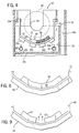
- Apparatus 110 is shown in FIGURE 12. Many of the same elements of other embodiments described herein (e.g. apparatus 10) are present in apparatus 110. However, apparatus 110 (shown without any baskets or associated elements) is adapted to plate cylinder 120 directly out of an electrolytic fluid a plating solution containing a plating metal or metal alloy in a plating solution indicated by reference letter F. According to this embodiment, cylinder 120 can be plated with any plating metal or metallic alloy. For example, cylinder 20a can be plated with chrome, zinc, nickel or other plating metal (including various alloys thereof) according to various processes known in the art.
- Apparatus 110 includes a plating tank 112 of a type shown in FIGURE 1 containing plating solution F at a level (indicated by reference letter L) regulated by the height of a weir 172.
- a rotogravure cylinder 120 to be plated (or deplated) is rotatably supported at its ends (e.g. upon an extending central shaft) to be submerged into the electrolytic fluid approximately one-half to one-third of the cylinder diameter.
- Cylinder 120 is rotatably supported at its ends by bearings within a journal, in which it is rotatably driven by a suitable powering device (not shown).
- Cylinder 120 shown in FIGURES 12 and 13 as one of a standard size (e.g., having a diameter of approximately 800 to 1500 mm); according to alternative embodiments cylinders of other diameters may be accommodated.
- the tank system and cylinder mounting and drive system are of a conventional arrangement known to those of ordinary skill in the art of rotogravure cylinder plating.
- the electrolytic fluid is itself of a composition known to those of ordinary skill in the art of electroplating.
- Conductive curved anode strips are electrically connected to current carrying rails 144 and mounted in plating tank to make electrical contact with the plating solution (electrolytic fluid F).
- the rails are connected to an anode side of a plating power supply (e.g. a current source of known design) and the cylinder is connected to a cathode side of the power supply; for de-plating, the anode-cathode connections are reversed.
- a plating power supply e.g. a current source of known design
- the cylinder is connected to a cathode side of the power supply; for de-plating, the anode-cathode connections are reversed.
- the cylinder is printed out (i.e. after having been plated and etched), it is returned to the plating apparatus and deplated so as to return the plating metal to the solution.
- other conventional arrangements for effecting the electrical connections to the plating solution (electrolytic fluid) and the cylinder may be employed.
- a mounting structure 143 (oriented similarly to the anode strips) is mounted to (but not electrically connected to) rails 144. (Or it alternatively can be mounted to the walls of plating tank 112.) Disposed lengthwise along the bottom surface of mounting structure 143 (e.g. bonded or securely mounted thereto) are ultrasonic transducer elements 150.
- Transducer elements 150 (shown as four elements 150a through 150d) are electrically coupled to a control system (shown schematically in FIGURE 10) and are provided to introduce ultrasonic wave energy into plating tank 112.
- Transducer elements 150 can be of a type disclosed herein or of any other suitable type known in the art.
- the transducer elements are designed to provide for operation in a frequency range of 15 to 30 KHz (cycles), although other ultrasonic frequency ranges (above 40 KHz and beyond) may be employed.
- Transducer elements 150 are configured and positioned to assist with the plating process (e.g. to facilitate consistency of ion migration through the electrolytic fluid), and to prevent any fouling buildup on the various elements of apparatus 110.
- the electrolytic fluid supply system functions as a closed circuit system.
- a supply of electrolytic fluid F is provided into plating tank 112 by at least one spray bar 162 (two are shown), which consists of a section of pipe or tube extending laterally along or near the bottom of plating tank 112.
- Each spray bar 162 has a series of apertures along its length (similar to as shown at least partially in FIGURE 2) that provide for a constant and relatively well-dispersed flow of electrolytic fluid into plating tank 112 from a holding tank 114 (e.g. a reservoir).
- a holding tank 114 is disposed beneath plating tank 112 so as to capture any flow of electrolytic fluid travelling over weir 172 in plating tank 112. (Electrolytic fluid F is maintained at its own level in holding tank 114.)
- Electrolytic fluid may build up heat and increase in temperature over time during the plating (or deplating) process and therefore holding tank 114 is equipped with a fluid cooling system 116 (e.g. a suitable heat exchanger for such fluid of a type known in the art). Likewise, electrolytic fluid may need to be heated from an ambient temperature to a higher temperature at the outset of the plating process and therefore holding tank 114 is also equipped with a fluid heating system 118 (e.g. a suitable heat exchanger for such fluid of a type known in the art).
- the temperature regulating system for the plating solution can be coupled to an automatic control system that operates from information obtained by temperature sensors in or near one or both tanks, and to control other parameters that may be monitored during the process, according to known arrangements.
- the ultrasonic system can be energized to provide for agitation of electrolytic fluid and for cleaning of the system to provide for better contact and plating performance.
- a pair of supply pipes 160 feed spray bars 162 with a supply flow of electrolytic fluid F.
- Supply pipes 160 each are coupled to a circulation pump 164 (configured and operated according to a known arrangement that may or may not have a filter).
- Circulation pumps 164 draw electrolytic fluid F from holding tank 114 into inlets in each of supply pipes 160 and force it under pressure into spray bars 162 where it is reintroduced through apertures into plating tank 112 for the electroplating process.
- Each of spray bars 162 extends along the bottom of plating tank 112, rising horizontally from holding tank 114 and turning at an elbow to run horizontally along and beneath mounting structure 143.
- the apparatus could include one pump coupled to either a single spray bar or a spray bar manifold system, or any other combination of elements that provide for the suitable supply of electrolytic fluid into the plating tank.
- FIGURE 13 An alternative embodiment is shown partially in FIGURE 13 (certain elements of the apparatus are not shown), wherein the apparatus 210 employs an ultrasonic transducer element 250 that is cylindrical in shape (having a diameter of about 70 mm in a particularly preferred embodiment).
- Transducer element 250 is shown mounted within plating tank 212 by a mounting structure 243 (for example, as mounting structure 143 shown in FIGURE 12).
- a mounting structure 243 integrated with the anode strips can be employed (compare FIGURE 3).
- one transducer element 250 is mounted underneath rotating cylinder 220 by mounting structure 243 (at or near the level of the curved anode strips below cylinder 220 according to the preferred embodiment).
- transducer elements can be used according to alternative embodiments, for example, mounted in a spaced-apart arrangement along the mounting structure beneath cylinder 220. Underneath transducer element 250 is placed a reflector 260 having a highly polished reflective surface shown mounted to side walls of plating tank 212.
- Reflector 260 is shown in the preferred embodiment as being of an integral unit having an arcuate shape, and extends substantially along the entire length of cylinder 220 (as does transducer element 250). Alternatively, the reflector can be provided with any other suitable shape (such as parabolic or flat or multi-faceted) or in segments.
- Transducer element 250 when energized will transmit wave energy (shown partially by reference letter U) in a substantially radial pattern through the plating solution, including toward cylinder 220 and against reflector 260 which will reflect the wave energy back to cylinder 220 and related structures (such as the anode strips).
- the direct and reflected ultrasonic wave energy is intended to keep the surfaces of the cylinder and related structures free of fouling buildup and to facilitate the plating process.
- ultrasonic wave energy can be used in the plating (and deplating) of various metals and metal alloys to the cylinder, as in chrome plating and also for plating alloys of zinc, nickel, etc.
- the ultrasonic system according any particularly preferred alternative embodiment will be capable of generating between two to six kilowatts of power; the system will provide ultrasonic energy at a frequency between 10 to 40 KHz (cycles per second).
- transducer elements e.g. cylindrical in shape with a circular profile
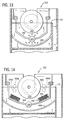
- four transducer elements 350a through 350d can be mounted in plating tank 312 at the sides of cylinder 220 (by a mounting structure fixed to the walls or base of the plating tank or some other suitable structure, not shown)
- two transducer elements e.g. 350b and 350d
- four transducer elements can be used instead of four.
- Transducer element 250 mounted by structure 243 and reflector 260 are also shown.
- transducer configurations can be made within the scope of the present invention, with any preferred embodiment including at least one transducer element positioned in or near the plating tank so that the beneficial effect of ultrasonic energy can be realized during the electroplating process.
- FIGURE 14 shows, such arrangements of transducer elements 350a through 350d (and 250) can also be employed in alternative embodiments used in connection with an electroplating apparatus that uses metal nuggets 334 maintained in basket compartments 332 (similar in arrangement to other embodiments described herein).
Landscapes
- Chemical & Material Sciences (AREA)
- Engineering & Computer Science (AREA)
- Chemical Kinetics & Catalysis (AREA)
- Electrochemistry (AREA)
- Materials Engineering (AREA)
- Metallurgy (AREA)
- Organic Chemistry (AREA)
- Crystallography & Structural Chemistry (AREA)
- Electroplating Methods And Accessories (AREA)
Applications Claiming Priority (2)
| Application Number | Priority Date | Filing Date | Title |
|---|---|---|---|
| US854879 | 1992-03-18 | ||
| US85487997A | 1997-05-12 | 1997-05-12 |
Publications (3)
| Publication Number | Publication Date |
|---|---|
| EP0884404A2 true EP0884404A2 (de) | 1998-12-16 |
| EP0884404A3 EP0884404A3 (de) | 1999-10-27 |
| EP0884404B1 EP0884404B1 (de) | 2004-02-25 |
Family
ID=25319766
Family Applications (1)
| Application Number | Title | Priority Date | Filing Date |
|---|---|---|---|
| EP97250241A Expired - Lifetime EP0884404B1 (de) | 1997-05-12 | 1997-08-18 | Vorrichtung zur Elektroplattierung eines Tiefdruckzylinders unter Verwendung von Ultraschallenergie |
Country Status (2)
| Country | Link |
|---|---|
| EP (1) | EP0884404B1 (de) |
| DE (2) | DE884404T1 (de) |
Cited By (3)
| Publication number | Priority date | Publication date | Assignee | Title |
|---|---|---|---|---|
| US6929723B2 (en) | 1996-11-22 | 2005-08-16 | Hubert F. Metzger | Electroplating apparatus using a non-dissolvable anode and ultrasonic energy |
| US7556722B2 (en) | 1996-11-22 | 2009-07-07 | Metzger Hubert F | Electroplating apparatus |
| US8298395B2 (en) | 1999-06-30 | 2012-10-30 | Chema Technology, Inc. | Electroplating apparatus |
Family Cites Families (4)
| Publication number | Priority date | Publication date | Assignee | Title |
|---|---|---|---|---|
| JPS5159729A (en) * | 1974-03-13 | 1976-05-25 | Mitsubishi Electric Corp | Denkimetsukiho oyobi sochi |
| US4352727A (en) * | 1980-12-01 | 1982-10-05 | Printing Machinery & Electronics Corporation, Inc. | Rotogravure cylinder plating and de-plating apparatus |
| US4647345A (en) * | 1986-06-05 | 1987-03-03 | Olin Corporation | Metallurgical structure control of electrodeposits using ultrasonic agitation |
| DE4113361A1 (de) * | 1990-04-26 | 1991-10-31 | Daetwyler Ag | Anlage zum galvanischen behandeln von drehkoerpern, insbesondere druckzylindern |
-
1997
- 1997-08-18 DE DE0884404T patent/DE884404T1/de active Pending
- 1997-08-18 EP EP97250241A patent/EP0884404B1/de not_active Expired - Lifetime
- 1997-08-18 DE DE69727791T patent/DE69727791T2/de not_active Expired - Lifetime
Cited By (5)
| Publication number | Priority date | Publication date | Assignee | Title |
|---|---|---|---|---|
| US6929723B2 (en) | 1996-11-22 | 2005-08-16 | Hubert F. Metzger | Electroplating apparatus using a non-dissolvable anode and ultrasonic energy |
| US7556722B2 (en) | 1996-11-22 | 2009-07-07 | Metzger Hubert F | Electroplating apparatus |
| US7914658B2 (en) | 1996-11-22 | 2011-03-29 | Chema Technology, Inc. | Electroplating apparatus |
| US8298395B2 (en) | 1999-06-30 | 2012-10-30 | Chema Technology, Inc. | Electroplating apparatus |
| US8758577B2 (en) | 1999-06-30 | 2014-06-24 | Chema Technology, Inc. | Electroplating apparatus |
Also Published As
| Publication number | Publication date |
|---|---|
| EP0884404A3 (de) | 1999-10-27 |
| DE69727791T2 (de) | 2004-08-05 |
| EP0884404B1 (de) | 2004-02-25 |
| DE884404T1 (de) | 1999-05-06 |
| DE69727791D1 (de) | 2004-04-01 |
Similar Documents
| Publication | Publication Date | Title |
|---|---|---|
| US8298395B2 (en) | Electroplating apparatus | |
| US7914658B2 (en) | Electroplating apparatus | |
| US5925231A (en) | Method for electroplating rotogravure cylinder using ultrasonic energy | |
| US6929723B2 (en) | Electroplating apparatus using a non-dissolvable anode and ultrasonic energy | |
| US4647345A (en) | Metallurgical structure control of electrodeposits using ultrasonic agitation | |
| AU2002346196B2 (en) | Vibratingly stirring apparatus, and device and method for processing using the stirring apparatus | |
| US4385967A (en) | Electroplating apparatus and method | |
| US6231728B1 (en) | Electroplating apparatus | |
| US4459183A (en) | Electroplating apparatus and method | |
| US4502933A (en) | Apparatus for electrolytic treatment to metal web | |
| US6547936B1 (en) | Electroplating apparatus having a non-dissolvable anode | |
| EP0884404B1 (de) | Vorrichtung zur Elektroplattierung eines Tiefdruckzylinders unter Verwendung von Ultraschallenergie | |
| US5348637A (en) | Surface treatment apparatus for workpieces | |
| US6197169B1 (en) | Apparatus and method for electroplating rotogravure cylinder using ultrasonic energy | |
| JP2707530B2 (ja) | めっき方法 | |
| JPS59190383A (ja) | 高速部分めつき方法およびその装置 | |
| KR100382177B1 (ko) | 양극 산화 처리 방법 및 장치 | |
| CN114182330B (zh) | 电镀装置 | |
| CN218880113U (zh) | 电镀装置 | |
| JP3995639B2 (ja) | 電解処理装置 | |
| CN223906959U (zh) | 一种改善钢丝质量的碱洗装置 | |
| CN223620529U (zh) | 一种钨丝表面处理用双超声波碱清洗装置 | |
| KR102958420B1 (ko) | 전기 도금 장치 | |
| US5478457A (en) | Apparatus for the continuous electrolytic treatment of wire-shaped objects | |
| JPH0665794A (ja) | アノード電極 |
Legal Events
| Date | Code | Title | Description |
|---|---|---|---|
| PUAI | Public reference made under article 153(3) epc to a published international application that has entered the european phase |
Free format text: ORIGINAL CODE: 0009012 |
|
| AK | Designated contracting states |
Kind code of ref document: A2 Designated state(s): CH DE ES IT LI |
|
| DET | De: translation of patent claims | ||
| PUAL | Search report despatched |
Free format text: ORIGINAL CODE: 0009013 |
|
| AK | Designated contracting states |
Kind code of ref document: A3 Designated state(s): AT BE CH DE DK ES FI FR GB GR IE IT LI LU MC NL PT SE |
|
| 17P | Request for examination filed |
Effective date: 20000407 |
|
| AKX | Designation fees paid |
Free format text: CH DE ES IT LI |
|
| 17Q | First examination report despatched |
Effective date: 20020806 |
|
| GRAH | Despatch of communication of intention to grant a patent |
Free format text: ORIGINAL CODE: EPIDOS IGRA |
|
| GRAS | Grant fee paid |
Free format text: ORIGINAL CODE: EPIDOSNIGR3 |
|
| GRAA | (expected) grant |
Free format text: ORIGINAL CODE: 0009210 |
|
| AK | Designated contracting states |
Kind code of ref document: B1 Designated state(s): CH DE ES IT LI |
|
| REG | Reference to a national code |
Ref country code: CH Ref legal event code: EP |
|
| REF | Corresponds to: |
Ref document number: 69727791 Country of ref document: DE Date of ref document: 20040401 Kind code of ref document: P |
|
| REG | Reference to a national code |
Ref country code: CH Ref legal event code: NV Representative=s name: R. A. EGLI & CO. PATENTANWAELTE |
|
| PG25 | Lapsed in a contracting state [announced via postgrant information from national office to epo] |
Ref country code: ES Free format text: LAPSE BECAUSE OF FAILURE TO SUBMIT A TRANSLATION OF THE DESCRIPTION OR TO PAY THE FEE WITHIN THE PRESCRIBED TIME-LIMIT Effective date: 20040605 |
|
| PLBE | No opposition filed within time limit |
Free format text: ORIGINAL CODE: 0009261 |
|
| STAA | Information on the status of an ep patent application or granted ep patent |
Free format text: STATUS: NO OPPOSITION FILED WITHIN TIME LIMIT |
|
| 26N | No opposition filed |
Effective date: 20041126 |
|
| PGFP | Annual fee paid to national office [announced via postgrant information from national office to epo] |
Ref country code: CH Payment date: 20090825 Year of fee payment: 13 |
|
| PGFP | Annual fee paid to national office [announced via postgrant information from national office to epo] |
Ref country code: IT Payment date: 20090821 Year of fee payment: 13 |
|
| REG | Reference to a national code |
Ref country code: CH Ref legal event code: PL |
|
| PG25 | Lapsed in a contracting state [announced via postgrant information from national office to epo] |
Ref country code: LI Free format text: LAPSE BECAUSE OF NON-PAYMENT OF DUE FEES Effective date: 20100831 Ref country code: CH Free format text: LAPSE BECAUSE OF NON-PAYMENT OF DUE FEES Effective date: 20100831 |
|
| PG25 | Lapsed in a contracting state [announced via postgrant information from national office to epo] |
Ref country code: IT Free format text: LAPSE BECAUSE OF NON-PAYMENT OF DUE FEES Effective date: 20100818 |
|
| PGFP | Annual fee paid to national office [announced via postgrant information from national office to epo] |
Ref country code: DE Payment date: 20160822 Year of fee payment: 20 |
|
| REG | Reference to a national code |
Ref country code: DE Ref legal event code: R071 Ref document number: 69727791 Country of ref document: DE |