EP0884411A1 - Schusseintragsvorrichtung für Greiferwebmaschinen und dreidimensionaler Kurbelmechanismus dafür - Google Patents
Schusseintragsvorrichtung für Greiferwebmaschinen und dreidimensionaler Kurbelmechanismus dafür Download PDFInfo
- Publication number
- EP0884411A1 EP0884411A1 EP98110420A EP98110420A EP0884411A1 EP 0884411 A1 EP0884411 A1 EP 0884411A1 EP 98110420 A EP98110420 A EP 98110420A EP 98110420 A EP98110420 A EP 98110420A EP 0884411 A1 EP0884411 A1 EP 0884411A1
- Authority
- EP
- European Patent Office
- Prior art keywords
- shaft
- dimensional
- inserting apparatus
- crank mechanism
- driven gear
- Prior art date
- Legal status (The legal status is an assumption and is not a legal conclusion. Google has not performed a legal analysis and makes no representation as to the accuracy of the status listed.)
- Granted
Links
- 230000007246 mechanism Effects 0.000 title claims abstract description 44
- 230000033001 locomotion Effects 0.000 claims description 9
- 238000003780 insertion Methods 0.000 abstract description 7
- 230000037431 insertion Effects 0.000 abstract description 5
- 230000008878 coupling Effects 0.000 description 5
- 238000010168 coupling process Methods 0.000 description 5
- 238000005859 coupling reaction Methods 0.000 description 5
- 238000000034 method Methods 0.000 description 4
- 230000008569 process Effects 0.000 description 4
- 230000000694 effects Effects 0.000 description 2
- 238000012986 modification Methods 0.000 description 2
- 230000004048 modification Effects 0.000 description 2
- 230000003014 reinforcing effect Effects 0.000 description 2
- 239000002759 woven fabric Substances 0.000 description 2
- 235000014676 Phragmites communis Nutrition 0.000 description 1
- 230000009471 action Effects 0.000 description 1
- 230000005540 biological transmission Effects 0.000 description 1
- 239000000470 constituent Substances 0.000 description 1
- 238000010276 construction Methods 0.000 description 1
- 230000002708 enhancing effect Effects 0.000 description 1
- 230000002093 peripheral effect Effects 0.000 description 1
Images


Classifications
-
- D—TEXTILES; PAPER
- D03—WEAVING
- D03D—WOVEN FABRICS; METHODS OF WEAVING; LOOMS
- D03D47/00—Looms in which bulk supply of weft does not pass through shed, e.g. shuttleless looms, gripper shuttle looms, dummy shuttle looms
- D03D47/27—Drive or guide mechanisms for weft inserting
- D03D47/271—Rapiers
- D03D47/272—Rapier bands
-
- D—TEXTILES; PAPER
- D03—WEAVING
- D03D—WOVEN FABRICS; METHODS OF WEAVING; LOOMS
- D03D47/00—Looms in which bulk supply of weft does not pass through shed, e.g. shuttleless looms, gripper shuttle looms, dummy shuttle looms
- D03D47/27—Drive or guide mechanisms for weft inserting
- D03D47/275—Drive mechanisms
Definitions
- the present invention relates generally to a weft inserting apparatus for a rapier loom. More particularly, the invention is concerned with a weft inserting apparatus equipped with three-dimensional crank mechanisms for reciprocatively moving (i.e., feeding and retracting) rapier heads for inserting a weft into a shedding formed or defined by warps in a rapier loom.
- a three-dimensional crank mechanism for converting or translating a rotation in a given direction into a reciprocative movement or motion has heretofore been known, as is disclosed, for instance, in Japanese Patent Laid-open Nos. JP-A-64-68544 and JP-A-7-324253.
- a circular collar is fit on a disk of a hemispherical coupling joint fixedly mounted on a main shaft, wherein a fork is supported on the collar by means of a pin.
- the collar is made to swing accompaniment with the rotation of the coupling joint in one direction, and the swinging motion of the collar is converted or translated into reciprocating motion of the fork by way of the pin.
- an intermediate bifurcated link is rotatably supported on an oblique shaft crank portion secured to an end of a drive shaft, wherein a supporting shaft is rotatably supported between end tips of the intermediate bifurcated link.
- a segment gear is fixedly mounted on the supporting shaft at an intermediate portion thereof.
- a weft inserting apparatus for a rapier loom in which a balancing weight is provided in each three-dimensional crank mechanism to improve the rotational balance of the drive shaft of each three-dimensional crank mechanism. It has been found that the provision of such balancing weight is very effective in enhancing the rotational balance (or balanced rotation) of the three-dimensional crank mechanism.
- each of the balancing weights may be provided at the side opposite to the location at which an oblique shaft crank portion is mounted in each of the three-dimensional crank mechanisms with the drive shaft being interposed between the balancing weight and the oblique shaft crank portion. So far as the above condition is satisfied, the position at which the balancing weight is provided along the axial direction of the drive shaft is not limited.
- the drive shaft is provided with a driven gear for transmission of a driving force, wherein the oblique shaft crank portion of the three-dimensional crank mechanism is formed integrally on a lateral or side surface of the driven gear. Owing to this arrangement, the process for assembling the three-dimensional crank mechanism can be greatly simplified.
- the balancing weight may be formed integrally on the lateral or side surface of the driven gear in diametrical opposition to the oblique shaft crank portion with the drive shaft being interposed therebetween. This arrangement can equally contribute to simplification of the process of assembling the three-dimensional crank mechanism.
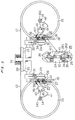
- reference numeral 11 denotes a weft feeding rapier head which is adapted to be inserted into a shedding formed by warps (not shown) from a weft-insertion starting side.
- the weft feeding rapier head 11 is secured to a rapier band 12 at a leading end thereof.
- the rapier band 12 is wound around a rapier wheel 13 and secured thereto at the other end.
- the rapier wheel 13 is mounted on a shaft 14 to be reciprocatively rotatable about the shaft 14.
- the weft feeding rapier head inserted into the shedding, as shown in Fig. 3, whereupon the feeding rapier head 11 is retracted from the shedding with the rapier wheel 13 being rotated backward (counterclockwise in the figure), as can be seen in Fig. 2.
- a rapier wheel 15 is disposed at a weft insertion terminal side so as to be reciprocatively rotatable around a shaft 16.
- a weft receiving rapier head 18 is secured to a rapier band 17 at a leading end thereof.
- the rapier band 17 is wound around the rapier wheel 15 and coupled thereto at the other end.
- Both of the rapier heads 11 and 18 are adapted to run or travel on and along a sley 20 which serves to support a reed 19.
- the sley 20 is supported on a rocking shaft 22 by means of sley swords 21.
- the sley 20 is integrally rotated with the rocking shaft 22 around a center axis thereof.
- Disposed rotatably immediately beneath the rocking shaft 22 are drive shafts 23 and 24 which extend in parallel to the rocking shaft 22 (see Figs. 2 and 3).
- the drive shafts 23 and 24 are supported on supporting walls 35 and 36 by means of bearing members 33 and 34, respectively, (see Fig. 2, partially enlarged view encircled by a broken line).
- Double cams 29 and 30 are fixedly mounted on the drive shafts 23 and 24 at inner sides relative to the supporting walls 35 and 36, respectively, while double cam levers 31 and 32 are fixedly mounted on the rocking shaft 22 at both end portions thereof, respectively. Rotation of the drive shafts 23 and 24 in one direction is translated into reciprocating swing motion of the rocking shaft 22 through the medium of the double cams 29 and 30 and the double cam levers 31 and 32, respectively.
- Each of the drive gears 27 and 28 is operatively connected to a loom driving motor (not shown) and adapted to rotate in only one direction.
- the driven gears 25 and 26 have respective lateral or side surfaces on which oblique shaft crank portions 37 and 38 are integrally formed, respectively, while reinforcing flanges 251 and 261 are formed integrally with peripheral edges of the driven gears 25 and 26, respectively.
- Each of the oblique shaft crank portions 37 and 38 is so formed as to extend in the radial direction from the rotational center (center axis) of the driven gear 25 or 26 to the respective reinforcing flange 251 or 261 , wherein bifurcated intermediate links 39 and 40 are revolvably supported on the oblique shaft crank portions 37 and 38 by means of bearing members 41 and 42, respectively.
- the bifurcated intermediate links 39 and 40 have respective base shafts 391 and 401 disposed obliquely relative to the center axes of the driven gears 25 and 26, respectively.
- balancing weights 252 and 262 Integrally formed on the lateral or side surfaces of the driven gears 25 and 26 are balancing weights 252 and 262, respectively, which are disposed opposite the oblique shaft crank portions 37 and 38, respectively, with the rotational centers (or center axes) of the drive shafts 23 and 24 being interposed therebetween, respectively.
- the rotational momentum of the balancing weight 252;262 is so selected as to substantially coincide with that of the oblique shaft crank portion 37;38 around the drive shaft 23;24.
- rocking shafts 43 and 44 Supported swingably on the bifurcated intermediate links 39 and 40 between the tip ends thereof are rocking shafts 43 and 44, respectively, wherein supporting shafts 45 and 46 extending orthogonically to each other are mounted fixedly on the rocking shafts 43 and 44 at intermediate or center portions thereof, respectively.
- Segment gears 47 and 48 are swingably supported on the supporting shafts 45 and 46, respectively.
- the drive shaft 23, the driven gear 25, the bifurcated intermediate link 39, the rocking shaft 43 and the segment gear 47 cooperate to constitute the three-dimensional crank mechanism 49 for the weft feeding rapier head 11, while the drive shaft 24, the driven gear 26, the bifurcated intermediate link 40, the rocking shaft 44 and the segment gear 48 constitute the three-dimensional crank mechanism 50 for the weft receiving rapier head 18.
- the segment gears 47 and 48 are adapted to mesh with driven gears 141 and 161 secured to the shafts 14 and 16, respectively.
- Rotation of the drive shaft 23 in one direction is translated into reciprocative rotational motion of the rapier wheel 13 through the three-dimensional crank mechanism 49 and the driven gear 141, while rotation of the drive shaft 24 in one direction is translated into reciprocative rotational motion of the rapier wheel 15 through the three-dimensional crank mechanism 50 and the driven gear 161.
- the three-dimensional crank mechanisms 49 and 50 are arranged symmetrically to each other so that the rapier wheels 13 and 15 can rotate in opposite directions, respectively.
- both the rapier heads 11 and 18 are made to travel into the shedding in synchronization with each other so that they encounter each other at a central location as viewed in the widthwise direction of the woven fabric, which is then followed by retraction of the rapier heads 11 and 18 in opposite directions, respectively.
- the weft (not shown) transported into the shedding by the feeding rapier head 11 is transferred to the receiving rapier head 18.
- the receiving rapier head 18 Upon retraction of the receiving rapier head 18 from the shedding, and the weft is thereby inserted completely through the shedding formed by the warps.
- the weft inserting apparatus according to the first embodiment of the invention enjoys advantageous effects which will be mentioned below.
- FIG. 4 description will be made of the weft inserting apparatus according to a second embodiment of the invention.
- components that are the same as or equivalent to those of the weft inserting apparatus according to the first embodiment are denoted by like reference characters.
- the three-dimensional crank mechanisms provided at both sides of the rapier loom are arranged with the same symmetrical structure relative to the longitudinal axis of the loom, the following description will be directed to the structure relating to the weft feeding rapier head 11, with the understanding that the following description holds equally true for the structure associated with the weft receiving rapier band 12.
- the driven gear 51 and the oblique shaft crank portion 52 are formed separately, whereas a balancing weight 521 is formed integrally with the oblique shaft crank portion 52. More specifically, the balancing weight 521 and the oblique shaft crank portion 52 are formed substantially symmetrical to each other with reference to the center axis of the drive shaft 23 interposed therebetween so that the rotational momentum of the oblique shaft crank portion 52 around the drive shaft 23 generally coincides with that of the balancing weight 521. By virtue of this arrangement, the rotational balance of the three-dimensional crank mechanism 49 can be improved.
- the balancing weight 521 may be so dimensioned that the rotational momentum thereof around the drive shaft 23 substantially coincides with that of the oblique shaft crank portion 52 and the bifurcated intermediate link 39. Further, the thickness of one cam constituting the double cam 29 may be increased to thereby act as the balancing weight.
- the teachings of the present invention can be applied to the three-dimensional crank mechanism disclosed in Japanese Patent Laid-open No. JP-A-64-68544 as described in the Description of Related Art.
- the coupling joint may be so shaped as to be rotationally symmetrical relative to the axis of the main shaft. Accordingly, all suitable modifications and equivalents may be resorted to, falling within the spirit and scope of the invention.
Landscapes
- Engineering & Computer Science (AREA)
- Textile Engineering (AREA)
- Looms (AREA)
Applications Claiming Priority (2)
| Application Number | Priority Date | Filing Date | Title |
|---|---|---|---|
| JP9153994A JPH111845A (ja) | 1997-06-11 | 1997-06-11 | レピア織機における緯入れ装置 |
| JP153944/97 | 1997-06-11 |
Publications (2)
| Publication Number | Publication Date |
|---|---|
| EP0884411A1 true EP0884411A1 (de) | 1998-12-16 |
| EP0884411B1 EP0884411B1 (de) | 2006-08-23 |
Family
ID=15574601
Family Applications (1)
| Application Number | Title | Priority Date | Filing Date |
|---|---|---|---|
| EP98110420A Expired - Lifetime EP0884411B1 (de) | 1997-06-11 | 1998-06-08 | Schusseintragsvorrichtung für Greiferwebmaschinen und dreidimensionaler Kurbelmechanismus dafür |
Country Status (2)
| Country | Link |
|---|---|
| EP (1) | EP0884411B1 (de) |
| JP (1) | JPH111845A (de) |
Cited By (6)
| Publication number | Priority date | Publication date | Assignee | Title |
|---|---|---|---|---|
| CN1103251C (zh) * | 1998-12-15 | 2003-03-19 | 卡尔玛有限公司 | 扳机致动的抽吸喷射器 |
| EP1903133A1 (de) * | 2006-09-22 | 2008-03-26 | SCHÖNHERR Textilmaschinenbau GmbH | Vorrichtung zur Betätigung eines flexiblen Webschützen und Webmaschine, die mindestens eine solche Vorrichtung integriert |
| CN101696528B (zh) * | 2009-10-22 | 2011-05-25 | 浙江理工大学 | 非圆齿轮行星轮系打纬机构 |
| CN102644146A (zh) * | 2012-04-16 | 2012-08-22 | 经纬纺织机械股份有限公司 | 剑杆织机球面曲柄摇杆装配定位装置 |
| CN102926103A (zh) * | 2011-08-09 | 2013-02-13 | 王志坚 | 剑杆织机的曲柄摇杆引纬机构 |
| CN105714454A (zh) * | 2016-03-23 | 2016-06-29 | 浙江万利纺织机械有限公司 | 一种带有静平衡结构的剑杆织机主轴组件及初始相位的定位方法 |
Families Citing this family (2)
| Publication number | Priority date | Publication date | Assignee | Title |
|---|---|---|---|---|
| KR101057802B1 (ko) | 2009-05-01 | 2011-08-19 | 주식회사세일정밀 | 제트직기의 위사 위입장치 |
| CN101603232B (zh) * | 2009-05-14 | 2011-01-26 | 经纬纺织机械股份有限公司 | 剑杆织机非圆齿轮引纬装置 |
Citations (4)
| Publication number | Priority date | Publication date | Assignee | Title |
|---|---|---|---|---|
| FR2463215A1 (fr) * | 1979-08-06 | 1981-02-20 | Rueti Ag Maschf | Dispositif d'entrainement pour la roue de ruban d'un metier a tisser a griffes |
| US4784005A (en) * | 1986-10-18 | 1988-11-15 | Lindauer Dornier Gesellschaft Mbh | Crank drive having four spacially extending axes intersecting in one point |
| JPH07324253A (ja) * | 1994-05-27 | 1995-12-12 | Toyota Autom Loom Works Ltd | レピア織機における緯入れ装置及び筬打ち装置 |
| EP0726341A2 (de) * | 1995-02-08 | 1996-08-14 | Kabushiki Kaisha Toyoda Jidoshokki Seisakusho | Vorrichtung für den Schusseintrag in einer Bandgreiferwebmaschine |
-
1997
- 1997-06-11 JP JP9153994A patent/JPH111845A/ja active Pending
-
1998
- 1998-06-08 EP EP98110420A patent/EP0884411B1/de not_active Expired - Lifetime
Patent Citations (4)
| Publication number | Priority date | Publication date | Assignee | Title |
|---|---|---|---|---|
| FR2463215A1 (fr) * | 1979-08-06 | 1981-02-20 | Rueti Ag Maschf | Dispositif d'entrainement pour la roue de ruban d'un metier a tisser a griffes |
| US4784005A (en) * | 1986-10-18 | 1988-11-15 | Lindauer Dornier Gesellschaft Mbh | Crank drive having four spacially extending axes intersecting in one point |
| JPH07324253A (ja) * | 1994-05-27 | 1995-12-12 | Toyota Autom Loom Works Ltd | レピア織機における緯入れ装置及び筬打ち装置 |
| EP0726341A2 (de) * | 1995-02-08 | 1996-08-14 | Kabushiki Kaisha Toyoda Jidoshokki Seisakusho | Vorrichtung für den Schusseintrag in einer Bandgreiferwebmaschine |
Non-Patent Citations (1)
| Title |
|---|
| PATENT ABSTRACTS OF JAPAN vol. 096, no. 004 30 April 1996 (1996-04-30) * |
Cited By (9)
| Publication number | Priority date | Publication date | Assignee | Title |
|---|---|---|---|---|
| CN1103251C (zh) * | 1998-12-15 | 2003-03-19 | 卡尔玛有限公司 | 扳机致动的抽吸喷射器 |
| EP1903133A1 (de) * | 2006-09-22 | 2008-03-26 | SCHÖNHERR Textilmaschinenbau GmbH | Vorrichtung zur Betätigung eines flexiblen Webschützen und Webmaschine, die mindestens eine solche Vorrichtung integriert |
| FR2906266A1 (fr) * | 2006-09-22 | 2008-03-28 | Schonherr Textilmaschb Gmbh | Dispositif de commande de lance flexible et metier a tisser incorporant au moins un tel dispositif |
| CN101696528B (zh) * | 2009-10-22 | 2011-05-25 | 浙江理工大学 | 非圆齿轮行星轮系打纬机构 |
| CN102926103A (zh) * | 2011-08-09 | 2013-02-13 | 王志坚 | 剑杆织机的曲柄摇杆引纬机构 |
| CN102644146A (zh) * | 2012-04-16 | 2012-08-22 | 经纬纺织机械股份有限公司 | 剑杆织机球面曲柄摇杆装配定位装置 |
| CN102644146B (zh) * | 2012-04-16 | 2013-08-14 | 经纬纺织机械股份有限公司 | 剑杆织机球面曲柄摇杆装配定位装置 |
| CN105714454A (zh) * | 2016-03-23 | 2016-06-29 | 浙江万利纺织机械有限公司 | 一种带有静平衡结构的剑杆织机主轴组件及初始相位的定位方法 |
| CN105714454B (zh) * | 2016-03-23 | 2017-08-04 | 浙江万利纺织机械有限公司 | 一种带有静平衡结构的剑杆织机主轴组件及初始相位的定位方法 |
Also Published As
| Publication number | Publication date |
|---|---|
| EP0884411B1 (de) | 2006-08-23 |
| JPH111845A (ja) | 1999-01-06 |
Similar Documents
| Publication | Publication Date | Title |
|---|---|---|
| EP0884411B1 (de) | Schusseintragsvorrichtung für Greiferwebmaschinen und dreidimensionaler Kurbelmechanismus dafür | |
| US8109809B2 (en) | Eccentric transmission with an imbalance | |
| JPS6058868B2 (ja) | レバ−操作式車椅子 | |
| KR20230049728A (ko) | 스크롤 압축기용 보정 메커니즘 | |
| US6012346A (en) | Low vibration motion translation system | |
| JPH09242559A (ja) | 往復ピストン機械、特に内燃機関のための内サイクロイド式クランク装置 | |
| CN109853336A (zh) | 一种耐冲击的压路机钢轮激振结构 | |
| JPH09224349A (ja) | モータ装置 | |
| EP0627571A1 (de) | Schwingungsdämpfer für eine Membrankupplung | |
| RU2454312C2 (ru) | Ручная машина с ударным механизмом | |
| JP3550940B2 (ja) | 流体機械 | |
| US6334423B1 (en) | Reciprocating piston engine and its link mechanism | |
| JPH06317263A (ja) | スクロール圧縮機 | |
| US3784319A (en) | Coriolis-relieving aircraft rotor assembly | |
| EP1600540B1 (de) | Webladenvorrichtung für Webmaschine | |
| JP2716500B2 (ja) | 自動車の窓ガラス用ワイパ装置 | |
| US12510079B2 (en) | Compensation mechanism for a displacement machine | |
| JP3426113B2 (ja) | 往復動ピストン機構 | |
| CN212085936U (zh) | 一种低振动三相异步电动机 | |
| JPH11343801A (ja) | 往復動ピストン機関及びリンク機構 | |
| RU2011073C1 (ru) | Эксцентриковый привод | |
| CN217736015U (zh) | 曲轴及具备其的发动机 | |
| CN111721532B (zh) | 一种长杆类杆端关节轴承内外圈同步转动试验机 | |
| JP4271653B2 (ja) | ギヤ切替フォーク | |
| KR200160775Y1 (ko) | 크랭크 샤프트 기어의 연결 구조 |
Legal Events
| Date | Code | Title | Description |
|---|---|---|---|
| PUAI | Public reference made under article 153(3) epc to a published international application that has entered the european phase |
Free format text: ORIGINAL CODE: 0009012 |
|
| AK | Designated contracting states |
Kind code of ref document: A1 Designated state(s): BE CH IT LI |
|
| AX | Request for extension of the european patent |
Free format text: AL;LT;LV;MK;RO;SI |
|
| K1C1 | Correction of patent application (title page) published |
Effective date: 19981216 |
|
| 17P | Request for examination filed |
Effective date: 19990520 |
|
| AKX | Designation fees paid |
Free format text: BE CH IT LI |
|
| REG | Reference to a national code |
Ref country code: DE Ref legal event code: 8566 |
|
| RAP1 | Party data changed (applicant data changed or rights of an application transferred) |
Owner name: KABUSHIKI KAISHA TOYOTA JIDOSHOKKI |
|
| 17Q | First examination report despatched |
Effective date: 20011214 |
|
| GRAP | Despatch of communication of intention to grant a patent |
Free format text: ORIGINAL CODE: EPIDOSNIGR1 |
|
| GRAS | Grant fee paid |
Free format text: ORIGINAL CODE: EPIDOSNIGR3 |
|
| GRAA | (expected) grant |
Free format text: ORIGINAL CODE: 0009210 |
|
| AK | Designated contracting states |
Kind code of ref document: B1 Designated state(s): BE CH IT LI |
|
| PG25 | Lapsed in a contracting state [announced via postgrant information from national office to epo] |
Ref country code: IT Free format text: LAPSE BECAUSE OF FAILURE TO SUBMIT A TRANSLATION OF THE DESCRIPTION OR TO PAY THE FEE WITHIN THE PRESCRIBED TIME-LIMIT;WARNING: LAPSES OF ITALIAN PATENTS WITH EFFECTIVE DATE BEFORE 2007 MAY HAVE OCCURRED AT ANY TIME BEFORE 2007. THE CORRECT EFFECTIVE DATE MAY BE DIFFERENT FROM THE ONE RECORDED. Effective date: 20060823 |
|
| REG | Reference to a national code |
Ref country code: CH Ref legal event code: EP |
|
| REG | Reference to a national code |
Ref country code: CH Ref legal event code: NV Representative=s name: NOVAGRAAF INTERNATIONAL SA |
|
| PGFP | Annual fee paid to national office [announced via postgrant information from national office to epo] |
Ref country code: BE Payment date: 20070531 Year of fee payment: 10 |
|
| PGFP | Annual fee paid to national office [announced via postgrant information from national office to epo] |
Ref country code: CH Payment date: 20070608 Year of fee payment: 10 |
|
| PLBE | No opposition filed within time limit |
Free format text: ORIGINAL CODE: 0009261 |
|
| STAA | Information on the status of an ep patent application or granted ep patent |
Free format text: STATUS: NO OPPOSITION FILED WITHIN TIME LIMIT |
|
| 26N | No opposition filed |
Effective date: 20070524 |
|
| PGFP | Annual fee paid to national office [announced via postgrant information from national office to epo] |
Ref country code: IT Payment date: 20070625 Year of fee payment: 10 |
|
| BERE | Be: lapsed |
Owner name: K.K. *TOYOTA JIDOSHOKKI Effective date: 20080630 |
|
| REG | Reference to a national code |
Ref country code: CH Ref legal event code: PL |
|
| PG25 | Lapsed in a contracting state [announced via postgrant information from national office to epo] |
Ref country code: BE Free format text: LAPSE BECAUSE OF NON-PAYMENT OF DUE FEES Effective date: 20080630 |
|
| PG25 | Lapsed in a contracting state [announced via postgrant information from national office to epo] |
Ref country code: LI Free format text: LAPSE BECAUSE OF NON-PAYMENT OF DUE FEES Effective date: 20080630 Ref country code: CH Free format text: LAPSE BECAUSE OF NON-PAYMENT OF DUE FEES Effective date: 20080630 |
|
| PG25 | Lapsed in a contracting state [announced via postgrant information from national office to epo] |
Ref country code: IT Free format text: LAPSE BECAUSE OF NON-PAYMENT OF DUE FEES Effective date: 20080608 |