EP0884459A2 - Überzogene Katalysatorträger und Halterungen - Google Patents
Überzogene Katalysatorträger und Halterungen Download PDFInfo
- Publication number
- EP0884459A2 EP0884459A2 EP98109695A EP98109695A EP0884459A2 EP 0884459 A2 EP0884459 A2 EP 0884459A2 EP 98109695 A EP98109695 A EP 98109695A EP 98109695 A EP98109695 A EP 98109695A EP 0884459 A2 EP0884459 A2 EP 0884459A2
- Authority
- EP
- European Patent Office
- Prior art keywords
- ceramic
- coating
- mat
- accordance
- honeycomb body
- Prior art date
- Legal status (The legal status is an assumption and is not a legal conclusion. Google has not performed a legal analysis and makes no representation as to the accuracy of the status listed.)
- Withdrawn
Links
Images

Classifications
-
- F—MECHANICAL ENGINEERING; LIGHTING; HEATING; WEAPONS; BLASTING
- F01—MACHINES OR ENGINES IN GENERAL; ENGINE PLANTS IN GENERAL; STEAM ENGINES
- F01N—GAS-FLOW SILENCERS OR EXHAUST APPARATUS FOR MACHINES OR ENGINES IN GENERAL; GAS-FLOW SILENCERS OR EXHAUST APPARATUS FOR INTERNAL-COMBUSTION ENGINES
- F01N13/00—Exhaust or silencing apparatus characterised by constructional features
- F01N13/14—Exhaust or silencing apparatus characterised by constructional features having thermal insulation
-
- B—PERFORMING OPERATIONS; TRANSPORTING
- B01—PHYSICAL OR CHEMICAL PROCESSES OR APPARATUS IN GENERAL
- B01J—CHEMICAL OR PHYSICAL PROCESSES, e.g. CATALYSIS OR COLLOID CHEMISTRY; THEIR RELEVANT APPARATUS
- B01J19/00—Chemical, physical or physico-chemical processes in general; Their relevant apparatus
- B01J19/02—Apparatus characterised by being constructed of material selected for its chemically-resistant properties
-
- B—PERFORMING OPERATIONS; TRANSPORTING
- B01—PHYSICAL OR CHEMICAL PROCESSES OR APPARATUS IN GENERAL
- B01J—CHEMICAL OR PHYSICAL PROCESSES, e.g. CATALYSIS OR COLLOID CHEMISTRY; THEIR RELEVANT APPARATUS
- B01J19/00—Chemical, physical or physico-chemical processes in general; Their relevant apparatus
- B01J19/24—Stationary reactors without moving elements inside
- B01J19/248—Reactors comprising multiple separated flow channels
- B01J19/2485—Monolithic reactors
-
- B—PERFORMING OPERATIONS; TRANSPORTING
- B01—PHYSICAL OR CHEMICAL PROCESSES OR APPARATUS IN GENERAL
- B01J—CHEMICAL OR PHYSICAL PROCESSES, e.g. CATALYSIS OR COLLOID CHEMISTRY; THEIR RELEVANT APPARATUS
- B01J37/00—Processes, in general, for preparing catalysts; Processes, in general, for activation of catalysts
- B01J37/02—Impregnation, coating or precipitation
- B01J37/024—Multiple impregnation or coating
- B01J37/0244—Coatings comprising several layers
-
- F—MECHANICAL ENGINEERING; LIGHTING; HEATING; WEAPONS; BLASTING
- F01—MACHINES OR ENGINES IN GENERAL; ENGINE PLANTS IN GENERAL; STEAM ENGINES
- F01N—GAS-FLOW SILENCERS OR EXHAUST APPARATUS FOR MACHINES OR ENGINES IN GENERAL; GAS-FLOW SILENCERS OR EXHAUST APPARATUS FOR INTERNAL-COMBUSTION ENGINES
- F01N3/00—Exhaust or silencing apparatus having means for purifying, rendering innocuous, or otherwise treating exhaust
- F01N3/08—Exhaust or silencing apparatus having means for purifying, rendering innocuous, or otherwise treating exhaust for rendering innocuous
- F01N3/10—Exhaust or silencing apparatus having means for purifying, rendering innocuous, or otherwise treating exhaust for rendering innocuous by thermal or catalytic conversion of noxious components of exhaust
- F01N3/24—Exhaust or silencing apparatus having means for purifying, rendering innocuous, or otherwise treating exhaust for rendering innocuous by thermal or catalytic conversion of noxious components of exhaust characterised by constructional aspects of converting apparatus
- F01N3/28—Construction of catalytic reactors
- F01N3/2803—Construction of catalytic reactors characterised by structure, by material or by manufacturing of catalyst support
- F01N3/2825—Ceramics
- F01N3/2828—Ceramic multi-channel monoliths, e.g. honeycombs
-
- F—MECHANICAL ENGINEERING; LIGHTING; HEATING; WEAPONS; BLASTING
- F01—MACHINES OR ENGINES IN GENERAL; ENGINE PLANTS IN GENERAL; STEAM ENGINES
- F01N—GAS-FLOW SILENCERS OR EXHAUST APPARATUS FOR MACHINES OR ENGINES IN GENERAL; GAS-FLOW SILENCERS OR EXHAUST APPARATUS FOR INTERNAL-COMBUSTION ENGINES
- F01N3/00—Exhaust or silencing apparatus having means for purifying, rendering innocuous, or otherwise treating exhaust
- F01N3/08—Exhaust or silencing apparatus having means for purifying, rendering innocuous, or otherwise treating exhaust for rendering innocuous
- F01N3/10—Exhaust or silencing apparatus having means for purifying, rendering innocuous, or otherwise treating exhaust for rendering innocuous by thermal or catalytic conversion of noxious components of exhaust
- F01N3/24—Exhaust or silencing apparatus having means for purifying, rendering innocuous, or otherwise treating exhaust for rendering innocuous by thermal or catalytic conversion of noxious components of exhaust characterised by constructional aspects of converting apparatus
- F01N3/28—Construction of catalytic reactors
- F01N3/2839—Arrangements for mounting catalyst support in housing, e.g. with means for compensating thermal expansion or vibration
- F01N3/2853—Arrangements for mounting catalyst support in housing, e.g. with means for compensating thermal expansion or vibration using mats or gaskets between catalyst body and housing
-
- F—MECHANICAL ENGINEERING; LIGHTING; HEATING; WEAPONS; BLASTING
- F01—MACHINES OR ENGINES IN GENERAL; ENGINE PLANTS IN GENERAL; STEAM ENGINES
- F01N—GAS-FLOW SILENCERS OR EXHAUST APPARATUS FOR MACHINES OR ENGINES IN GENERAL; GAS-FLOW SILENCERS OR EXHAUST APPARATUS FOR INTERNAL-COMBUSTION ENGINES
- F01N3/00—Exhaust or silencing apparatus having means for purifying, rendering innocuous, or otherwise treating exhaust
- F01N3/08—Exhaust or silencing apparatus having means for purifying, rendering innocuous, or otherwise treating exhaust for rendering innocuous
- F01N3/10—Exhaust or silencing apparatus having means for purifying, rendering innocuous, or otherwise treating exhaust for rendering innocuous by thermal or catalytic conversion of noxious components of exhaust
- F01N3/24—Exhaust or silencing apparatus having means for purifying, rendering innocuous, or otherwise treating exhaust for rendering innocuous by thermal or catalytic conversion of noxious components of exhaust characterised by constructional aspects of converting apparatus
- F01N3/28—Construction of catalytic reactors
- F01N3/2839—Arrangements for mounting catalyst support in housing, e.g. with means for compensating thermal expansion or vibration
- F01N3/2853—Arrangements for mounting catalyst support in housing, e.g. with means for compensating thermal expansion or vibration using mats or gaskets between catalyst body and housing
- F01N3/2857—Arrangements for mounting catalyst support in housing, e.g. with means for compensating thermal expansion or vibration using mats or gaskets between catalyst body and housing the mats or gaskets being at least partially made of intumescent material, e.g. unexpanded vermiculite
-
- F—MECHANICAL ENGINEERING; LIGHTING; HEATING; WEAPONS; BLASTING
- F01—MACHINES OR ENGINES IN GENERAL; ENGINE PLANTS IN GENERAL; STEAM ENGINES
- F01N—GAS-FLOW SILENCERS OR EXHAUST APPARATUS FOR MACHINES OR ENGINES IN GENERAL; GAS-FLOW SILENCERS OR EXHAUST APPARATUS FOR INTERNAL-COMBUSTION ENGINES
- F01N3/00—Exhaust or silencing apparatus having means for purifying, rendering innocuous, or otherwise treating exhaust
- F01N3/08—Exhaust or silencing apparatus having means for purifying, rendering innocuous, or otherwise treating exhaust for rendering innocuous
- F01N3/10—Exhaust or silencing apparatus having means for purifying, rendering innocuous, or otherwise treating exhaust for rendering innocuous by thermal or catalytic conversion of noxious components of exhaust
- F01N3/24—Exhaust or silencing apparatus having means for purifying, rendering innocuous, or otherwise treating exhaust for rendering innocuous by thermal or catalytic conversion of noxious components of exhaust characterised by constructional aspects of converting apparatus
- F01N3/28—Construction of catalytic reactors
- F01N3/2839—Arrangements for mounting catalyst support in housing, e.g. with means for compensating thermal expansion or vibration
- F01N3/2853—Arrangements for mounting catalyst support in housing, e.g. with means for compensating thermal expansion or vibration using mats or gaskets between catalyst body and housing
- F01N3/2864—Arrangements for mounting catalyst support in housing, e.g. with means for compensating thermal expansion or vibration using mats or gaskets between catalyst body and housing the mats or gaskets comprising two or more insulation layers
-
- B—PERFORMING OPERATIONS; TRANSPORTING
- B01—PHYSICAL OR CHEMICAL PROCESSES OR APPARATUS IN GENERAL
- B01J—CHEMICAL OR PHYSICAL PROCESSES, e.g. CATALYSIS OR COLLOID CHEMISTRY; THEIR RELEVANT APPARATUS
- B01J35/00—Catalysts, in general, characterised by their form or physical properties
- B01J35/50—Catalysts, in general, characterised by their form or physical properties characterised by their shape or configuration
- B01J35/56—Foraminous structures having flow-through passages or channels, e.g. grids or three-dimensional [3D] monoliths
-
- F—MECHANICAL ENGINEERING; LIGHTING; HEATING; WEAPONS; BLASTING
- F01—MACHINES OR ENGINES IN GENERAL; ENGINE PLANTS IN GENERAL; STEAM ENGINES
- F01N—GAS-FLOW SILENCERS OR EXHAUST APPARATUS FOR MACHINES OR ENGINES IN GENERAL; GAS-FLOW SILENCERS OR EXHAUST APPARATUS FOR INTERNAL-COMBUSTION ENGINES
- F01N2330/00—Structure of catalyst support or particle filter
- F01N2330/06—Ceramic, e.g. monoliths
Definitions
- the present invention relates to catalytic converters useful for the treatment of combustion exhaust emissions from internal combustion engines. More particularly, the invention relates to improved honeycomb catalyst supports, and a support system for mounting them, which provides a mounted converter system with excellent resistance to high temperature thermal damage, and to shock and vibration damage, at reduced cost and with reduced mount complexity.
- a continuing problem encountered in the development of mounting systems for catalytic converters relates to the temperature stability of the mounting. This problem is particularly severe in so-called "close-coupled" catalytic converters, sometimes referred to as pre-converters, which are typically located very near to the engine in the engine exhaust system. This proximity to the engine exposes the catalyst, ceramic honeycomb substrate, and converter mounting system to significantly higher exhaust temperatures and vibrational loads than are encountered by converters in more conventional automotive underbody locations.
- intumescent mats have been used as essential mounting materials for supporting ceramic substrate catalytic converter in metal enclosures or "cans". These mats are composed of mineral constituents selected so that, as mat temperatures increase during first use, the mat expands and thereby secures the substrate in the converter can.
- intumescent mat mounting materials alone and with other fiber mat materials to restrain ceramic honeycombs within metal converter enclosures is described, for example, in U.S. Patents Nos. 4,863,700 to Ten Eyck and 5,376,341 to Gulati.
- the objective of the present invention is to improve converter mount durability at high temperatures through the use of a thermal barrier coating on the ceramic substrate.
- the approach is to reduce mat temperature by applying an insulative coating over the substrate outer skin, thereby reducing heat flow to the mat. Heat reduction may occur both by distancing the mat from the hot substrate outer skin, and by reducing radiative and conductive heat transfer from the skin due to the insulative character of the coating.
- these coatings may also correct problems of out-of-round dimensions in cylindrical substrates, and can enhance substrate crush strength, particularly as honeycomb designs providing higher cell counts and thinner cell partition walls are being adopted by industry.
- the invention comprises a unitary barrier-coated ceramic honeycomb body comprising a honeycomb support integrally incorporating a thermal barrier coating on the outer cylindrical surfaces thereof.
- the support is a low expansion ceramic honeycomb support, generally of the kind useful for the support of catalysts in harsh chemical environments such as the environment of the automobile exhaust.
- the thermal barrier coating disposed on the outer cylindrical surfaces of the support comprises an adherent porous refractory ceramic layer, the term "ceramic” being used herein in its broadest sense to encompass glass, semicrystalline ceramics such as glass-ceramics, and conventional crystalline ceramics essentially free of glassy phases.
- the porous glass, glass-ceramic or ceramic layer typically having a thermal conductivity lower than that of the honeycomb support, will be of sufficient thickness and porosity to significantly reduce the skin temperature of the barrier-coated body below the skin temperature of the honeycomb support absent the coating, when maintained at an equivalent honeycomb temperature.
- a significant reduction in skin temperature is meant a skin temperature reduction of at least about 50°C at a honeycomb temperature of approximately 950°C.
- a reduction is readily attainable employing porous ceramic barrier coatings having bulk densities not exceeding about 2.0 g/cm 3 and thicknesses of at least about 1 mm.
- the invention comprises a mounted catalyst support assembly, that assembly comprising a ceramic honeycomb body incorporating a plurality of through-channels bounded by an external skin, and an insulating porous refractory ceramic coating integral with the body and bonded to all or portions of the external skin.
- the assembly further includes an enclosure comprising a metal wall for the support of the coated honeycomb body within the enclosure, and at least one layer of an inorganic intumescent material disposed between the porous refractory ceramic coating and the metal wall.
- coating compositions may be applied to the ceramic support structure to provide the insulative coating layer.
- the particular choice of coating will depend principally on the composition of the support structure and the thermal and mechanical environment of the coating's intended use. Constraints on coating composition and properties generally arise due to the nature of the intended application, with more severe environments requiring careful selection of both the ceramic support and its associated coating in order to achieve the length of service which may be required.
- hybrid mounting systems which are systems comprising an inner layer of non-intumescent mat disposed between the substrate and the outer layer of intumescent mat.
- Non-intumescent mat materials having minimal degradation at 1050 o C are known which can insulate the intumescent mat from high temperatures of the substrate.
- multiple-mat mounting systems are undesirably complex, and introduce other problems such as instability of the non-intumescent mat and lowered resistance to "push-out" of the substrate from the hybrid mount structure.
- the adherent insulative barrier coatings of the invention are at least as effective as prior art refractory fiber mat coatings in reducing heat transfer from the substrate to the substrate enclosure or to intumescent mat materials lining the enclosure. They are also much more durable, and provide a rigid rather than resilient base against which the exterior intumescent mat layer may more efficiently apply retention pressure. Thus these coatings avoid the problem of fiber mat degradation, and decrease the likelihood of substrate slippage during use.
- FIG. 1 of the drawing A schematic illustration of a barrier-coated ceramic honeycomb body provided in accordance with the invention is provided in Fig. 1 of the drawing.
- the honeycomb substrate comprises a core section 10 made up of a plurality of through channels traversing the core, that section being surrounded by a substrate skin 12 typically composed of the same material as the core.
- a substrate skin 12 typically composed of the same material as the core.
- porous ceramic barrier coating 14 Disposed on and integrally bonded with skin 12 is porous ceramic barrier coating 14.
- the insulative barrier coating includes the ability to "tailor" the outside shape and/or diameter of the substrate, to repair damaged outer substrate surfaces which might otherwise require part rejection, to improve the crush strength of the substrates, and/or for other purposes related to the performance of the converter.
- the profile of the barrier coating may be tailored to provide a coated substrate profile with heightened end portions and a recessed central section. This forms a central depression in the coating wherein the intumescent mat layer may be recessed for protection from hot exhaust gases impinging upon the converter end face. In this way the coating provides a partial integral erosion seal against intumescent mat erosion.
- Fig. 2 of the drawing schematically illustrates a design for the barrier-coated substrate incorporating such an erosion seal, consisting of a side cross-sectional elevational view of a substrate 10 mounted in a steel can or enclosure 16.
- barrier coating 12 includes heightened end portions 12a which form a central depression into which intumescent mat 14 is recessed. Heightened end portions 12a thus form a partial seal to protect mat 14 from erosion by hot exhaust gases entering can 16 and substrate 10.
- Materials useful to form the insulative barrier coatings of the invention generally belong to the class comprising refractory ceramics, i.e., glasses, semicrystallized glasses, and crystalline ceramics.
- refractory ceramics i.e., glasses, semicrystallized glasses, and crystalline ceramics.
- the selected ceramic will be of relatively low density. It will also be relatively low in thermal expansion to impart good thermal shock resistance to the coated composite, since rapid and substantial changes in substrate temperature are frequently encountered by these composites in use. Thermal cycling can rapidly degrade higher expansion materials, due to differential thermal expansion of the coating.
- refractory ceramic formulations for substrate barrier coatings include formulations based on powdered refractory glasses, typically of silicate base, mineral mixtures convertible to low-expansion crystalline ceramic layers upon heat treatment, and crystalline ceramic powders capable of conversion to integral coatings by a sintering heat treatment.
- foam glass compositions such as the known aluminum- and boron-based phosphate foam glasses may be suitable, although the higher expansions and lower strengths of these foams limit their adherence, and could pose durability problems in severe environments such as automotive catalytic preconverters.
- oxidizable particulate fillers such as graphite or other carbonaceous additives may be included in the coating formulation, to be later removed by firing to leave a desirable open or closed residual pore structure.
- blowing agents capable of generating gases within the coating formulation during firing may be used, or hollow fillers including, for example, glass or other ceramic microspheres, could be added to the formulations prior to drying or firing. The latter can reduce density without increasing open porosity, and can also serve to increase the strength of the coating.
- a variety of other additives may be considered for incorporation in the barrier coatings depending upon the intended application for the coated honeycomb.
- the addition of fibrous materials such as refractory glass, ceramic or metal fibers to some of these coating compositions can help to improve coating strength.
- the fibers will be selected for compatibility with the selected coating composition in terms of thermal expansion, reactivity and/or wetting characteristics; examples of particular fibers which could be used are spun glass fibers or polycrystalline ceramic oxide fibers produced, e.g., by sol-gel processing and subsequent sintering.
- the thickness of the barrier coating required will depend on a number of factors, including the thermal environment of intended use, the durability of the intumescent or other mat materials to be used in conjunction with the coating for the substrate mounting, and the density and composition of the coating material selected. In general, coating thicknesses in the range of about 1-4 mm will be adequate for all but the most severe applications.
- particulate ceramic materials as coatings to refractory ceramic substrates generally involves combining them with suitable temporary organic, or permanent inorganic, binder/vehicle components, applying them as coatings to the outer surfaces of the substrates, and firing the substrates and coatings together to produce a bonded composite.
- suitable temporary organic, or permanent inorganic, binder/vehicle components applying them as coatings to the outer surfaces of the substrates, and firing the substrates and coatings together to produce a bonded composite.
- surface preparation of the substrates may be useful to secure durable bonding; in other cases adequate bonding and composite durability can be achieved even without a firing step.
- the substrates to which the coatings are applied may be pre-fired or unfired ("green"), depending on the compositions of the substrates and coatings. Co-extrusion of the substrate and coating may be a useful approach where an extruded substrates and coating are of compatible composition and the substrate amenable to coating application in the green state.
- a number of extruded ceramic substrates of cordierite composition are selected for coating.
- the substrates selected are Celcor® XT cordierite honeycomb substrates of circular cross-section, each having a honeycomb cell density of about 350 cells/inch 2 of open frontal area, a length of 89mm (parallel to the channel or cell direction) and a diameter of 76.2mm.
- coating formulations are selected for application to the substrates, these including two formulations consisting mainly of sinterable ceramic (cordierite) powder, and two formulations comprising reactive mixtures of clay, talc, alumina and silica capable of reacting upon firing to form a highly crystalline ceramic (cordierite) material.
- the particular coatings formulations selected have compositions as reported in Table I below: Coating Formulations Coating Constituent Example No.
- Suitable constituents for the batch materials used in the coatings described in Table I include Carborundum silicon carbide powder, Pfizer 96/68 talc, Alcan C-701 alumina, Ashbury 4740 graphite, Sil-Co-Sil silica powder, K-10 (kaolin) clay, Aluchem AC714K hydrated alumina, A4M methyl cellulose, and cordierite powders produced by crushing and grinding extruded, fired commercial cordierite honeycomb substrates such as hereinafter described.
- Coatings 4 mm in thickness of each of the coating formulations reported in Table I above are applied by brushing to the ceramic substrates.
- the substrates are sandblasted, rinsed with deionized water, and oven-dried prior to coating application to enhance the adherence of the coatings to the substrates.
- multiple applications of the coating liquid are used to reach the desired 4 mm thickness, with each layer being dried prior to the application of the next layer.
- Coating formulations 1 and 2 from Table I comprising pre-crystallized cordierite and an inorganic sodium silicate binder, do not require any heat treatment to cure the applied coatings.
- Formulations 3 and 4 which include reactive mineral powders and a graphite burn-out additive for enhanced porosity but no silicate inorganic binder, are cured by means of a further faring step after drying to achieve best results.
- a firing process useful for curing reactive coating formulations 3 and 4 from Table I is shown in Table II below: Coating Firing Soak/Ramp Temperature ( o C) Duration (hrs.) Soak Room Temp. 0 Ramp 200 1 Ramp 410 7 Ramp 600 6 Ramp 900 5 Ramp 1100 4 Ramp 1350 11 Ramp 1400 6 Soak 1400 7 Ramp 1375 1 Ramp Room Temp. 13.5 This firing treatment is effective to convert the dried clay/talc/alumina/silica coatings of Formulations 3 and 4 to adherent coatings wherein cordierite crystals constitute the predominant crystalline phase.
- the coatings applied as above described cover a relatively wide range of thermal expansion and density variation, thus being useful in a variety of environments including but not being limited to automotive engine exhaust systems.
- Table III below reports density and thermal expansion results for each of these particular coatings.
- the thermal expansion values reported in Table III are values representing average thermal expansions over the temperature range from room temperature to 1000°C. including both the heating and cooling expansion data.
- Coating Properties Coated Example # 1 2 3 4 Bulk Density (g/cm3) 1.42 1.28 0.8 0.6 Thermal Expansion (x107/°C.) 24 20 11 11 11
- Mounting of the coated substrates produced as above described is carried out using canning methods conventional in the art.
- these methods involve wrapping intumescent mat about the cylindrical exterior surfaces of the substrates, inserting each of the mat-wrapped substrates into a loose tubular metal enclosure consisting of a cylindrically-preformed steel sheet substantially encircling the mat and substrate, applying tourniquet pressure to the assembly to pre-compress the mat wrapping between the steel sheet and substrate, at the same time closing and overlapping the edges of the steel sheet, and finally fastening the overlapping edges of the steel sheet to maintain the desired level of mat compression between the substrate and closed cylindrical steel shell.
- any coating irregularities can be removed and the outer diameter of the coated substrates adjusted to a pre-selected final dimension by machining of the cured coatings. Machining may be carried out by any suitable means including wet wheel grinding or dry sanding while rotating a coated substrate in a lathe. Using the latter approach, machining of the substrates produced in accordance with Example 1 to final coating thicknesses in the range of about 1.92-3.36mm provides a desirable coating finish without interfering with the thermal performance of the coatings.
- Mat wrapping of these substrates is carried out using conventional intumescent mat, i.e., Series 100 intumescent mat having a mat weight of 3100g/m 2 , commercially available from the 3M Company, Minneapolis, MN. Only a single wrapping layer of this mat is employed.
- the mat-wrapped substrates are positioned within cylindrically curved sheet steel enclosures and the enclosures are closed by tourniquet compression to achieve a compressed mat density ("gap bulk density") of about 1.1g/cm 3 in the intumescent mat. This level of compression is selected to achieve good resistance to substrate "push-out" from the enclosures under the exhaust gas pressures commonly encountered in the automotive exhaust environment.
- Ceramic honeycomb substrates not provided with barrier coatings are canned using the same canning procedure as employed above for the coated substrate samples.
- One group of uncoated honeycomb substrates, designated Group A, is provided with a double layer of Series 100 intumescent mat for canning, providing a combined mat weight of 6200g/m 2 between each substrate and its steel enclosure. Tourniquet compression to provide a compressed mat density of about 1.1g/cm 3 is used for this sample group.
- a second group of substrates designated Group B, is provided first with an insulating layer of non-intumescent mat, and then with a single layer of Series 100 intumescent mat.
- the non-intumescent mat selected is FibermaxTM refractory fiber mat, commercially available from the Unifrax Company, Niagara Falls, NY and having a mat weight of 800g/m 2 . Tourniquet shell closure to a mat compression level of 1700psi is used for canning these samples, since gap bulk density cannot readily be determined for the composite mat structure provided.
- the composite or "hybrid" wrapping approach used for canning the Group B substrates is designed to reduce intumescent mat damage from high substrate skin temperatures. Such mat damage can cause intumescent-mat-wrapped substrates like the Group A substrates to undergo reductions in mat compression, increasing the risk of substrate "push-out” after thermal aging in the automobile exhaust system environment.
- Coated substrates provided in accordance with Example 1, after mounting in enclosures in accordance with Example 2, are tested to measure mount characteristics important for performance in automotive exhaust applications.
- One such characteristic is that of mat temperature during converter operation, most importantly mat temperature at the mat/ converter interface where mat temperatures are the highest.
- a second characteristic is that of resistance to converter "push-out" after aging of the mounted samples in a simulated use environment.
- thermocouples are positioned at the interfaces in representative samples from each group of canned substrates described in Example 2 during converter assembly. During later testing, each mounted substrate is heated to a typical operating temperature by means of a wound electrical resistance heating element positioned within the cell structure of the honeycomb, and the temperature at the mat/substrate interface is recorded.
- interface temperatures are determined both at locations of relatively thin barrier coating, e.g., where the coating is only on the order of 2mm in thickness, as well as at "thick" locations where the coating thicknesses typically approach 3mm.
- variations in interface temperature are typically due to uneven substrate heating, rather than to any effects of the mat insulation on the temperature measurement.
- Table IV sets forth the results of interface temperature measurements collected from several heated converter samples made as above described. All temperatures reported in Table IV are average temperatures, determined in each case from three or more different locations several measurements typical of each sample configuration.
- Mat Interface Temperatures Comparative Examples Coated Substrate Examples Sample I.D. T (°C) Sample I.D. Thin T(°C) Thick T(°C) Group A, #1 1005 1 930 895 Group A, #2 1007 2 935 876 Group B, #1 892 3 913 914 Group B, #2 873 4 902 911
- the interface temperatures for the barrier-coated substrates are significantly lower than for the Group A substrates even in areas of relatively thin barrier coatings.
- the barrier coatings are almost as effective in reducing interface temperatures as the Group B composite mat design, but without the complexity of structure and attendant manufacturing expense.
- a number of converter assemblies prepared in accordance with Examples 1 and 2 above are subjected to this treatment. Using the electrical resistance heating wire arrangement described above, each converter assembly is heated to 1050 o C and cooled to 100°C. through 5 thermal cycles, each cycle consisting of a 1.5-2 hour heat-up, a 10 hour hold at temperature, and a 1.5-2 hour cool down. The thermally aged assemblies are then subjected to hot push-out shear testing, along with a number of similar un-aged samples, to determine the ability of each mounting system to resist the adverse effects of thermal aging on mount characteristics.
- each sample is placed in an oven maintained at 550 o C and allowed to reach thermal equilibrium. Then, while being maintained at temperature, a load is applied to the substrate in the axial or exhaust gas flow direction, this load being increased until slippage of the substrate against the mat is detected.
- the load at which the substrate slips is recorded and converted to shear strength in psi., i.e., pounds-force required to move the substrate per square inch of substrate/mat interface area. Lower shear strengths generally reflect more severe mat degradation than higher strengths, and vice versa.
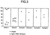
- Table V below reports push-out shear strengths recorded in psi. for mounted converter samples provided in accordance with the Examples, both before and after thermal aging. Values reported in Table V for each of the prior art Group A and Group B samples are averages of five sample measurements, while the data for the converters of the Examples are for individual measurements. Data points for sample results reported in Table V are shown in the Drawing, which plots shear strength values computed for each of the different sample types as calculated from the force required to cause axial movement of each mounted substrate within its mounting.
- the prior art Group B samples exhibited significantly improved aged shear strength levels when compared with the Group A samples. This result is attributed to the thermal protection afforded the intumescent mat by the refractory fiber substrate wrapping around the substrate.
Landscapes
- Chemical & Material Sciences (AREA)
- Engineering & Computer Science (AREA)
- Chemical Kinetics & Catalysis (AREA)
- Mechanical Engineering (AREA)
- General Engineering & Computer Science (AREA)
- Combustion & Propulsion (AREA)
- Toxicology (AREA)
- Health & Medical Sciences (AREA)
- Organic Chemistry (AREA)
- Ceramic Engineering (AREA)
- Materials Engineering (AREA)
- Exhaust Gas After Treatment (AREA)
- Exhaust Gas Treatment By Means Of Catalyst (AREA)
- Catalysts (AREA)
Applications Claiming Priority (2)
| Application Number | Priority Date | Filing Date | Title |
|---|---|---|---|
| US49557 | 1979-06-18 | ||
| US4955797P | 1997-06-13 | 1997-06-13 |
Publications (2)
| Publication Number | Publication Date |
|---|---|
| EP0884459A2 true EP0884459A2 (de) | 1998-12-16 |
| EP0884459A3 EP0884459A3 (de) | 2002-12-11 |
Family
ID=21960456
Family Applications (1)
| Application Number | Title | Priority Date | Filing Date |
|---|---|---|---|
| EP98109695A Withdrawn EP0884459A3 (de) | 1997-06-13 | 1998-05-28 | Überzogene Katalysatorträger und Halterungen |
Country Status (4)
| Country | Link |
|---|---|
| US (1) | US6077483A (de) |
| EP (1) | EP0884459A3 (de) |
| JP (1) | JPH1136853A (de) |
| CN (1) | CN1098971C (de) |
Cited By (10)
| Publication number | Priority date | Publication date | Assignee | Title |
|---|---|---|---|---|
| WO1999040300A1 (de) * | 1998-02-03 | 1999-08-12 | Emitec Gesellschaft Für Emissionstechnologie Mbh | Katalytische abgasreinigungseinrichtung und zugehörige ausgleichsschicht, insbesondere für kraftfahrzeuge |
| WO2003091182A1 (fr) * | 2002-04-26 | 2003-11-06 | Ngk Insulators, Ltd. | Procede de production d'une structure en nid d'abeille et structure en nid d'abeille |
| WO2005000466A1 (en) * | 2003-06-30 | 2005-01-06 | 3M Innovative Properties Company | Mounting mat for mounting monolith in a pollution control device |
| EP1403478A3 (de) * | 2002-09-30 | 2005-07-20 | Nichias Corporation | Ein Halterungsmaterial für einen Katalysator |
| US6946013B2 (en) | 2002-10-28 | 2005-09-20 | Geo2 Technologies, Inc. | Ceramic exhaust filter |
| EP1704920A1 (de) * | 2005-03-24 | 2006-09-27 | Ngk Insulators, Ltd. | Verfahren zu deren Herstellung von einer Wabenstruktur und Wabenstruktur |
| WO2007117934A3 (en) * | 2006-03-30 | 2007-12-13 | 3M Innovative Properties Co | Catalyst-carrier supporting material and catalytic converter |
| US7451849B1 (en) | 2005-11-07 | 2008-11-18 | Geo2 Technologies, Inc. | Substantially fibrous exhaust screening system for motor vehicles |
| US7574796B2 (en) | 2002-10-28 | 2009-08-18 | Geo2 Technologies, Inc. | Nonwoven composites and related products and methods |
| US7582270B2 (en) | 2002-10-28 | 2009-09-01 | Geo2 Technologies, Inc. | Multi-functional substantially fibrous mullite filtration substrates and devices |
Families Citing this family (52)
| Publication number | Priority date | Publication date | Assignee | Title |
|---|---|---|---|---|
| JP2000225340A (ja) * | 1998-11-30 | 2000-08-15 | Denso Corp | ハニカム構造体 |
| DE60006808T2 (de) * | 2000-08-21 | 2004-05-27 | Ford Global Technologies, LLC (n.d.Ges.d. Staates Delaware), Dearborn | Verhinderung eines frühen Ausfalls einer Abgasbehandlungsvorrichtung |
| DE10137897A1 (de) * | 2001-08-02 | 2003-02-20 | Emitec Emissionstechnologie | Kontraktionsbegrenzer für einen Wabenkörper |
| US7371352B2 (en) * | 2001-09-26 | 2008-05-13 | Siemens Power Generation, Inc. | Catalyst element having a thermal barrier coating as the catalyst substrate |
| US7541005B2 (en) * | 2001-09-26 | 2009-06-02 | Siemens Energy Inc. | Catalytic thermal barrier coatings |
| CN101053974B (zh) * | 2002-06-17 | 2011-03-23 | 日立金属株式会社 | 陶瓷蜂窝构造体的制造方法 |
| JP4001800B2 (ja) * | 2002-09-25 | 2007-10-31 | 日本碍子株式会社 | ハニカム触媒担体の製造方法 |
| US7572311B2 (en) | 2002-10-28 | 2009-08-11 | Geo2 Technologies, Inc. | Highly porous mullite particulate filter substrate |
| US20040097371A1 (en) * | 2002-11-19 | 2004-05-20 | Juzer Jangbarwala | Application of conductive adsorbents, activated carbon granules and carbon fibers as substrates in catalysis |
| US6774080B2 (en) * | 2002-11-25 | 2004-08-10 | Delphi Technologies, Inc. | Gas treatment device comprising SMSI material and methods for making and using the same |
| US7819176B2 (en) * | 2003-03-03 | 2010-10-26 | Paragon Airheater Technologies, Inc. | Heat exchanger having powder coated elements |
| US7841390B1 (en) | 2003-03-03 | 2010-11-30 | Paragon Airheater Technologies, Inc. | Heat exchanger having powder coated elements |
| DE10335130A1 (de) * | 2003-07-31 | 2005-02-24 | Blue Membranes Gmbh | Immobilisierung von Katalysatoren auf porösen Körpern auf Kohlenstoffbasis |
| JP4550434B2 (ja) * | 2004-01-15 | 2010-09-22 | 日本碍子株式会社 | セル構造体及びその製造方法 |
| US7645426B2 (en) * | 2004-04-14 | 2010-01-12 | 3M Innovative Properties Company | Sandwich hybrid mounting mat |
| DE102005002929A1 (de) * | 2005-01-21 | 2006-07-27 | Emitec Gesellschaft Für Emissionstechnologie Mbh | Faservlies zum Lagern eines Wabenkörpers in einer Abgasleitung |
| US20060242951A1 (en) * | 2005-04-29 | 2006-11-02 | Caterpillar Inc. | Refractory material retention device |
| DE602006020774D1 (de) * | 2005-10-13 | 2011-04-28 | 3M Innovative Properties Co | Mehrlagige befestigungsmatten und diese enthaltende vorrichtungen zur herabsetzung der umweltverschmutzung |
| JP2009512813A (ja) * | 2005-10-19 | 2009-03-26 | スリーエム イノベイティブ プロパティズ カンパニー | 多層実装マット及びそれを包含する汚染防止装置 |
| US7682577B2 (en) | 2005-11-07 | 2010-03-23 | Geo2 Technologies, Inc. | Catalytic exhaust device for simplified installation or replacement |
| US7211232B1 (en) | 2005-11-07 | 2007-05-01 | Geo2 Technologies, Inc. | Refractory exhaust filtering method and apparatus |
| US7682578B2 (en) | 2005-11-07 | 2010-03-23 | Geo2 Technologies, Inc. | Device for catalytically reducing exhaust |
| US7858554B2 (en) * | 2007-05-24 | 2010-12-28 | Geo2 Technologies, Inc. | Cordierite fiber substrate and method for forming the same |
| US8038759B2 (en) | 2005-11-16 | 2011-10-18 | Geoz Technologies, Inc. | Fibrous cordierite materials |
| US20070116617A1 (en) * | 2005-11-21 | 2007-05-24 | Lawrukovich Michael P | Exhaust treatment device comprising lock-seam and methods of assembling the same |
| US7444805B2 (en) | 2005-12-30 | 2008-11-04 | Geo2 Technologies, Inc. | Substantially fibrous refractory device for cleaning a fluid |
| US7722828B2 (en) | 2005-12-30 | 2010-05-25 | Geo2 Technologies, Inc. | Catalytic fibrous exhaust system and method for catalyzing an exhaust gas |
| US7563415B2 (en) | 2006-03-03 | 2009-07-21 | Geo2 Technologies, Inc | Catalytic exhaust filter device |
| KR100836059B1 (ko) * | 2006-03-31 | 2008-06-09 | 주식회사 엘지화학 | 점토를 포함하는 세라믹 필터 및 그 제조 방법 |
| EP2035666A4 (de) * | 2006-06-15 | 2010-05-19 | 3M Innovative Properties Co | Isoliertes doppelwandiges abgassystem und herstellungsverfahren dafür |
| US8522828B2 (en) * | 2006-06-15 | 2013-09-03 | 3M Innovative Properties Company | Insulated double-walled exhaust system component and method of making the same |
| JP4389903B2 (ja) * | 2006-06-27 | 2009-12-24 | トヨタ自動車株式会社 | エンジンの排気浄化装置 |
| US20080241007A1 (en) * | 2007-04-02 | 2008-10-02 | Delphi Technologies, Inc. | Catalytic converter with inner sheath and method for making the same |
| US8413445B2 (en) * | 2007-05-11 | 2013-04-09 | General Electric Company | Method and system for porous flame holder for hydrogen and syngas combustion |
| US8449831B2 (en) * | 2008-07-24 | 2013-05-28 | Cummins Filtration Ip, Inc. | Spin formed catalyst |
| US8316647B2 (en) * | 2009-01-19 | 2012-11-27 | General Electric Company | System and method employing catalytic reactor coatings |
| US20100288704A1 (en) * | 2009-05-12 | 2010-11-18 | Jeffrey Michael Amsden | Flow-Through Substrate Assemblies and Methods for Making and Using Said Assemblies |
| AT508322B1 (de) * | 2009-06-05 | 2012-04-15 | Boehler Schmiedetechnik Gmbh & Co Kg | Verfahren zur warmformgebung eines werkstückes |
| GB2475097A (en) * | 2009-11-06 | 2011-05-11 | Total Vehicle Technology Ltd | Analysing an exhaust gas using an inorganic filter |
| FR2953151B1 (fr) * | 2009-12-01 | 2014-06-13 | Air Liquide | Reacteur catalytique comprenant une structure alveolaire catalytique et des elements optimisant le contact de cette structure alveolaire avec la paroi interne du reacteur |
| EP3120916B1 (de) * | 2010-02-22 | 2021-10-20 | Hitachi Metals, Ltd. | Herstellungsverfahren für eine keramikwabenstruktur |
| WO2012093481A1 (ja) * | 2011-01-06 | 2012-07-12 | イビデン株式会社 | 排ガス処理装置 |
| JP5778954B2 (ja) * | 2011-03-16 | 2015-09-16 | イビデン株式会社 | 排気管 |
| US8747510B2 (en) * | 2012-09-12 | 2014-06-10 | Tenneco Automotive Operating Company, Inc. | Method of installing a multi-layer batt, blanket or mat in an exhaust gas aftertreatment or acoustic device |
| US10508584B2 (en) * | 2015-01-22 | 2019-12-17 | Cummins Emission Solutions, Inc. | Use of insulating paint on exhaust aftertreatment system components |
| US10598068B2 (en) | 2015-12-21 | 2020-03-24 | Emissol, Llc | Catalytic converters having non-linear flow channels |
| JP7402828B2 (ja) * | 2018-06-21 | 2023-12-21 | スリーエム イノベイティブ プロパティズ カンパニー | マット材料、それを作製する方法、汚染防止装置及び断熱材 |
| WO2020005663A1 (en) | 2018-06-29 | 2020-01-02 | Corning Incorporated | Ceramic honeycomb bodies having high-strength skin and manufacturing methods thereof |
| CN110398415B (zh) * | 2019-07-31 | 2022-04-22 | 南京航空航天大学 | 一种桥梁钢结构防腐涂层寿命预测方法 |
| GB201911702D0 (en) | 2019-08-15 | 2019-10-02 | Johnson Matthey Plc | Particulate filters |
| EP4077892B1 (de) | 2019-12-17 | 2025-03-19 | 3M Innovative Properties Company | Verfahren zur herstellung einer wärmedämmstruktur |
| CN111300811B (zh) * | 2020-02-25 | 2021-11-30 | 宁夏金梯氟塑防腐设备有限公司 | 耐强酸碱中芯加强耐正负压内外衬四氟管道及制作工艺 |
Citations (2)
| Publication number | Priority date | Publication date | Assignee | Title |
|---|---|---|---|---|
| US4863700A (en) | 1985-04-16 | 1989-09-05 | Stemcor | Monolithic catalytic converter mounting arrangement |
| US5376341A (en) | 1992-07-24 | 1994-12-27 | Corning Incorporated | Catalytic converter for motorcycles |
Family Cites Families (10)
| Publication number | Priority date | Publication date | Assignee | Title |
|---|---|---|---|---|
| US3441381A (en) * | 1965-06-22 | 1969-04-29 | Engelhard Ind Inc | Apparatus for purifying exhaust gases of an internal combustion engine |
| JPS4931714A (de) * | 1972-07-21 | 1974-03-22 | ||
| US3991254A (en) * | 1973-03-10 | 1976-11-09 | Nippondenso Co., Ltd. | High temperature insulating structure |
| US3916057A (en) * | 1973-08-31 | 1975-10-28 | Minnesota Mining & Mfg | Intumescent sheet material |
| US3958312A (en) * | 1974-01-18 | 1976-05-25 | British Leyland Motor Corporation Limited | Catalytic device for an exhaust system for an internal combustion engine |
| US4284457A (en) * | 1979-07-30 | 1981-08-18 | Ford Aerospace & Communications Corp. | Method for bonding a skin member to honeycomb core |
| US4929429A (en) * | 1988-02-11 | 1990-05-29 | Minnesota Mining And Manufacturing Company | Catalytic converter |
| JPH074534B2 (ja) * | 1988-09-22 | 1995-01-25 | 日本碍子株式会社 | ハニカム構造体およびその製造法 |
| US4999168A (en) * | 1989-05-01 | 1991-03-12 | The Carborundum Company | Crack resistant intumescent sheet material |
| US5569455A (en) * | 1992-06-10 | 1996-10-29 | Shimadzu Corporation | Exhaust gas catalytic purifier construction |
-
1998
- 1998-05-28 EP EP98109695A patent/EP0884459A3/de not_active Withdrawn
- 1998-06-03 US US09/089,574 patent/US6077483A/en not_active Expired - Fee Related
- 1998-06-12 CN CN98114749A patent/CN1098971C/zh not_active Expired - Fee Related
- 1998-06-12 JP JP10164948A patent/JPH1136853A/ja not_active Withdrawn
Patent Citations (2)
| Publication number | Priority date | Publication date | Assignee | Title |
|---|---|---|---|---|
| US4863700A (en) | 1985-04-16 | 1989-09-05 | Stemcor | Monolithic catalytic converter mounting arrangement |
| US5376341A (en) | 1992-07-24 | 1994-12-27 | Corning Incorporated | Catalytic converter for motorcycles |
Cited By (16)
| Publication number | Priority date | Publication date | Assignee | Title |
|---|---|---|---|---|
| US7179429B1 (en) | 1998-02-03 | 2007-02-20 | Emitec Gesellschaft Fuer Emissionstechnologie Mbh | Catalytic exhaust-gas purification device and associated compensating layer, in particular for motor vehicles |
| WO1999040300A1 (de) * | 1998-02-03 | 1999-08-12 | Emitec Gesellschaft Für Emissionstechnologie Mbh | Katalytische abgasreinigungseinrichtung und zugehörige ausgleichsschicht, insbesondere für kraftfahrzeuge |
| WO2003091182A1 (fr) * | 2002-04-26 | 2003-11-06 | Ngk Insulators, Ltd. | Procede de production d'une structure en nid d'abeille et structure en nid d'abeille |
| US7276276B2 (en) | 2002-04-26 | 2007-10-02 | Ngk Insulators, Ltd. | Honeycomb structure producing method, and honeycomb structure |
| US7306773B2 (en) | 2002-09-30 | 2007-12-11 | Nichias Corporation | Holding material for catalytic converter |
| EP1403478A3 (de) * | 2002-09-30 | 2005-07-20 | Nichias Corporation | Ein Halterungsmaterial für einen Katalysator |
| US6946013B2 (en) | 2002-10-28 | 2005-09-20 | Geo2 Technologies, Inc. | Ceramic exhaust filter |
| US7550117B2 (en) | 2002-10-28 | 2009-06-23 | Geo2 Technologies, Inc. | Nonwoven composites and related products and processes |
| US7574796B2 (en) | 2002-10-28 | 2009-08-18 | Geo2 Technologies, Inc. | Nonwoven composites and related products and methods |
| US7582270B2 (en) | 2002-10-28 | 2009-09-01 | Geo2 Technologies, Inc. | Multi-functional substantially fibrous mullite filtration substrates and devices |
| WO2005000466A1 (en) * | 2003-06-30 | 2005-01-06 | 3M Innovative Properties Company | Mounting mat for mounting monolith in a pollution control device |
| US9494071B2 (en) | 2003-06-30 | 2016-11-15 | 3M Innovative Properties Company | Mounting mat for mounting monolith in a pollution control device |
| EP1704920A1 (de) * | 2005-03-24 | 2006-09-27 | Ngk Insulators, Ltd. | Verfahren zu deren Herstellung von einer Wabenstruktur und Wabenstruktur |
| US7560154B2 (en) | 2005-03-24 | 2009-07-14 | Ngk Insulators, Ltd. | Method for manufacturing honeycomb structure and the honeycomb structure |
| US7451849B1 (en) | 2005-11-07 | 2008-11-18 | Geo2 Technologies, Inc. | Substantially fibrous exhaust screening system for motor vehicles |
| WO2007117934A3 (en) * | 2006-03-30 | 2007-12-13 | 3M Innovative Properties Co | Catalyst-carrier supporting material and catalytic converter |
Also Published As
| Publication number | Publication date |
|---|---|
| CN1098971C (zh) | 2003-01-15 |
| CN1208811A (zh) | 1999-02-24 |
| US6077483A (en) | 2000-06-20 |
| JPH1136853A (ja) | 1999-02-09 |
| EP0884459A3 (de) | 2002-12-11 |
Similar Documents
| Publication | Publication Date | Title |
|---|---|---|
| US6077483A (en) | Coated catalytic converter substrates and mounts | |
| EP1348841B1 (de) | Halterungsmaterial für einen katalytischen Umwandler und Verfahren zu seiner Herstellung | |
| KR101756077B1 (ko) | 가요성 가장자리 보호제를 구비하는 장착 매트 및 장착 매트를 통합한 배기 가스 처리 장치 | |
| EP1626037B1 (de) | Wabenstruktur und herstellungsverfahren dafür | |
| CN1131093C (zh) | 低温排气处理装置用的非晶形非膨胀无机纤维衬垫 | |
| EP1550494B1 (de) | Wabenstruktur | |
| EP0554104B1 (de) | Wabenförmige keramische Struktur mit Nuten und einer Aussenschicht und Verfahren zu ihrer Herstellung | |
| EP2105183B1 (de) | Wabenfilter | |
| KR100818476B1 (ko) | 허니컴 구조체 및 그 제조 방법 | |
| EP2513442B1 (de) | Abgasbehandlungsvorrichtung | |
| US20070163250A1 (en) | Highly insulated exhaust manifold | |
| EP1780385B1 (de) | Wabenstruktur | |
| EP0798042B1 (de) | Verfahren zur Herstellung keramischer wabenförmiger Träger oder Katalysatoren | |
| US20060240212A1 (en) | Honeycomb structure | |
| KR20000007527A (ko) | 코팅된 촉매 컨버터 기판 및 지지대 | |
| KR100778261B1 (ko) | 허니컴 구조체 | |
| EP0795075A1 (de) | Abgas-nachbehandlungsgerät mit erhöhter reibung zwischen wabenmonolith und einkapselung |
Legal Events
| Date | Code | Title | Description |
|---|---|---|---|
| PUAI | Public reference made under article 153(3) epc to a published international application that has entered the european phase |
Free format text: ORIGINAL CODE: 0009012 |
|
| AK | Designated contracting states |
Kind code of ref document: A2 Designated state(s): AT BE CH CY DE DK ES FI FR GB GR IE IT LI LU MC NL PT SE |
|
| AX | Request for extension of the european patent |
Free format text: AL;LT;LV;MK;RO;SI |
|
| PUAL | Search report despatched |
Free format text: ORIGINAL CODE: 0009013 |
|
| AK | Designated contracting states |
Kind code of ref document: A3 Designated state(s): AT BE CH CY DE DK ES FI FR GB GR IE IT LI LU MC NL PT SE |
|
| AX | Request for extension of the european patent |
Free format text: AL;LT;LV;MK;RO;SI |
|
| AKX | Designation fees paid | ||
| REG | Reference to a national code |
Ref country code: DE Ref legal event code: 8566 |
|
| STAA | Information on the status of an ep patent application or granted ep patent |
Free format text: STATUS: THE APPLICATION IS DEEMED TO BE WITHDRAWN |
|
| 18D | Application deemed to be withdrawn |
Effective date: 20030611 |