EP0884468A2 - Dispositif et procédé pour la récupération de chaleur des gaz d'échappement - Google Patents
Dispositif et procédé pour la récupération de chaleur des gaz d'échappement Download PDFInfo
- Publication number
- EP0884468A2 EP0884468A2 EP98110478A EP98110478A EP0884468A2 EP 0884468 A2 EP0884468 A2 EP 0884468A2 EP 98110478 A EP98110478 A EP 98110478A EP 98110478 A EP98110478 A EP 98110478A EP 0884468 A2 EP0884468 A2 EP 0884468A2
- Authority
- EP
- European Patent Office
- Prior art keywords
- air
- oxidant
- exhaust gas
- combustion
- oxygen
- Prior art date
- Legal status (The legal status is an assumption and is not a legal conclusion. Google has not performed a legal analysis and makes no representation as to the accuracy of the status listed.)
- Withdrawn
Links
- 238000000034 method Methods 0.000 title claims abstract description 48
- 239000007789 gas Substances 0.000 claims abstract description 160
- QVGXLLKOCUKJST-UHFFFAOYSA-N atomic oxygen Chemical compound [O] QVGXLLKOCUKJST-UHFFFAOYSA-N 0.000 claims abstract description 149
- 239000001301 oxygen Substances 0.000 claims abstract description 149
- 229910052760 oxygen Inorganic materials 0.000 claims abstract description 149
- 238000002485 combustion reaction Methods 0.000 claims abstract description 115
- 239000007800 oxidant agent Substances 0.000 claims abstract description 112
- 230000001590 oxidative effect Effects 0.000 claims abstract description 110
- 239000000203 mixture Substances 0.000 claims abstract description 40
- 239000000446 fuel Substances 0.000 claims description 71
- UGFAIRIUMAVXCW-UHFFFAOYSA-N Carbon monoxide Chemical compound [O+]#[C-] UGFAIRIUMAVXCW-UHFFFAOYSA-N 0.000 claims description 25
- 239000003546 flue gas Substances 0.000 claims description 25
- 238000011084 recovery Methods 0.000 claims description 15
- 230000009467 reduction Effects 0.000 claims description 5
- 239000012530 fluid Substances 0.000 claims description 3
- 238000001035 drying Methods 0.000 claims description 2
- 238000002156 mixing Methods 0.000 claims description 2
- 239000003208 petroleum Substances 0.000 claims description 2
- 238000000926 separation method Methods 0.000 claims description 2
- 239000003570 air Substances 0.000 description 108
- VNWKTOKETHGBQD-UHFFFAOYSA-N methane Chemical compound C VNWKTOKETHGBQD-UHFFFAOYSA-N 0.000 description 36
- 230000008569 process Effects 0.000 description 32
- 230000004048 modification Effects 0.000 description 18
- 238000012986 modification Methods 0.000 description 18
- 239000003345 natural gas Substances 0.000 description 18
- 239000012080 ambient air Substances 0.000 description 13
- 238000010304 firing Methods 0.000 description 9
- 238000010248 power generation Methods 0.000 description 6
- 238000009434 installation Methods 0.000 description 5
- 230000008901 benefit Effects 0.000 description 4
- MYMOFIZGZYHOMD-UHFFFAOYSA-N Dioxygen Chemical compound O=O MYMOFIZGZYHOMD-UHFFFAOYSA-N 0.000 description 3
- 238000004519 manufacturing process Methods 0.000 description 3
- 238000009420 retrofitting Methods 0.000 description 3
- 239000002918 waste heat Substances 0.000 description 3
- 239000000567 combustion gas Substances 0.000 description 2
- 238000010586 diagram Methods 0.000 description 2
- 230000000694 effects Effects 0.000 description 2
- XLYOFNOQVPJJNP-UHFFFAOYSA-N water Substances O XLYOFNOQVPJJNP-UHFFFAOYSA-N 0.000 description 2
- 239000006227 byproduct Substances 0.000 description 1
- 230000003197 catalytic effect Effects 0.000 description 1
- 230000008859 change Effects 0.000 description 1
- 238000006243 chemical reaction Methods 0.000 description 1
- 239000003245 coal Substances 0.000 description 1
- 230000000052 comparative effect Effects 0.000 description 1
- 230000006835 compression Effects 0.000 description 1
- 238000007906 compression Methods 0.000 description 1
- 230000007812 deficiency Effects 0.000 description 1
- 238000010790 dilution Methods 0.000 description 1
- 239000012895 dilution Substances 0.000 description 1
- 238000003113 dilution method Methods 0.000 description 1
- 230000003628 erosive effect Effects 0.000 description 1
- 238000000605 extraction Methods 0.000 description 1
- 238000010438 heat treatment Methods 0.000 description 1
- 239000003921 oil Substances 0.000 description 1
- 230000036284 oxygen consumption Effects 0.000 description 1
- 239000000047 product Substances 0.000 description 1
- 230000000153 supplemental effect Effects 0.000 description 1
- 230000009469 supplementation Effects 0.000 description 1
- 238000005496 tempering Methods 0.000 description 1
Images

Classifications
-
- F—MECHANICAL ENGINEERING; LIGHTING; HEATING; WEAPONS; BLASTING
- F23—COMBUSTION APPARATUS; COMBUSTION PROCESSES
- F23L—SUPPLYING AIR OR NON-COMBUSTIBLE LIQUIDS OR GASES TO COMBUSTION APPARATUS IN GENERAL ; VALVES OR DAMPERS SPECIALLY ADAPTED FOR CONTROLLING AIR SUPPLY OR DRAUGHT IN COMBUSTION APPARATUS; INDUCING DRAUGHT IN COMBUSTION APPARATUS; TOPS FOR CHIMNEYS OR VENTILATING SHAFTS; TERMINALS FOR FLUES
- F23L7/00—Supplying non-combustible liquids or gases, other than air, to the fire, e.g. oxygen, steam
-
- F—MECHANICAL ENGINEERING; LIGHTING; HEATING; WEAPONS; BLASTING
- F23—COMBUSTION APPARATUS; COMBUSTION PROCESSES
- F23C—METHODS OR APPARATUS FOR COMBUSTION USING FLUID FUEL OR SOLID FUEL SUSPENDED IN A CARRIER GAS OR AIR
- F23C1/00—Combustion apparatus specially adapted for combustion of two or more kinds of fuel simultaneously or alternately, at least one kind of fuel being either a fluid fuel or a solid fuel suspended in a carrier gas or air
-
- F—MECHANICAL ENGINEERING; LIGHTING; HEATING; WEAPONS; BLASTING
- F02—COMBUSTION ENGINES; HOT-GAS OR COMBUSTION-PRODUCT ENGINE PLANTS
- F02G—HOT GAS OR COMBUSTION-PRODUCT POSITIVE-DISPLACEMENT ENGINE PLANTS; USE OF WASTE HEAT OF COMBUSTION ENGINES; NOT OTHERWISE PROVIDED FOR
- F02G5/00—Profiting from waste heat of combustion engines, not otherwise provided for
- F02G5/02—Profiting from waste heat of exhaust gases
-
- F—MECHANICAL ENGINEERING; LIGHTING; HEATING; WEAPONS; BLASTING
- F23—COMBUSTION APPARATUS; COMBUSTION PROCESSES
- F23C—METHODS OR APPARATUS FOR COMBUSTION USING FLUID FUEL OR SOLID FUEL SUSPENDED IN A CARRIER GAS OR AIR
- F23C2201/00—Staged combustion
- F23C2201/10—Furnace staging
-
- F—MECHANICAL ENGINEERING; LIGHTING; HEATING; WEAPONS; BLASTING
- F23—COMBUSTION APPARATUS; COMBUSTION PROCESSES
- F23C—METHODS OR APPARATUS FOR COMBUSTION USING FLUID FUEL OR SOLID FUEL SUSPENDED IN A CARRIER GAS OR AIR
- F23C2202/00—Fluegas recirculation
- F23C2202/30—Premixing fluegas with combustion air
-
- F—MECHANICAL ENGINEERING; LIGHTING; HEATING; WEAPONS; BLASTING
- F23—COMBUSTION APPARATUS; COMBUSTION PROCESSES
- F23G—CREMATION FURNACES; CONSUMING WASTE PRODUCTS BY COMBUSTION
- F23G2206/00—Waste heat recuperation
- F23G2206/20—Waste heat recuperation using the heat in association with another installation
- F23G2206/202—Waste heat recuperation using the heat in association with another installation with an internal combustion engine
-
- Y—GENERAL TAGGING OF NEW TECHNOLOGICAL DEVELOPMENTS; GENERAL TAGGING OF CROSS-SECTIONAL TECHNOLOGIES SPANNING OVER SEVERAL SECTIONS OF THE IPC; TECHNICAL SUBJECTS COVERED BY FORMER USPC CROSS-REFERENCE ART COLLECTIONS [XRACs] AND DIGESTS
- Y02—TECHNOLOGIES OR APPLICATIONS FOR MITIGATION OR ADAPTATION AGAINST CLIMATE CHANGE
- Y02E—REDUCTION OF GREENHOUSE GAS [GHG] EMISSIONS, RELATED TO ENERGY GENERATION, TRANSMISSION OR DISTRIBUTION
- Y02E20/00—Combustion technologies with mitigation potential
- Y02E20/14—Combined heat and power generation [CHP]
-
- Y—GENERAL TAGGING OF NEW TECHNOLOGICAL DEVELOPMENTS; GENERAL TAGGING OF CROSS-SECTIONAL TECHNOLOGIES SPANNING OVER SEVERAL SECTIONS OF THE IPC; TECHNICAL SUBJECTS COVERED BY FORMER USPC CROSS-REFERENCE ART COLLECTIONS [XRACs] AND DIGESTS
- Y02—TECHNOLOGIES OR APPLICATIONS FOR MITIGATION OR ADAPTATION AGAINST CLIMATE CHANGE
- Y02T—CLIMATE CHANGE MITIGATION TECHNOLOGIES RELATED TO TRANSPORTATION
- Y02T10/00—Road transport of goods or passengers
- Y02T10/10—Internal combustion engine [ICE] based vehicles
- Y02T10/12—Improving ICE efficiencies
Definitions
- This invention relates to a method and apparatus for recovering sensible heat from a hot exhaust gas.
- Waste heat from exhaust gases has been used to reduce energy costs in Brayton-cycle and Diesel-cycle combustion processes for a number of years. Such waste heat is recovered by either extracting the heat in a boiler without additional combustion of a fuel, or by using the hot exhaust gas as a preheated oxidant, which is combusted with additional fuel.
- a heat recovery steam generation (HRSG) system is preferred due to the increased efficiency of such a combined cycle.
- HRSG heat recovery steam generation
- the capital cost of a heat recovery steam generation (HRSG) system necessary for extracting heat from the exhaust gas is high.
- NOx emissions from the gas turbine typically must be reduced using a flue gas denitrification system. The need for a denitrification system further increases the cost of the combined cycle process.
- the hot exhaust gas is used as a preheated oxidant and replaces the combustion air in an existing air-fuel fired boiler.
- a typical boiler has two sections; a high temperature radiant section and a lower temperature, convection section.
- the turbine exhaust gas has a lower oxygen content than the normally used combustion air. Because a greater volume of lower oxygen-content hot exhaust gas is needed to burn the same amount of fuel in the radiant section, less energy becomes available in the radiant section. As a result, the flue gas leaving the radiant section contains a higher level of sensible heat. The higher level of sensible heat in the flue gas leaving the radiant section of the boiler, in turn, increases the amount of energy available in the convection section. This causes an imbalance in the operation of the boiler, results in inefficiency and often derates the capacity of the boiler.
- a number of boiler modifications are therefore required to allow for the change of oxidant from air to hot turbine exhaust gas, and the resulting higher flue gas temperature and volume.
- Additional feed water preheater tubes and economizer tubes may need to be placed in, and the air heater may need to be removed from, the convection section.
- New burners and a new windbox may be required to handle the hot exhaust gas and provide adequate flame stability.
- the heat input may have to be reduced significantly to avoid erosion of the boiler tubes (i.e., to maintain the gas velocity within the original design limits). In general, each of these modifications significantly increases the cost of the retrofit.
- Another disadvantage of repowering is the increased NOx emission from the gas turbine and boiler.
- a catalytic deNOx system is typically required to reduce the level of NOx in the flue stream, which further increases the cost of repowering.
- a further object of the invention is to provide an apparatus and method, as described above, in which the level of NOx in the gas turbine exhaust gas is reduced in the downstream combustion process so that the overall NOx emission from the converted system does not exceed the NOx emission level of the air-fuel fired system prior to conversion.
- a method and apparatus are described for recovering sensible heat from a hot exhaust gas having an oxygen content of less than 21 vol% in a fuel-air fired combustion device.
- the hot exhaust gas and an oxygen-enriched oxidant stream comprising a gas having an oxygen content of greater than 21 vol% is introduced into the combustion process to form an oxidant mixture comprising hot exhaust gas, oxidant and any remaining air, the mixture having an average combined oxygen content of less than 21 vol%.
- the average combined oxygen content is below the 21 vol% of the air for which the combustion apparatus was designed, combustion at a level at least substantially equal to that achieved with air combustion is achieved, with less fuel, as a result of the sensible heat recovered from the hot exhaust gas. Further, because the oxygen content of the mixture is below that of the air, the sensible heat recovery is balanced between the sections of the boiler. Thus, the recovery of the sensible heat from the hot exhaust gas does not result in an imbalance in the operation of the combustion device. As a result, sensible heat can be recovered from the hot exhaust gas without requiring substantial modifications to a combustion device originally designed for air-fuel combustion.
- a combustion device typically a fuel fired boiler power plant is shown in Fig. 1.
- fuel and air are fed, by a fuel feed 4 and an air feed 2, respectively, to boiler 6.
- boiler 6 the air-fuel mixture is combusted to generate steam and produce electric power.
- a combustion device comprising boiler 6 in combination with a gas turbine 8, in a system in accordance with the present invention, is shown in Fig. 2.
- Air and fuel are fed, by fuel feed 4 and air feed 2, respectively, to boiler 6, which is designed for fuel-air combustion, in the same manner as described above.
- gas turbine 8 is provided with fuel and air through turbine fuel feed 10, and turbine air feed 12, respectively.
- Turbine 8 functions, in the usual manner, to combust the air-fuel mixture to provide power.
- turbine 8 generates a hot exhaust gas.
- a typical gas turbine exhaust gas will have a temperature of about 1000 to about 1100°F, and an oxygen content of about 13 to about 14%.
- a fuel-air fired combustion process is a process which, at least initially, combines fuel and air for combustion.
- a fuel-air fired combustion device is a device designed to carry out a fuel-air fired combustion process.
- the hot exhaust gas which has an oxygen content of less than 21 vol% and usually within the range of from 10 to 16 volume percent, is introduced into boiler 6 via hot exhaust feed 13.
- an oxygen-enriched oxidant having an oxygen content greater than 21 vol% is fed from an oxidant source 14 to boiler 6 via oxidant feed 16 to form an oxidant mixture of the air, hot exhaust gas and oxidant available for combustion within boiler 6.
- the mixture has an average combined oxygen concentration that is greater than that of the hot exhaust gas, but less than 21 vol%.
- Air, hot exhaust gas and oxygen-enriched oxidant may be used separately, or as an oxidant mixture, to burn the fuel in stages in order to reduce NOx emissions.
- the flow of air, hot exhaust gas, oxygen-enriched oxidant and fuel can be adjusted for any given boiler load to operate the boiler at optimum efficiency.
- the oxidant mixture of this invention does not require that the fluids making up the mixture be actually mixed.
- the fluids could be introduced separately to the combustion process or device and could interact with the fuel separate from one another in the combustion process or device.
- the oxygen concentration of the hot exhaust gas/air mixture is increased by providing an oxygen-enriched oxidant stream, the available heat in the radiant section of the boiler is increased. As a result, an excessive level of sensible heat is not provided to the convection section of the boiler, as occurs when the exhaust gas is used as an oxidant without oxygen supplementation. It is, therefore, not necessary to modify the boiler to account for this imbalance. For proper combustion without modification to the boiler, it would be expected that the oxygen content of the oxidant mixture should be raised to be substantially equal to that of air, (about 21 vol%).
- the amount of fuel saved in the boiler is substantially equal in BTU content to the amount of sensible heat recovered from the hot exhaust gas, for boilers designed to use ambient air without preheating.
- the apparent heat recovery efficiency of 100%, expressed in terms of fuel savings in lower heating values, is unexpected as the flue gas temperature, or temperature at which the hot turbine gas is discharged to the atmosphere after combustion in the boiler, is about 300 to about 400°F.
- typical heat recovery efficiency in an HRSG system in which hot turbine gas is cooled from about 1000-1100°F to about 300-400°F is only 60 to 70%.
- boiler 6 operates under combustion conditions similar to air-fuel combustion conditions for which boiler 6 was initially designed, without modification.
- the sensible heat of the hot exhaust gas can be recovered in any process furnace fired with ambient or mildly preheated air, including process furnaces that have a flue gas temperature that is higher than the temperature of the hot exhaust gas.
- a boiler is fired with natural gas and ambient air at a 1261 MMBtu LHV/hr.
- 601 MMBtu/hr of heat is available in the radiant section of the boiler from which a flue gas exits at a temperature of 2000° F.
- the available heat corresponds to 47.6% of the fuel input.
- a hot turbine exhaust gas is then substituted for the combustion air (Case 1B) such that the natural gas fired with the hot turbine exhaust gas provides the same total heat input. Because there is 338 MMBtu/hr of sensible heat contained in the turbine exhaust gas, the firing rate is reduced to 923 MMBtu/hr.
- the total volume of oxidant is increased from 14,378,000 SCFH to 17,067,000 SCFH, which can create an over-pressure problem.
- Available heat in the radiant section is reduced to 39.9% of the total energy input (fuel input plus sensible heat of turbine exhaust gas) and as a result, only 503 MMBtu/hr is available in the radiant section of the boiler, which is 98 MMBtu/hr less than the baseline.
- the sensible heat to the convective section of the boiler is increased by 98 MMBtu/hr, from 660 to 758 MMBtu/hr. This causes an imbalance in the heat distribution between the radiant section and the convective section of the boiler requiring the mechanical modification of the boiler to allow for the use of the hot exhaust gas as the oxidant.
- a boiler In a baseline process (Case 2A) a boiler is fired at a partial load with natural gas and ambient air at a rate of 1538 MMBtu LHV/hr. 732 MMBtu/hr of heat is available in the radiant section of the boiler corresponding to 47.3% of the fuel input. The boiler is then fired with natural gas and a turbine exhaust gas with oxygen addition (Case 2B) to provide the same total heat input. Since there are 338 MMBtu/hr of sensible heat contained in the turbine exhaust gas, the firing rate is reduced to 1200 MMBtu LHV/hr.
- Example 3A In a baseline process (Case 3A) the boiler of Example 2 is fired at full load with natural gas and combustion air at a rate of 2,707 MMBtu LHV/hr. 1289 MMBtu/hr of heat is available in the radiant section of the boiler. The available heat corresponds to 47.6% of the fuel input. The boiler is then fired with turbine exhaust gas and oxygen addition replacing a portion of the combustion air to provide the same total heat input. The firing rate is reduced to 2,370 MMBtu LHV/hr. The combustion air flow rate is reduced from 30,869,000 SCFH to 13,340,000 SCFH and 614,000 SCFH of oxygen is added to 17,067,000 SCFH of hot turbine exhaust gas.
- the flow rates of turbine exhaust gas and oxygen, and the oxygen concentration of the mixture (16.6 vol%) are the same as in Example 2.
- the average temperature of the oxidant mixture is 1,053°F.
- the average oxygen content of the mixed oxidant, including the air, is increased to 18.4 vol% and the temperature reduced to 654°F because only a portion of the combustion air is replaced with the oxygen enhanced turbine exhaust gas.
- Both the available heat (1289 MMBtu/hr) in the radiant section, and the sensible heat MMBtu/hr provided to the convective section of the boiler match the baseline numbers.
- the boiler designed for ambient air combustion can be operated by partially replacing the combustion air with an oxygen-enhanced exhaust gas, without boiler tube modifications.
- a much greater volume of hot exhaust gas can be used in the boiler by further reducing the amount of combustion air and providing additional oxygen.
- the maximum amount of gas turbine exhaust gas that can be handled by this boiler is about 30,039,000 SCFH, which corresponds to about 94.7 MW of power output from the gas turbine. At this rate no combustion air is used and about 1,800,000 SCFH of oxygen is required.
- Case 3C illustrates the use of an oxygen-enriched oxidant, instead of pure oxygen.
- the oxygen concentration of the oxygen-enriched oxidant is 24.4 vol% and the flow rate is 13,954,000 SCFH. These values are chosen to match the average oxygen concentration and the total flow rate of the air and oxygen mixture of Case 3B so that no combustion air is required. Therefore, the hot oxidant mixture with an oxygen concentration of 18.4% and a temperature of 654 F is equivalent to ambient air (at 21% O2 and 77°F) for this boiler and Case 3C becomes equivalent, in effect, to Case 3B.
- the oxygen concentration of the oxygen-enriched oxidant is relatively low, a large amount of oxygen-enriched oxidant must be mixed with the hot exhaust gas in order to make the resulting oxidant mixture equivalent to the original combustion air.
- the resulting oxidant mixture has a higher volume, a higher oxygen concentration and a lower temperature, compared to the use of pure oxygen.
- a boiler is fired at full load with natural gas and ambient air at 2,707 MMBtu/hr.
- the air has a preheat temperature of 400°F and, as a result, more energy (1,473 MMBtu/hr) is available in the radiant section of the boiler.
- the available heat corresponds to 50.95% of the total energy input (fuel input plus air preheat energy).
- the boiler is then fired with natural gas and turbine exhaust gas with oxygen addition to provide the same energy input and available heat.
- the firing rate is reduced to 2,478 MMBtu LHV/hr , which provides a fuel savings of 230 MMBtu/hr (compared to 338 MMBtu/hr in Case 3B).
- the combustion air flow rate is reduced from 30,869,00 SCFH to 12,730,000 SCFH and 976,000 SCFH of oxygen is added to 17,067,000 SCFH of hot turbine exhaust gas.
- the oxygen concentration of the mixture of turbine exhaust gas and oxygen is 18.2 vol%.
- the average temperature is 1,035°F.
- the average oxygen content of the mixed oxidant, including the air, is increased to 19.3 vol% and the temperature is reduced to 782°F because only a portion of the combustion air is replaced with the oxygen enhanced turbine exhaust gas.
- Case 4C illustrates the effect of using an oxygen-enriched oxidant, similar to Case 3C.
- the oxygen concentration of the oxygen-enriched oxidant is 26.5 vol% and the flow rate is 13,706,000 SCFH. With this oxidant, no combustion air is required and Case 4C becomes equivalent to Case 4B.
- the hot oxidant mixture with an oxygen concentration of 18.2% and a temperature of 1,035°F and the hot oxidant mixture with an oxygen concentration of 19.3% and a temperature of 782 F are both equivalent to preheated air (at 21% O2 and 400°F) for this boiler.
- the air preheat temperature was assumed to stay constant at 400°F although the combustion air flow rate was reduced from 30,869,000 to 12,730,000 SCFH. If no modifications are made to the original air preheater section of the boiler, the air preheat temperature becomes higher. Also, the boiler flue gas temperature, after the air preheater, increases. Therefore, actual fuel reduction would be higher and oxygen requirement lower. The excess heat available in the boiler flue gas can be recovered by replacing a portion of the air heater with a feed water heater or an oxygen preheater.
- Case 5B natural gas is fired with turbine exhaust gas without oxygen addition to provide the same available heat as in Case 5A.
- the firing rate is reduced to 152 MMBtu LVH/hr.
- the total volume of oxidant is increased from 2,058,000 SCFH to 2,390,000 SCFH. This increase may not cause an overcapacity problem for the existing flue gas recovery system.
- Fuel savings, compared to the baseline air case is 28 MMBtu/hr, or 83% of the sensible heat in the exhaust gas. Relatively high heat recovery efficiency is achieved in this process, without the addition of oxygen, because of the relatively low process temperature of 1,000°F.
- Case 5D natural gas is fired with turbine exhaust gas without oxygen addition, and without air, to provide the same available heat as in Case 5A.
- the firing rate is further reduced to 142 MMBtu LHV/hr.
- 110,000 SCFH of oxygen is added to 1,707,000 SCFH of hot turbine exhaust gas.
- the average oxygen content of the mixed oxidant is 18.8 vol.%.
- Example 6A As a baseline (Case 6A), a process furnace was fired at full load with natural gas and ambient air at a rate of 180.5 MMBtu LHV/hr. Only 64 MMBtu/hr of heat is available in the process furnace operating at a 2,400° F flue gas temperature. The available heat corresponds to 35.2% of the fuel input due to the high process temperature. As in Example 5, a 5.4 MW industrial scale gas turbine is added for power generation.
- Case 6D natural gas is fired with turbine exhaust gas with oxygen addition, and without air, to provide the same available heat as in Case 6A. 27,000 SCFH of oxygen is added (i.e. total oxygen flow rate of 88,000 SCFH) to replace the remaining air, and mixed with 1,707,000 SCFH of hot turbine exhaust gas. The firing rate is further reduced to 131.8 MMBtu LVH/hr. This additional fuel savings is attributable to replacement of air with oxygen. The average oxygen content of the mixed oxidant is 17.8 vol%. The apparent fuel savings corresponds to 144% of the sensible heat in the turbine exhaust gas. In both Case 6C and 6D, specific oxygen consumption is 0.076 ton of oxygen per MMBtu LHV of fuel saved.
- the method of the present invention can be practiced with any air-fuel fired combustion device including, but not limited to steam boilers, petroleum heaters, drying furnaces, high temperature process furnaces, and other ovens and kilns.
- the combustion device can be one fired with any suitable fuels including natural gas, oil and coal.
- the method of the present invention has been described primarily with regard to a gas turbine, the invention can be practiced with any piece of process equipment that generates a hot exhaust gas having an oxygen concentration of less than 21 vol%.
- Suitable hot exhaust gas generating means include, but are not limited to, gas turbines, incinerators, thermal oxidizers and high temperature air separation units.
- the hot exhaust gas will have a temperature of at least 400°F and an oxygen concentration of at least 5 vol%.
- the oxygen concentration of the hot exhaust gas will be at least 10 vol%.
- a typical turbine exhaust gas will have a temperature of about 1000 to 1100°F, and an oxygen content of about 13 to 14 vol%.
- the oxygen-enriched oxidant used to enhance the oxygen concentration of the hot exhaust gas will generally comprise at least 30 vol%, preferably comprises at least 80 vol%, and most preferably comprises at least 90 vol% oxygen. As shown in Examples 3 and 4, when the oxygen concentration of the oxygen-enriched oxidant is relatively low, a much greater amount of oxygen-enriched oxidant must be mixed with the hot exhaust gas. The resulting oxidant mixture has a higher volume, a higher oxygen concentration and a lower temperature, compared to the case in which the oxygen concentration of the oxygen-enriched oxidant is high.
- the oxygen enhanced hot exhaust gas can be substituted for all, or a portion of the combustion air.
- the average oxygen content of the mixture of the hot exhaust gas and the oxygen-enriched oxidant, excluding air, need only be about 1 to 5 percentage points by volume higher than that of the hot exhaust gas for most applications.
- several factors including the oxygen concentration and temperature of the hot exhaust gas, the temperature of combustion air and the type of fuel used in the boiler or process furnace, and the oxygen concentration of oxygen-enriched oxidant determine the amount of oxygen-enriched oxidant required.
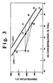
- the desired conditions can be related to the average oxygen concentration and temperature of the total oxidant mixture and illustrated in Fig. 3 to replace ambient temperature combustion air or preheated combustion air at 400°F.
- lines 1 and 2 represent "adiabatic oxidants" that provide the same available heat for combustion processes as air at temperatures of 77°F (ambient air) and 400°F (preheated air), respectively. These lines represent the adiabatic temperature and oxygen concentration of a hot oxidant.
- the hot oxidant is formed by burning a small amount of natural gas in air, which preheats the air and causes a corresponding reduction in oxygen concentration.
- air equivalent hot oxidant The hot oxidant represented by these lines is termed "air equivalent hot oxidant".
- temperature T h expressed in °F
- oxygen concentration of air equivalent hot oxidant, C o expressed in % assuming combustion air is at temperature T o °F
- T h T o + p (20.9 - C o )
- p is a proportionality constant that depends on type of fuel
- p is about 230 °F/O 2 % for natural gas.
- Point (3) represents the conditions of gas turbine exhaust gas used in the Examples, which is below the adiabatic point (2) on Line 1.
- the temperature difference between point (2) and point (3) is caused by the energy extracted and heat losses in the gas turbine system. (Note: the temperature at point (2) does not correspond to the adiabatic combustor temperature of the gas turbine since compression of air is not considered). Because of this deficiency in the energy content of the gas turbine exhaust gas, the use of gas turbine exhaust gas in a process furnace results in reduced available heat.
- the essence of this invention is to enhance the oxygen concentration of the turbine exhaust gas with oxygen-enriched gas and bring it to the "air equivalent hot oxidant" line. That is, the average combined oxygen concentration of the oxidant mixture of this invention is preferably within one volume percent of that of the air equivalent hot oxidant.
- Points (4) and (5) represent the oxidant conditions achieved in Example 3.
- the "air equivalent hot oxidant" line is reached without significant loss in temperature (Point (4)).
- the oxygen concentration of oxygen-enriched oxidant is relatively low (24.4% in Case 3C)
- a much greater amount of oxygen-enriched oxidant must be mixed with the hot exhaust gas.
- the resulting oxidant mixture has a higher volume, a higher oxygen concentration and a lower temperature (Point(5)).
- points (7) and (8) represent the oxidant conditions of Case 4B and Case 4C, respectively. Greater amounts of oxygen-enriched oxidant are required to reach the "air equivalent hot oxidant" line because of the higher energy content of preheated air, represented by Point (6). Point (4) represents the "air equivalent hot oxidant" used for Example 5, Case 5C and Case 6C. In all these cases, sensible heat in the turbine exhaust gas is fully recovered as fuel savings, regardless of the temperature of the process furnaces or the boiler, thus, demonstrating the benefits of the invention.
- the foregoing discussions are based on a hot turbine exhaust gas mixed "theoretically" with an oxygen-enriched oxidant to provide an oxidant mixture equivalent to combustion air, or air equivalent hot oxidant.
- the hot turbine exhaust gas which contains NOx generated in the gas turbine
- the oxygen-enriched oxidant into the boiler to burn fuel in two or more stages, with each stage using a different oxidant stream. It is preferred to burn the fuel, in the first stage of combustion, under fuel rich condition with the hot turbine exhaust gas. Additional air or oxygen-enriched gas may be mixed with the gas turbine exhaust gas.
- the second stage oxidant including oxygen-enriched oxidant and combustion air, if used, into the furnace in such a way to cause dilution of the oxidant with recirculated furnace gas prior to mixing with the fuel rich combustion products from the first stage of combustion.
- Oxidant dilution methods such as those described in U.S. Patent Numbers 5,601,425 or 5,242,296, can be used for the second stage combustion.
- the availability of oxygen-enriched and oxygen depleted oxidant provides substantial flexibility and benefits for low NOx combustion.
- flame temperature is reduced when turbine exhaust gas is used due to the reduced oxygen concentration, while it is increased when oxygen rich gas is used.
- the present invention provides an added benefit in optimizing the stoichiometric ratio and temperature of the first and second stages of combustion for the maximum reduction of NOx contained in the turbine exhaust gas, while minimizing generation of additional NOx in the combustion of fuel.
- Other known staged combustion and reburning techniques can be used in tandem with the present invention, to minimize the NO x content of the resulting flue gas.
- the boiler may be equipped with a flue gas recirculation system for steam temperature control or gas tempering or low NOx burner operation. Since oxygen depleted hot exhaust gas used in the present invention is equivalent to a mixture of combustion air and recirculated flue gas, the amount of gas recirculation can be reduced or eliminated. When gas recirculation is reduced the amount of oxygen-enriched oxidant should be reduced so as to balance the temperature requirement of the boiler.
Landscapes
- Engineering & Computer Science (AREA)
- Chemical & Material Sciences (AREA)
- Combustion & Propulsion (AREA)
- Mechanical Engineering (AREA)
- General Engineering & Computer Science (AREA)
- Air Supply (AREA)
Applications Claiming Priority (2)
| Application Number | Priority Date | Filing Date | Title |
|---|---|---|---|
| US08/871,623 US6200128B1 (en) | 1997-06-09 | 1997-06-09 | Method and apparatus for recovering sensible heat from a hot exhaust gas |
| US871623 | 1997-06-09 |
Publications (2)
| Publication Number | Publication Date |
|---|---|
| EP0884468A2 true EP0884468A2 (fr) | 1998-12-16 |
| EP0884468A3 EP0884468A3 (fr) | 1999-08-11 |
Family
ID=25357800
Family Applications (1)
| Application Number | Title | Priority Date | Filing Date |
|---|---|---|---|
| EP98110478A Withdrawn EP0884468A3 (fr) | 1997-06-09 | 1998-06-08 | Dispositif et procédé pour la récupération de chaleur des gaz d'échappement |
Country Status (7)
| Country | Link |
|---|---|
| US (1) | US6200128B1 (fr) |
| EP (1) | EP0884468A3 (fr) |
| KR (1) | KR100395150B1 (fr) |
| CN (1) | CN1179121C (fr) |
| BR (1) | BR9801798A (fr) |
| CA (1) | CA2239936C (fr) |
| ID (1) | ID20925A (fr) |
Cited By (4)
| Publication number | Priority date | Publication date | Assignee | Title |
|---|---|---|---|---|
| EP1344977A1 (fr) * | 2002-03-12 | 2003-09-17 | L'AIR LIQUIDE, Société Anonyme à Directoire et Conseil de Surveillance pour l'Etude et l'Exploitation des | Procédé de mise en oeuvre d'une chaudière de récupération de chaleur |
| EP1862529A3 (fr) * | 2006-03-30 | 2007-12-12 | L'air Liquide, Societe Anonyme Pour L'etude Et L'exploitation Des Procedes Georges Claude | Système de combustion avec une recirculation des gaz d'échappement et avec une admixtion d' hydrogène au carburant |
| WO2007020496A3 (fr) * | 2005-08-12 | 2008-01-31 | Air Liquide | Systeme auxiliaire d'air enrichi en oxygene destine a ameliorer le rendement d'un systeme de cogeneration |
| EP1456120A4 (fr) * | 2001-12-17 | 2011-06-22 | Praxair Technology Inc | Renforcement de production pour un reacteur |
Families Citing this family (26)
| Publication number | Priority date | Publication date | Assignee | Title |
|---|---|---|---|---|
| US20020127505A1 (en) * | 2001-01-11 | 2002-09-12 | Hisashi Kobayashi | Oxygen enhanced low nox combustion |
| CA2370253A1 (fr) * | 2001-02-01 | 2002-08-01 | Mark Entleutner | Appareil thermique producteur d'electricite |
| US6581369B1 (en) | 2001-08-27 | 2003-06-24 | General Electric Company | Heat recovery in test cells for gas turbine engines |
| ES2566798T3 (es) * | 2002-05-15 | 2016-04-15 | Praxair Technology, Inc. | Combustión con bajas emisiones de NOx |
| AU2003269127A1 (en) * | 2002-05-15 | 2003-12-02 | Praxair Technology, Inc. | Combustion with reduced carbon in the ash |
| FI20021223L (fi) * | 2002-06-24 | 2003-12-25 | Andritz Oy | Menetelmä ja poltin rumpu-uuneja varten |
| HUE059355T2 (hu) * | 2002-10-10 | 2022-11-28 | Lpp Comb Llc | Eljárás folyékony tüzelõanyagok elpárologtatására égetés céljára |
| US6595431B1 (en) | 2002-11-14 | 2003-07-22 | Dennis A. Lieske | Exhaust heat trap and redirecting system |
| FR2854943B1 (fr) * | 2003-05-13 | 2006-05-26 | Air Liquide | Procede de controle de bruleurs assurant le chauffage de canaux d'ecoulement de verre liquide |
| US7076957B2 (en) * | 2003-09-05 | 2006-07-18 | Praxair Technology, Inc. | Fluid heating and gas turbine integration method |
| US6957540B1 (en) * | 2004-04-28 | 2005-10-25 | Siemens Westinghouse Power Corporation | Multi-mode complex cycle power plant |
| US7185495B2 (en) | 2004-09-07 | 2007-03-06 | General Electric Company | System and method for improving thermal efficiency of dry low emissions combustor assemblies |
| JP4920597B2 (ja) | 2004-12-08 | 2012-04-18 | エル・ピー・ピー コンバスション エル・エル・シー | 液体炭化水素燃料を調整する方法および装置 |
| US20070251435A1 (en) * | 2006-04-27 | 2007-11-01 | Fisher Robert G | Fuel and emissions reduction power plant design using Oxygen for combustion and flue gas recirculation to minimize Carbon Dioxide and NOx emissions |
| US8529646B2 (en) * | 2006-05-01 | 2013-09-10 | Lpp Combustion Llc | Integrated system and method for production and vaporization of liquid hydrocarbon fuels for combustion |
| EP2067941A3 (fr) * | 2007-12-06 | 2013-06-26 | Alstom Technology Ltd | Centrale à cycle combiné avec recirculation des gaz brûlés et séparation de CO2 et méthode de fonctionnement d'une telle centrale à cycle combiné |
| US20090158978A1 (en) * | 2007-12-20 | 2009-06-25 | Foster Wheeler Energy Corporation | Method of controlling a process of generating power by oxyfuel combustion |
| US8375725B2 (en) * | 2008-03-14 | 2013-02-19 | Phillips 66 Company | Integrated pressurized steam hydrocarbon reformer and combined cycle process |
| SE1050114A1 (sv) * | 2010-02-05 | 2010-12-14 | Linde Ag | Förfarande vid förbränning av lågvärdigt bränsle |
| JP5451455B2 (ja) * | 2010-03-01 | 2014-03-26 | 大陽日酸株式会社 | バーナの燃焼方法 |
| US20120129112A1 (en) * | 2010-11-22 | 2012-05-24 | Foster Wheeler North America Corp. | Method Of And A System For Combusting Fuel In An Oxyfuel Combustion Boiler |
| US20120222426A1 (en) | 2011-03-04 | 2012-09-06 | Conocophillips Company | Integrated gas turbine, sagd boiler and carbon capture |
| US20120301834A1 (en) * | 2011-05-24 | 2012-11-29 | Her Majesty The Queen In Right Of Canada As Represented By The Minister Of Natural Resources | High pressure oxy-fired combustion system |
| MD4270C1 (ro) * | 2013-06-06 | 2014-08-31 | Юрие ПАНФИЛ | Instalaţie energetică pentru arderea combustibilului şi procedeu de utilizare a gazelor fumigene pentru arderea combustibilului în aceasta |
| US20150021031A1 (en) * | 2013-07-19 | 2015-01-22 | Conocophillips Company | Electric and fired steam generation systems |
| US9903588B2 (en) * | 2013-07-30 | 2018-02-27 | General Electric Company | System and method for barrier in passage of combustor of gas turbine engine with exhaust gas recirculation |
Family Cites Families (26)
| Publication number | Priority date | Publication date | Assignee | Title |
|---|---|---|---|---|
| US2110209A (en) * | 1934-10-13 | 1938-03-08 | Baker Perkins Co Inc | Furnace |
| US3868211A (en) * | 1974-01-11 | 1975-02-25 | Aqua Chem Inc | Pollutant reduction with selective gas stack recirculation |
| US4013023A (en) * | 1975-12-29 | 1977-03-22 | Envirotech Corporation | Incineration method and system |
| US4101632A (en) * | 1976-10-28 | 1978-07-18 | Aluminum Company Of America | Waste gas incineration control |
| JPS53148167A (en) * | 1977-05-28 | 1978-12-23 | Kawasaki Heavy Ind Ltd | Method of harmlessly burning waste gas and liquid |
| JPS5486823A (en) * | 1977-12-23 | 1979-07-10 | Mitsubishi Heavy Ind Ltd | Combustion with reduction of nitrogen oxide |
| US4474121A (en) * | 1981-12-21 | 1984-10-02 | Sterling Drug Inc. | Furnace control method |
| US4547150A (en) * | 1984-05-10 | 1985-10-15 | Midland-Ross Corporation | Control system for oxygen enriched air burner |
| US4923391A (en) * | 1984-08-17 | 1990-05-08 | American Combustion, Inc. | Regenerative burner |
| US4622007A (en) * | 1984-08-17 | 1986-11-11 | American Combustion, Inc. | Variable heat generating method and apparatus |
| US4861262A (en) * | 1984-08-17 | 1989-08-29 | American Combustion, Inc. | Method and apparatus for waste disposal |
| US4582005A (en) * | 1984-12-13 | 1986-04-15 | Aluminum Company Of America | Fuel burning method to reduce sulfur emissions and form non-toxic sulfur compounds |
| SE8306722L (sv) * | 1985-06-03 | 1985-06-07 | Ssab Svenskt Stal Ab | Sett att reglera ett forbrenningsforlopp |
| US4706612A (en) * | 1987-02-24 | 1987-11-17 | Prutech Ii | Turbine exhaust fed low NOx staged combustor for TEOR power and steam generation with turbine exhaust bypass to the convection stage |
| US4909727A (en) * | 1987-03-04 | 1990-03-20 | Combustion Tec, Inc. | Oxygen enriched continuous combustion in a regenerative furance |
| US4761132A (en) * | 1987-03-04 | 1988-08-02 | Combustion Tec, Inc. | Oxygen enriched combustion |
| DE3824813A1 (de) * | 1988-07-21 | 1990-01-25 | Arno Dipl Ing Schneider | Verfahren zum betrieb einer verbrennungsmotoren- und/oder einer gasturbinenanlage und vorrichtung zur durchfuehrung dieses verfahrens mit integrierter abgasnachbehandlung, insbesondere zur verwendung in kraft-waerme-kopplungssystemen |
| US5181475A (en) * | 1992-02-03 | 1993-01-26 | Consolidated Natural Gas Service Company, Inc. | Apparatus and process for control of nitric oxide emissions from combustion devices using vortex rings and the like |
| US5224334A (en) * | 1992-03-09 | 1993-07-06 | Radian Corporation | Low NOx cogeneration process and system |
| GB9212581D0 (en) * | 1992-06-13 | 1992-07-29 | Vert Investments Ltd | Glass melting furnace and method of operating the same |
| US5242296A (en) * | 1992-12-08 | 1993-09-07 | Praxair Technology, Inc. | Hybrid oxidant combustion method |
| DE4313102A1 (de) * | 1993-04-22 | 1994-10-27 | Sbw Sonderabfallentsorgung Bad | Verfahren zum Reduzieren der Abgasmengen zur Eliminierung von NO¶x¶-Emissionen bei der Verbrennung, vorzugsweise bei der Abfallverbrennung |
| US5402739A (en) * | 1993-10-27 | 1995-04-04 | Abboud; Harry I. | Closed loop incineration process |
| US5525053A (en) * | 1994-12-01 | 1996-06-11 | Wartsila Diesel, Inc. | Method of operating a combined cycle power plant |
| US5755818A (en) * | 1995-06-13 | 1998-05-26 | Praxair Technology, Inc. | Staged combustion method |
| US5823124A (en) * | 1995-11-03 | 1998-10-20 | Gas Research Institute | Method and system to reduced NOx and fuel emissions from a furnace |
-
1997
- 1997-06-09 US US08/871,623 patent/US6200128B1/en not_active Expired - Fee Related
-
1998
- 1998-06-01 ID IDP980805A patent/ID20925A/id unknown
- 1998-06-08 KR KR10-1998-0021017A patent/KR100395150B1/ko not_active Expired - Fee Related
- 1998-06-08 BR BR9801798A patent/BR9801798A/pt not_active IP Right Cessation
- 1998-06-08 EP EP98110478A patent/EP0884468A3/fr not_active Withdrawn
- 1998-06-08 CA CA002239936A patent/CA2239936C/fr not_active Expired - Fee Related
- 1998-06-08 CN CNB981096727A patent/CN1179121C/zh not_active Expired - Fee Related
Cited By (8)
| Publication number | Priority date | Publication date | Assignee | Title |
|---|---|---|---|---|
| EP1456120A4 (fr) * | 2001-12-17 | 2011-06-22 | Praxair Technology Inc | Renforcement de production pour un reacteur |
| EP1344977A1 (fr) * | 2002-03-12 | 2003-09-17 | L'AIR LIQUIDE, Société Anonyme à Directoire et Conseil de Surveillance pour l'Etude et l'Exploitation des | Procédé de mise en oeuvre d'une chaudière de récupération de chaleur |
| FR2837263A1 (fr) * | 2002-03-12 | 2003-09-19 | Air Liquide | Procede de mise en oeuvre d'une chaudiere de recuperation de chaleur |
| US6820432B2 (en) | 2002-03-12 | 2004-11-23 | L'air Liquide, S.A. | Method of operating a heat recovery boiler |
| WO2007020496A3 (fr) * | 2005-08-12 | 2008-01-31 | Air Liquide | Systeme auxiliaire d'air enrichi en oxygene destine a ameliorer le rendement d'un systeme de cogeneration |
| US7950217B2 (en) | 2005-08-12 | 2011-05-31 | American Air Liquide, Inc. | Oxygen-enriched air assisting system for improving the efficiency of cogeneration system |
| US8393138B2 (en) | 2005-08-12 | 2013-03-12 | American Air Liquide, Inc. | Oxygen-enriched air assisting system for improving the efficiency of cogeneration system |
| EP1862529A3 (fr) * | 2006-03-30 | 2007-12-12 | L'air Liquide, Societe Anonyme Pour L'etude Et L'exploitation Des Procedes Georges Claude | Système de combustion avec une recirculation des gaz d'échappement et avec une admixtion d' hydrogène au carburant |
Also Published As
| Publication number | Publication date |
|---|---|
| CN1179121C (zh) | 2004-12-08 |
| CN1201891A (zh) | 1998-12-16 |
| KR19990006738A (ko) | 1999-01-25 |
| CA2239936C (fr) | 2007-01-09 |
| CA2239936A1 (fr) | 1998-12-09 |
| KR100395150B1 (ko) | 2003-10-23 |
| ID20925A (id) | 1999-03-25 |
| US6200128B1 (en) | 2001-03-13 |
| BR9801798A (pt) | 1999-05-25 |
| EP0884468A3 (fr) | 1999-08-11 |
Similar Documents
| Publication | Publication Date | Title |
|---|---|---|
| US6200128B1 (en) | Method and apparatus for recovering sensible heat from a hot exhaust gas | |
| EP1992876B1 (fr) | Appareil de combustion | |
| US6247315B1 (en) | Oxidant control in co-generation installations | |
| JP4017521B2 (ja) | 酸素強化されたNOx低減燃焼 | |
| CA2733244C (fr) | Systeme de combustion comprenant une injection de vapeur ou d'eau | |
| US4706612A (en) | Turbine exhaust fed low NOx staged combustor for TEOR power and steam generation with turbine exhaust bypass to the convection stage | |
| US20090183660A1 (en) | Method for controlling the combustion air supply in a steam generator that is fueled with fossil fuels | |
| KR101701244B1 (ko) | 산소부화 연소장치, 그가 적용된 화력발전 시스템 및 그의 제어방법 | |
| CN106061908A (zh) | 具有优化的能量回收的燃烧方法和设施 | |
| WO2009110034A1 (fr) | Procédé de contrôle du débit des gaz d'échappement de recirculation principaux dans une chaudière à combustion d'oxygène et son appareil | |
| KR20100110826A (ko) | 순산소 연료 연소에 의해 전력을 생성하는 공정을 제어하는 방법 | |
| US6287111B1 (en) | Low NOx boilers, heaters, systems and methods | |
| US5823760A (en) | Method of operating a combined cycle power plant | |
| US6837702B1 (en) | Method of operating a combined cycle power plant | |
| EP2221535A2 (fr) | Systèmes pour la combustion étagée d'air et du combustible | |
| EP1936269A1 (fr) | Chaudière à combustion et procédé de combustion avec brûleurs de reburning à oxygène | |
| HUP0101129A2 (hu) | Eljárás és elrendezés gázok tűztérben való elégetésére | |
| WO2012064577A2 (fr) | Chaudière alimentée en oxy-combustible possédant une chambre de combustion alimentée séparément pour les fonctions de surchauffeur et de réchauffeur | |
| UA120401C2 (uk) | Спосіб спалення палива в доменних повітронагрівачах | |
| CN106895435A (zh) | 一种1000mw超超临界塔式炉先进脱硝运行法 |
Legal Events
| Date | Code | Title | Description |
|---|---|---|---|
| PUAI | Public reference made under article 153(3) epc to a published international application that has entered the european phase |
Free format text: ORIGINAL CODE: 0009012 |
|
| AK | Designated contracting states |
Kind code of ref document: A2 Designated state(s): DE ES FR IT |
|
| AX | Request for extension of the european patent |
Free format text: AL;LT;LV;MK;RO;SI |
|
| PUAL | Search report despatched |
Free format text: ORIGINAL CODE: 0009013 |
|
| AK | Designated contracting states |
Kind code of ref document: A3 Designated state(s): AT BE CH CY DE DK ES FI FR GB GR IE IT LI LU MC NL PT SE |
|
| AX | Request for extension of the european patent |
Free format text: AL;LT;LV;MK;RO;SI |
|
| RIC1 | Information provided on ipc code assigned before grant |
Free format text: 6F 02G 5/02 A, 6F 23L 7/00 B |
|
| 17P | Request for examination filed |
Effective date: 19990824 |
|
| AKX | Designation fees paid |
Free format text: DE ES FR IT |
|
| 17Q | First examination report despatched |
Effective date: 20021015 |
|
| STAA | Information on the status of an ep patent application or granted ep patent |
Free format text: STATUS: THE APPLICATION IS DEEMED TO BE WITHDRAWN |
|
| 18D | Application deemed to be withdrawn |
Effective date: 20040103 |