EP0884481A2 - Régulateur de position pneumatique - Google Patents
Régulateur de position pneumatique Download PDFInfo
- Publication number
- EP0884481A2 EP0884481A2 EP98110338A EP98110338A EP0884481A2 EP 0884481 A2 EP0884481 A2 EP 0884481A2 EP 98110338 A EP98110338 A EP 98110338A EP 98110338 A EP98110338 A EP 98110338A EP 0884481 A2 EP0884481 A2 EP 0884481A2
- Authority
- EP
- European Patent Office
- Prior art keywords
- setpoint
- valve
- force
- variable
- positioner according
- Prior art date
- Legal status (The legal status is an assumption and is not a legal conclusion. Google has not performed a legal analysis and makes no representation as to the accuracy of the status listed.)
- Withdrawn
Links
Images

Classifications
-
- F—MECHANICAL ENGINEERING; LIGHTING; HEATING; WEAPONS; BLASTING
- F15—FLUID-PRESSURE ACTUATORS; HYDRAULICS OR PNEUMATICS IN GENERAL
- F15B—SYSTEMS ACTING BY MEANS OF FLUIDS IN GENERAL; FLUID-PRESSURE ACTUATORS, e.g. SERVOMOTORS; DETAILS OF FLUID-PRESSURE SYSTEMS, NOT OTHERWISE PROVIDED FOR
- F15B9/00—Servomotors with follow-up action, e.g. obtained by feed-back control, i.e. in which the position of the actuated member conforms with that of the controlling member
- F15B9/02—Servomotors with follow-up action, e.g. obtained by feed-back control, i.e. in which the position of the actuated member conforms with that of the controlling member with servomotors of the reciprocatable or oscillatable type
- F15B9/08—Servomotors with follow-up action, e.g. obtained by feed-back control, i.e. in which the position of the actuated member conforms with that of the controlling member with servomotors of the reciprocatable or oscillatable type controlled by valves affecting the fluid feed or the fluid outlet of the servomotor
Definitions
- the invention relates to a pneumatic positioner for a pneumatic actuator, the manipulated variable of which is adjustable Setpoint size is adjusted, especially for positioning of diaphragm and piston operated control valves proportional to one pneumatic input signal.
- a pneumatic input signal is, for example, a setpoint pressure of 0.2 to 1 bar.
- Control devices with open systems consisting of nozzle and baffle plate are known for pilot control of a pneumatic booster valve that the Actuates piston or diaphragm drive with compressed air.
- pilot systems are with a permanent exhaust air at the pilot control (Nozzle baffle plate), which leads to a considerable loss of compressed air leads.
- the invention provides a pneumatic positioner created that has no permanent loss of compressed air.
- a displacement / force converter which converts the manipulated variable into an actual value force, and the Setpoint size is formed by a setpoint force in the comparator is compared with the actual value force.
- a comparison of forces allows a simple mechanical implementation of the comparator function, which also directly into a switching movement for control the valves can be implemented. If with this solution the setpoint is a pneumatic input signal, this is through a pressure / force converter converted into the setpoint force.
- the two valves realized by a double nozzle system.
- This double nozzle system contains two spaced from each other Nozzles and two closing bodies arranged between the nozzles, by a common compression spring or two separate compression springs apart and pressed against an associated nozzle end.
- Such a double nozzle system is very simple and inexpensive too realize; it also allows simple control using a Switching movement in one of two opposite Directions.
- the pneumatic positioner is particularly suitable for positioning of diaphragm or piston operated control valves proportional to one suitable for pneumatic input signal.
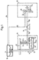
- the control loop of the positioner initially contains a pneumatic actuator 10 with a Control element 12 in the form of an actuating rod, which is the manipulated variable to the determining the flow of the valve, slide or the like Coupled element.
- the actuator 10 has a pressurized Diaphragm 14 with which the control element 12 is connected.
- the stroke movement H of the actuating element 12 is abandoned via a gear, preferably a cam gear with interchangeable cams, the one end of a compression spring 16, the other end of which loads one arm 18a of a two-armed lever 18, which is pivotally mounted in its center.
- a pressure / force converter having a by a setpoint pressurized membrane 22 presses on the same lever arm 18a as the compression spring 16, but in the opposite direction.
- the force exerted by the compression spring 16 on the lever arm 18a which is denoted by F, is "compared" in the catching region of the control circuit with the opposite force F setpoint exerted by the membrane 22, in that a balance between these forces is established.
- the pressure / force converter 20 thus forms a setpoint / actual value comparator with the compression spring 16, which is shown in a frame 24 in FIG. 1 and outputs a pivoting movement of the lever 18 in one direction or the other as a differential variable.
- the second lever arm 18b of the lever 18 sets that of the comparator 24 given differential quantity into a switching movement Xd, which is in one of two opposite directions.
- One of two valves 28, 30 becomes the direction of this switching movement of a pneumatic control system, which is shown in FIG Frame 32 is shown.
- both valves 28, 30 closed.
- the valve in question is opened while the other valve remains closed.
- the valve 30 lies in the flow path between a pneumatic pressure source, which emits a pressure P v , and the pressure chamber of the actuator 10, through which the diaphragm 14 is acted upon by pressure P a .
- the valve 28 lies in the flow path between a pressure relief opening of the actuator 10 and a pressure sink R, for example the free atmosphere.
- the comparator 24 supplies the difference quantity 0, and both valves 28, 30 are closed.
- the pressure chamber of the actuator 10 is closed and the membrane 14 remains in a position which is determined by the pressure in the pressure chamber of the actuator 10. If a malfunction is conveyed via the actuating element 12, the actual value force F ist changes and the two-armed lever 18 is pivoted. Depending on the direction of movement, valve 28 or valve 30 is opened while the other remains closed.
- the valve 28 is opened and the pressure chamber of the actuator 10 is opened to the pressure sink R so that the force exerted on the actuating element 12 via the membrane 14 decreases until a balance between the setpoint value Force and actual value force is reached and the valve 28 closes again.
- the valve 30 opens, the pressure in the pressure chamber of the actuator 10 increases, and the actual value force F ist is increased until equilibrium is restored, whereupon the valve 30 closes.
- the same functions occur when the setpoint pressure P should change. For example, if the setpoint force F should be greater, the valve 30 opens and the actual force F is increased, is restored to the equilibrium. When the setpoint pressure is reduced, on the other hand, the valve 28 opens and the actual value force F ist decreases accordingly until equilibrium is restored and the valve 28 closes.
- the two valves 28, 30 are in the preferred embodiment by the double nozzle system shown schematically in FIG realized.
- Two nozzles 40, 42 are coaxially spaced from one another arranged and protrude with their nozzle ends into a chamber 44, the one Connection A has to the outside.
- a stop housing 46 is arranged in the two plate-shaped closing bodies 48, 50 slidably received and are led.
- the closing body 48, 50 are by a common Compression spring 52 apart and towards each assigned nozzle end pressed.
- the stop housing 46 is with stops 54, 56 provided, against which the compression spring 52, the closing body 48, 50 presses, but their distance from each other is somewhat larger is the distance of the nozzle ends from each other, so that in Figure 2 shown the idle state of the closing body 48 sealing Nozzle end of the nozzle 40 and the closing body 50 sealing at the nozzle end the nozzle 42 abuts.
- the stop body 46 is coupled to the lever arm 18b and is moved by it against the nozzle 40 or the nozzle 42, as indicated in FIG. 2 by a double arrow.
- the connection A is connected to the pressure chamber of the pneumatic actuator 10 (FIG. 1).
- the nozzle 40 is connected to the pneumatic pressure source P v and the nozzle 42 to the pressure sink R.
- the nozzle 40 with the closing body 48 thus forms the valve 30 in FIG. 1, and the nozzle 42 with the closing body 50 forms the valve 28.
- the connection A is connected to the pressure chamber of the pneumatic actuator 10. You can see that only one connection is required.
- FIG. 3a The possible switching states of the double nozzle system are in the Figures 3a and 3b illustrates.
- Figure 3a is the stop housing 46 moves against the nozzle 40, which remains closed while the nozzle 50 is opened because the closing body 50 is held at the stop 54 becomes.
- the nozzle 40 is open while the nozzle 42nd remains closed.
Landscapes
- Engineering & Computer Science (AREA)
- Physics & Mathematics (AREA)
- Fluid Mechanics (AREA)
- Mechanical Engineering (AREA)
- General Engineering & Computer Science (AREA)
- Servomotors (AREA)
- Fluid-Driven Valves (AREA)
Applications Claiming Priority (2)
| Application Number | Priority Date | Filing Date | Title |
|---|---|---|---|
| DE29710015 | 1997-06-09 | ||
| DE29710015U | 1997-06-09 |
Publications (2)
| Publication Number | Publication Date |
|---|---|
| EP0884481A2 true EP0884481A2 (fr) | 1998-12-16 |
| EP0884481A3 EP0884481A3 (fr) | 2000-09-27 |
Family
ID=8041364
Family Applications (1)
| Application Number | Title | Priority Date | Filing Date |
|---|---|---|---|
| EP98110338A Withdrawn EP0884481A3 (fr) | 1997-06-09 | 1998-06-05 | Régulateur de position pneumatique |
Country Status (1)
| Country | Link |
|---|---|
| EP (1) | EP0884481A3 (fr) |
Cited By (1)
| Publication number | Priority date | Publication date | Assignee | Title |
|---|---|---|---|---|
| DE102010007152A1 (de) * | 2010-02-05 | 2011-08-11 | Hoerbiger Automatisierungstechnik Holding GmbH, 86956 | Fluidbetätigter Stellantrieb an einer Armatur |
Family Cites Families (5)
| Publication number | Priority date | Publication date | Assignee | Title |
|---|---|---|---|---|
| US2789543A (en) * | 1953-07-02 | 1957-04-23 | Honeywell Regulator Co | Stabilized pneumatic regulator apparatus |
| US2814183A (en) * | 1956-05-25 | 1957-11-26 | Askania Regulator Co | Electro-hydraulic relay |
| GB794108A (en) * | 1957-06-18 | 1958-04-30 | Samson App Bau Ag | Improvements in or relating to fluid-pressure systems for controlling the positions of valves |
| US4938249A (en) * | 1986-10-30 | 1990-07-03 | United Technologies Corporation | Chip tolerant flapper |
| DE19540441A1 (de) * | 1995-10-27 | 1997-04-30 | Schubert & Salzer Control Syst | Mikroprozessorgesteuerter Stellungsregler |
-
1998
- 1998-06-05 EP EP98110338A patent/EP0884481A3/fr not_active Withdrawn
Non-Patent Citations (1)
| Title |
|---|
| None |
Cited By (7)
| Publication number | Priority date | Publication date | Assignee | Title |
|---|---|---|---|---|
| DE102010007152A1 (de) * | 2010-02-05 | 2011-08-11 | Hoerbiger Automatisierungstechnik Holding GmbH, 86956 | Fluidbetätigter Stellantrieb an einer Armatur |
| WO2011095351A1 (fr) | 2010-02-05 | 2011-08-11 | Hoerbiger Automatisierungstechnik Holding Gmbh | Servomoteur actionné par un fluide dans une robinetterie |
| CN102822536A (zh) * | 2010-02-05 | 2012-12-12 | 贺尔碧格自动化技术控股股份有限公司 | 在阀门上的流体操纵的伺服驱动装置 |
| US20130009080A1 (en) * | 2010-02-05 | 2013-01-10 | Hoerbiger Automatisierungstechnik Holding Gmbh | Fluid-operated actuating drive on a valve |
| US8973890B2 (en) * | 2010-02-05 | 2015-03-10 | Hoerbiger Automatisierungstechnik Holding Gmbh | Fluid-operated actuating drive on a valve |
| RU2548837C2 (ru) * | 2010-02-05 | 2015-04-20 | ХЁРБИГЕР Аутоматизирунгстехник Холдинг ГмбХ | Сервопривод трубопроводной арматуры, приводимый в действие текучей средой |
| CN102822536B (zh) * | 2010-02-05 | 2015-04-22 | 贺尔碧格自动化技术控股股份有限公司 | 在阀门上的流体操纵的伺服驱动装置 |
Also Published As
| Publication number | Publication date |
|---|---|
| EP0884481A3 (fr) | 2000-09-27 |
Similar Documents
| Publication | Publication Date | Title |
|---|---|---|
| DE4431330B4 (de) | Sitzventil mit Kraftrückkopplungssteuerung | |
| EP0681128A1 (fr) | Electrovanne | |
| EP0304610A2 (fr) | Dispositif de soupape à réglage | |
| DE3305092C2 (fr) | ||
| DE2417835A1 (de) | Sicherheits-ventilsteueranlage | |
| DE69401263T2 (de) | Proportionales elektromagnetisch gesteuertes druckluftventil | |
| DE19635368C1 (de) | Elektro-pneumatischer Stellungsregler | |
| DE3420631C2 (fr) | ||
| EP0092064A2 (fr) | Dispositif pour commander un organe coulissant, en particulier un tiroir d'un distributeur | |
| DE1917079C3 (de) | Pneumatischer Verstärker | |
| EP0884481A2 (fr) | Régulateur de position pneumatique | |
| DE3439086A1 (de) | Relaisventileinrichtung | |
| DE2654964A1 (de) | Kraftbegrenzungsvorrichtung fuer eine feststellbremsbetaetigungseinrichtung | |
| DE2928802C2 (de) | Druckmittelbetätigter Differenzdruckschalter | |
| DE2317312C2 (de) | Drucksteuerventil, insbesondere Bremsventil | |
| EP1518773B1 (fr) | Valve de commande de remorque pour un tracteur avec système de freinage contrôlé électronique | |
| EP0026504B1 (fr) | Dispositif modulateur dans un équipement de robinet de frein de mécanicien pour freins à air comprimé à action indirecte de véhicules ferroviaires | |
| DE19537493C1 (de) | Elektro-pneumatischer Stellungsregler | |
| DE2929578A1 (de) | Notventileinrichtung in pneumatischen oder hydraulischen steuerungsanlagen | |
| EP0124726A1 (fr) | Valve de commande pour remorques | |
| DE10355311A1 (de) | Anhängersteuerventil für Zugfahrzeug mit elektronisch geregelter Bremsanlage | |
| DE3208151C2 (de) | Druckübersetzer für pneumatische oder hydraulische Antriebe, insbesondere für Kraftfahrzeuge | |
| DE1269439B (de) | Steuereinrichtung mit zwei gleichachsig angeordneten, unter Federdruck in Schliessstellung gehaltenen Einzelventilen | |
| DE2626723A1 (de) | In abhaengigkeit von der fahrzeugbeladung steuerbarer bremskraftregler | |
| DE3809325A1 (de) | Tuerbetaetigungsvorrichtung |
Legal Events
| Date | Code | Title | Description |
|---|---|---|---|
| PUAI | Public reference made under article 153(3) epc to a published international application that has entered the european phase |
Free format text: ORIGINAL CODE: 0009012 |
|
| AK | Designated contracting states |
Kind code of ref document: A2 Designated state(s): DE FR GB IT |
|
| AX | Request for extension of the european patent |
Free format text: AL;LT;LV;MK;RO;SI |
|
| PUAL | Search report despatched |
Free format text: ORIGINAL CODE: 0009013 |
|
| AK | Designated contracting states |
Kind code of ref document: A3 Designated state(s): AT BE CH CY DE DK ES FI FR GB GR IE IT LI LU MC NL PT SE |
|
| AX | Request for extension of the european patent |
Free format text: AL;LT;LV;MK;RO;SI |
|
| AKX | Designation fees paid |
Free format text: DE FR GB IT |
|
| STAA | Information on the status of an ep patent application or granted ep patent |
Free format text: STATUS: THE APPLICATION IS DEEMED TO BE WITHDRAWN |
|
| 18D | Application deemed to be withdrawn |
Effective date: 20010328 |