EP0884490A2 - Lager mit Flüssigkeitsfilmdämpfung - Google Patents
Lager mit Flüssigkeitsfilmdämpfung Download PDFInfo
- Publication number
- EP0884490A2 EP0884490A2 EP98304563A EP98304563A EP0884490A2 EP 0884490 A2 EP0884490 A2 EP 0884490A2 EP 98304563 A EP98304563 A EP 98304563A EP 98304563 A EP98304563 A EP 98304563A EP 0884490 A2 EP0884490 A2 EP 0884490A2
- Authority
- EP
- European Patent Office
- Prior art keywords
- bearing
- projections
- steel sheet
- spring means
- casing
- Prior art date
- Legal status (The legal status is an assumption and is not a legal conclusion. Google has not performed a legal analysis and makes no representation as to the accuracy of the status listed.)
- Granted
Links
- 229910000831 Steel Inorganic materials 0.000 claims abstract description 20
- 239000010959 steel Substances 0.000 claims abstract description 20
- 238000004519 manufacturing process Methods 0.000 description 5
- 230000000694 effects Effects 0.000 description 4
- 238000003754 machining Methods 0.000 description 4
- 239000000463 material Substances 0.000 description 3
- 229910000897 Babbitt (metal) Inorganic materials 0.000 description 2
- 230000002238 attenuated effect Effects 0.000 description 2
- 238000005530 etching Methods 0.000 description 2
- 239000012530 fluid Substances 0.000 description 2
- 238000005452 bending Methods 0.000 description 1
- 238000013016 damping Methods 0.000 description 1
- 230000000873 masking effect Effects 0.000 description 1
- 230000004048 modification Effects 0.000 description 1
- 238000012986 modification Methods 0.000 description 1
- 229910001220 stainless steel Inorganic materials 0.000 description 1
- 239000010935 stainless steel Substances 0.000 description 1
Images

Classifications
-
- F—MECHANICAL ENGINEERING; LIGHTING; HEATING; WEAPONS; BLASTING
- F16—ENGINEERING ELEMENTS AND UNITS; GENERAL MEASURES FOR PRODUCING AND MAINTAINING EFFECTIVE FUNCTIONING OF MACHINES OR INSTALLATIONS; THERMAL INSULATION IN GENERAL
- F16C—SHAFTS; FLEXIBLE SHAFTS; ELEMENTS OR CRANKSHAFT MECHANISMS; ROTARY BODIES OTHER THAN GEARING ELEMENTS; BEARINGS
- F16C27/00—Elastic or yielding bearings or bearing supports, for exclusively rotary movement
- F16C27/02—Sliding-contact bearings
-
- F—MECHANICAL ENGINEERING; LIGHTING; HEATING; WEAPONS; BLASTING
- F16—ENGINEERING ELEMENTS AND UNITS; GENERAL MEASURES FOR PRODUCING AND MAINTAINING EFFECTIVE FUNCTIONING OF MACHINES OR INSTALLATIONS; THERMAL INSULATION IN GENERAL
- F16C—SHAFTS; FLEXIBLE SHAFTS; ELEMENTS OR CRANKSHAFT MECHANISMS; ROTARY BODIES OTHER THAN GEARING ELEMENTS; BEARINGS
- F16C2360/00—Engines or pumps
- F16C2360/23—Gas turbine engines
- F16C2360/24—Turbochargers
Definitions
- the present invention relates to a squeeze film damper bearing for supporting a rotary shaft, in particular a shaft which rotates at high speed, such as the shaft of a centrifugal compressor.
- Squeeze film damper bearings are bearings in which a fluid film is formed between a fixed surface and the bearing for support of a rotating shaft, thereby supporting the bearing by fluid film pressure.
- the bearing is particularly characterised by its ability to damp any vibration of the shaft being rotated at high speed, and is very useful as a bearing for a turbocompressor, a turbocharger or the like.
- a typical example of a squeeze film damper bearing is disclosed in JP-A-58-109718 wherein an oil film is formed by supplying oil into a gap between a fixed support surface and an outer ring presser of a roller bearing.
- the presser is supported by a number of bolts which extend parallel to the shaft and enclose the shaft from the fixed side, which bolts also act as a spring means.
- the bearing is thus supported by the spring means and by the oil film provided in parallel with the spring means to thereby provide a squeeze film damper bearing.
- JP-A-8-261231 Japanese Patent Application No. 7-60683 (JP-A-8-261231), which is owned by the present applicant, aims to overcome this problem.
- the bearing disclosed in JP-A-8-261231 comprises a bearing bush for supporting a rotating shaft, a bearing casing surrounding the bearing bush and highly rigid concentricity spring means in the form of arcuate members between the bearing bush and the bearing casing.
- the bearing bush is stepped to have a reduced diameter at its opposed ends.
- Formed in the inner surface of the bearing casing is an annular groove opposed to the stepped portions of the bearing casing.
- the spring means is placed between the groove and the stepped portions and comprises arcuate members, i.e. circumferentially equiangularly divided portions of a cylinder.
- the arcuate members have outer projections which are parallel to the axis of the members and are equiangularly spaced apart to be at circumferentially opposite ends and at a midway portion.
- the arcuate members also have inner projections which are parallel to the axis and situated midway between the adjacent outer projections.
- the inner and outer projections contact the stepped portions of the bearing bush and support surfaces constituted by the bases of the grooves in the bearing casing, respectively, so that the bearing bush is supported by the bearing casing via the concentricity spring means to provide a gap between the outer periphery of the bearing bush and the inner surface of the bearing casing.
- An oiling passage communicates with the gap so as to generate oil film pressure as required.
- the bearing bush is supported by the support surfaces of the bearing casing via the projections on the concentricity spring means. As a result, a gap of predetermined size is formed between the outer periphery of the bearing bush and the inner surface of the bearing casing. Oil is supplied into the gap to generate oil film pressure as required.
- the high rigidity of the spring means will assure the presence of the oil film since it prevents the surface of the bearing bush from directly contacting the inner surface of the bearing casing even when a high vibrating or fluttering force is applied to the shaft.
- the spring means comprises circumferentially divided arcuate members which are slightly deformable by the pressure applied by the bearing casing to adapt to the shape of the gap between the outer periphery of the stepped portion of the bearing bush and the support surface of the bearing casing which extends around the bearing bush.
- the spring means usually used comprises two semi-circular members, i.e. upper and lower spring members, used in combination.
- Each of the spring members has outer projections parallel to the axis and provided at the apex and circumferentially opposite ends.
- Each spring member also has inner projections parallel to the axis and provided at 45° to the horizontal.
- Such spring members are produced by masking portions of a cylindrical body which correspond to the inner and outer projections as required and removing the other portions by etching. The etched portions are thus formed in a concave shape while the masked portions are formed as projections.
- the cylindrical body is then cut off along a plane passing through the centres of diametrically opposed outer projections and including the axis to provide the spring members.
- the height of each of the projections may be in the order of several hundred ⁇ m.
- the concentricity spring means used in the squeeze film damper bearing is produced by machining and etching from a thick cylindrical body, which results in a high material and manufacturing cost. Moreover, dimensional restrictions may make it difficult to vary the spring constant over a wide range in accordance with operating conditions.
- a squeeze film damper bearing which comprises a bearing bush for supporting a rotary shaft, a bearing casing extending around the bearing bush and concentricity spring means between the bearing bush and the bearing casing, the inner surface of the bearing casing being provided with a circumferential groove at least partially accommodating the spring means, characterised in that the spring means comprises an elongate steel sheet with a plurality of recesses formed in one surface of the steel sheet to provide a plurality of longitudinally aligned projections on the other surface of the steel sheet, the steel sheet being bent into a cylindrical shape, and that each of the projections has a curved surface with a generating line extending substantially parallel to the rotary shaft.
- the recesses in the concentricity spring means are formed on the inner surface of the steel sheet to provide the projections on the outer periphery of the steel sheet.
- the inner periphery of the spring means accommodated in the groove in the bearing casing contacts the outer periphery of the bearing bush.
- the tips of the projections on the outer periphery of the spring means contact the base of the groove in the bearing casing.
- the concentricity spring means may be produced by press-machining one surface of an elongate thin steel sheet to provide a plurality of longitudinally aligned projections on the other surface of the steel sheet and by bending the steel plate into a cylinder. This results in a reduction in material usage and manufacturing cost.
- the spring constant may be varied by varying the thickness and/or width of the steel sheet, the depth of the recesses (height of the projections) and/or the number of the recesses. The spring constant may thus readily be varied over a wide range.
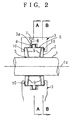
- Reference numeral 1 represents a rotary shaft which is rotated about an axis 1a at 60,000 to 80,000 rpm and has a diameter of about 20 to 30 mm; 2, a bearing bush or metallic bush which supports the shaft 1 via an oil film 5 and which has a diameter of about 60 to 80 mm and is divided into two parts; and 3, an annular bearing casing which covers or encloses the outer periphery and opposed side surfaces of the bush 2.
- the bearing casing 3 is provided on its inner periphery with a circumferential central groove 3a in which a concentricity spring 4 is accommodated.
- the bearing casing 3 comprises upper and lower casing halves 3b and 3c which are fastened together by bolts and nuts (not shown) passing through holes 3d.
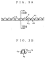
- the concentricity spring 4 is made of an elongate stainless steel sheet 4a with thickness of 0.3 to 0.7 mm. Recesses 4b of about 1 to 3 mm in depth are formed by press-machining a surface of the sheet 4a to provide a number of longitudinally aligned projections 4c on the other surface of the sheet 4a. The sheet 4a is then bent into a cylindrical or annular shape so that it extends around the outer periphery of the bearing metal 2 with the projections 4c directed outwardly.
- the projections 4c are semi-cylindrical but this is not essential. It will suffice if each of the projections 4c has a curved surface 4d with a generating line extending parallel to the axis of the rotating shaft 1.
- the projections may be a shallower segment or may be of sinusoidal shape.
- the two opposed sides of the projections 4c are closed by substantially semi-cylindrical flat sheets 4e.
- Reference numeral 7 denotes an oiling port; 8, a narrow passage which connects the port 7 with the groove 3a; 6, an oil film with thickness of about 0.1 to 0.2 mm to provide the squeeze film damper; 9, narrow passages which connect the oil film 6 to the oil film 5; and 10, oil seals.
- the tips of the projections 4c on the outer periphery of the spring means 4 contact the bottom surface of the groove 3a in the bearing casing 3.
- the bearing bush 2 is elastically supported by the bearing casing 3 via the concentricity spring means 4 with a gap of about 0.1 to 0.2 mm being formed between the outer periphery of the bearing bush 2 and the inner surface of the bearing casing 3. Oil is supplied through the port 7 to this gap to generate the oil film 6 so that any vibration or fluttering of the rotating shaft is attenuated.
- the concentricity spring means 4 is produced by press-machining the surface of the elongate thin steel sheet 4a, which results in reduction in material usage and manufacturing cost.
- the spring constant may be varied over a wide range by varying the thickness and/or width of the steel sheet 4a and/or the depth and/or the number of the recesses 4b.
- the present invention is not limited to the above embodiment and that various modifications may be made without departing from the scope of the invention.
- two spring means may be provided at respective lateral side edges of the bearing bush.
- the single groove 3a is formed in the bearing casing 3 but cooperating grooves 3a may be formed in the bearing casing 3 and the bearing metal 2, respectively.
- the projections 4c are on outer periphery of the concentricity spring means 4 but they may be provided on its inner periphery.
Landscapes
- Engineering & Computer Science (AREA)
- General Engineering & Computer Science (AREA)
- Mechanical Engineering (AREA)
- Support Of The Bearing (AREA)
Applications Claiming Priority (3)
| Application Number | Priority Date | Filing Date | Title |
|---|---|---|---|
| JP9152073A JPH112240A (ja) | 1997-06-10 | 1997-06-10 | スクイーズフィルムダンパ軸受 |
| JP152073/97 | 1997-06-10 | ||
| JP15207397 | 1997-06-10 |
Publications (3)
| Publication Number | Publication Date |
|---|---|
| EP0884490A2 true EP0884490A2 (de) | 1998-12-16 |
| EP0884490A3 EP0884490A3 (de) | 1999-09-15 |
| EP0884490B1 EP0884490B1 (de) | 2005-12-14 |
Family
ID=15532471
Family Applications (1)
| Application Number | Title | Priority Date | Filing Date |
|---|---|---|---|
| EP98304563A Expired - Lifetime EP0884490B1 (de) | 1997-06-10 | 1998-06-09 | Lager mit Flüssigkeitsfilmdämpfung |
Country Status (5)
| Country | Link |
|---|---|
| US (1) | US5988888A (de) |
| EP (1) | EP0884490B1 (de) |
| JP (1) | JPH112240A (de) |
| CA (1) | CA2240087C (de) |
| DE (1) | DE69832758T2 (de) |
Cited By (3)
| Publication number | Priority date | Publication date | Assignee | Title |
|---|---|---|---|---|
| EP0889253A3 (de) * | 1997-06-30 | 1999-09-15 | Ishikawajima-Harima Heavy Industries Co., Ltd. | Lagerkonstruktion für einen Turbolader |
| EP2392783A3 (de) * | 2005-11-16 | 2012-04-25 | Honeywell International Inc. | Zentrierfeder für Turboladerlager |
| EP2500544A4 (de) * | 2009-11-11 | 2018-01-31 | Toyota Jidosha Kabushiki Kaisha | Lagervorrichtung |
Families Citing this family (11)
| Publication number | Priority date | Publication date | Assignee | Title |
|---|---|---|---|---|
| DE19722629B4 (de) * | 1997-05-30 | 2006-07-27 | Dolmar Gmbh | Dichtungsanordnung |
| JP3636329B1 (ja) | 2004-08-17 | 2005-04-06 | 川崎重工業株式会社 | 軸受振動減衰機構 |
| DE102006028294A1 (de) * | 2006-06-20 | 2007-12-27 | Schaeffler Kg | Radiallageranordnung mit einer diese zentrierenden Spannringanordnung |
| US8162322B2 (en) * | 2006-10-25 | 2012-04-24 | Rexnord Industries, Llc | Hydrodynamic seal with circumferentially varying lift force |
| RU2598924C1 (ru) * | 2015-04-01 | 2016-10-10 | Открытое акционерное общество "Уфимское моторостроительное производственное объединение" ОАО "УМПО" | Упругодемпферная опора |
| JP6856404B2 (ja) * | 2017-02-24 | 2021-04-07 | 本田技研工業株式会社 | スクイズフィルムダンパベアリング装置 |
| CN111623036B (zh) * | 2019-02-27 | 2022-06-14 | 三菱重工业株式会社 | 挤压油膜阻尼器轴承及具备该挤压油膜阻尼器的旋转机械 |
| KR102463090B1 (ko) * | 2019-11-18 | 2022-11-03 | 한양대학교 에리카산학협력단 | 플로팅 슬리브 하이브리드 유체 베어링 |
| KR102463091B1 (ko) * | 2019-11-18 | 2022-11-03 | 한양대학교 에리카산학협력단 | 하이브리드 유체 베어링 |
| WO2021101211A1 (ko) * | 2019-11-18 | 2021-05-27 | 한양대학교 에리카산학협력단 | 하이브리드 유체 베어링 |
| WO2021101210A1 (ko) | 2019-11-18 | 2021-05-27 | 한양대학교 에리카산학협력단 | 플로팅 슬리브 하이브리드 유체 베어링 |
Citations (2)
| Publication number | Priority date | Publication date | Assignee | Title |
|---|---|---|---|---|
| JPS58109718A (ja) | 1981-12-08 | 1983-06-30 | ユナイテツド・テクノロジ−ズ・コ−ポレイシヨン | 軸受支持構造 |
| JPH08261231A (ja) | 1995-03-20 | 1996-10-08 | Ishikawajima Harima Heavy Ind Co Ltd | スクイーズフィルムダンパ軸受 |
Family Cites Families (8)
| Publication number | Priority date | Publication date | Assignee | Title |
|---|---|---|---|---|
| US3122399A (en) * | 1962-04-11 | 1964-02-25 | David U Hunter | Self-balancing bearing construction |
| DE2847979C2 (de) * | 1978-11-04 | 1984-09-06 | Robert Bosch Gmbh, 7000 Stuttgart | Federnder Einbauring für eine Lagernabe |
| US4222618A (en) * | 1978-12-29 | 1980-09-16 | Mechanical Technology Incorporated | Compliant hydrodynamic fluid bearing with resilient support matrix |
| US4440456A (en) * | 1983-03-24 | 1984-04-03 | General Motors Corporation | Squeeze film bearing mount |
| DE3628687A1 (de) * | 1986-08-23 | 1988-02-25 | Daimler Benz Ag | Lagerung der auf einem wellenende einer rotorwelle nebeneinander angeordneten laufraeder von verdichter und turbine im turbinengehaeuse |
| DE3704572A1 (de) * | 1987-02-13 | 1988-08-25 | Skf Gmbh | Federelement |
| US5116143A (en) * | 1990-12-20 | 1992-05-26 | Allied-Signal Inc. | High load capacity journal foil bearing |
| US5902049A (en) * | 1997-03-28 | 1999-05-11 | Mohawk Innovative Technology, Inc. | High load capacity compliant foil hydrodynamic journal bearing |
-
1997
- 1997-06-10 JP JP9152073A patent/JPH112240A/ja active Pending
-
1998
- 1998-06-02 US US09/089,160 patent/US5988888A/en not_active Expired - Lifetime
- 1998-06-09 CA CA002240087A patent/CA2240087C/en not_active Expired - Fee Related
- 1998-06-09 DE DE69832758T patent/DE69832758T2/de not_active Expired - Lifetime
- 1998-06-09 EP EP98304563A patent/EP0884490B1/de not_active Expired - Lifetime
Patent Citations (2)
| Publication number | Priority date | Publication date | Assignee | Title |
|---|---|---|---|---|
| JPS58109718A (ja) | 1981-12-08 | 1983-06-30 | ユナイテツド・テクノロジ−ズ・コ−ポレイシヨン | 軸受支持構造 |
| JPH08261231A (ja) | 1995-03-20 | 1996-10-08 | Ishikawajima Harima Heavy Ind Co Ltd | スクイーズフィルムダンパ軸受 |
Cited By (5)
| Publication number | Priority date | Publication date | Assignee | Title |
|---|---|---|---|---|
| EP0889253A3 (de) * | 1997-06-30 | 1999-09-15 | Ishikawajima-Harima Heavy Industries Co., Ltd. | Lagerkonstruktion für einen Turbolader |
| US6065875A (en) * | 1997-06-30 | 2000-05-23 | Ishikawajima-Harima Heavy Industries Co., Ltd. | Turbo charger bearing construction |
| EP2392783A3 (de) * | 2005-11-16 | 2012-04-25 | Honeywell International Inc. | Zentrierfeder für Turboladerlager |
| US8226296B2 (en) | 2005-11-16 | 2012-07-24 | Honeywell International Inc. | Centering mechanisms for turbocharger bearings |
| EP2500544A4 (de) * | 2009-11-11 | 2018-01-31 | Toyota Jidosha Kabushiki Kaisha | Lagervorrichtung |
Also Published As
| Publication number | Publication date |
|---|---|
| EP0884490B1 (de) | 2005-12-14 |
| DE69832758D1 (de) | 2006-01-19 |
| DE69832758T2 (de) | 2006-07-13 |
| CA2240087C (en) | 2004-03-30 |
| EP0884490A3 (de) | 1999-09-15 |
| CA2240087A1 (en) | 1998-12-10 |
| US5988888A (en) | 1999-11-23 |
| JPH112240A (ja) | 1999-01-06 |
Similar Documents
| Publication | Publication Date | Title |
|---|---|---|
| EP0884490B1 (de) | Lager mit Flüssigkeitsfilmdämpfung | |
| EP1619400B1 (de) | Ringförmiger Laufstützkörper für Wälzlagern | |
| US6149382A (en) | Vacuum pump with shaft bearing | |
| CN1077664C (zh) | 限制轴旋转速率的装置 | |
| AU567849B2 (en) | Radial friction bearing | |
| EP1895178A2 (de) | Elastischer Träger von einheitlicher Steifheit | |
| US5795077A (en) | Tilting pad journal bearing | |
| US6307295B1 (en) | Spindle motor and complex bearing assembly for use with the spindle motor | |
| US5895202A (en) | Molecular drag pump | |
| CA1192939A (en) | Pivoted segmental bearing | |
| WO2018016268A1 (ja) | フォイル軸受 | |
| US5997180A (en) | Circumferential flow type dynamic pressure bearing | |
| CN1055804A (zh) | 高刚度轴颈轴承 | |
| JPH08261231A (ja) | スクイーズフィルムダンパ軸受 | |
| JPH08261232A (ja) | スクイーズフィルムダンパ軸受 | |
| JPH0988950A (ja) | フォイルガス軸受 | |
| JPS61201917A (ja) | 浮動ブシユ軸受 | |
| JP2006189155A (ja) | 流体動圧軸受システム | |
| JP2000060063A (ja) | ファンモータ | |
| WO2014000797A1 (en) | Machine arrangement | |
| KR100224811B1 (ko) | 반구형 유체 베어링 및 그 제조방법 | |
| KR940000809Y1 (ko) | 축받이 장치 | |
| JP3202147B2 (ja) | 流体軸受装置 | |
| JP2005133849A (ja) | 軸受装置組立体及び水ポンプ装置 | |
| WO2023002734A1 (ja) | 流体機械 |
Legal Events
| Date | Code | Title | Description |
|---|---|---|---|
| PUAI | Public reference made under article 153(3) epc to a published international application that has entered the european phase |
Free format text: ORIGINAL CODE: 0009012 |
|
| AK | Designated contracting states |
Kind code of ref document: A2 Designated state(s): BE DE FR GB IT NL SE |
|
| AX | Request for extension of the european patent |
Free format text: AL;LT;LV;MK;RO;SI |
|
| PUAL | Search report despatched |
Free format text: ORIGINAL CODE: 0009013 |
|
| AK | Designated contracting states |
Kind code of ref document: A3 Designated state(s): AT BE CH CY DE DK ES FI FR GB GR IE IT LI LU MC NL PT SE |
|
| AX | Request for extension of the european patent |
Free format text: AL;LT;LV;MK;RO;SI |
|
| 17P | Request for examination filed |
Effective date: 20000228 |
|
| AKX | Designation fees paid |
Free format text: BE DE FR GB IT NL SE |
|
| 17Q | First examination report despatched |
Effective date: 20031219 |
|
| GRAP | Despatch of communication of intention to grant a patent |
Free format text: ORIGINAL CODE: EPIDOSNIGR1 |
|
| GRAS | Grant fee paid |
Free format text: ORIGINAL CODE: EPIDOSNIGR3 |
|
| GRAA | (expected) grant |
Free format text: ORIGINAL CODE: 0009210 |
|
| AK | Designated contracting states |
Kind code of ref document: B1 Designated state(s): BE DE FR GB IT NL SE |
|
| PG25 | Lapsed in a contracting state [announced via postgrant information from national office to epo] |
Ref country code: NL Free format text: LAPSE BECAUSE OF FAILURE TO SUBMIT A TRANSLATION OF THE DESCRIPTION OR TO PAY THE FEE WITHIN THE PRESCRIBED TIME-LIMIT Effective date: 20051214 Ref country code: BE Free format text: LAPSE BECAUSE OF FAILURE TO SUBMIT A TRANSLATION OF THE DESCRIPTION OR TO PAY THE FEE WITHIN THE PRESCRIBED TIME-LIMIT Effective date: 20051214 |
|
| REG | Reference to a national code |
Ref country code: GB Ref legal event code: FG4D |
|
| REF | Corresponds to: |
Ref document number: 69832758 Country of ref document: DE Date of ref document: 20060119 Kind code of ref document: P |
|
| PG25 | Lapsed in a contracting state [announced via postgrant information from national office to epo] |
Ref country code: SE Free format text: LAPSE BECAUSE OF FAILURE TO SUBMIT A TRANSLATION OF THE DESCRIPTION OR TO PAY THE FEE WITHIN THE PRESCRIBED TIME-LIMIT Effective date: 20060314 |
|
| NLV1 | Nl: lapsed or annulled due to failure to fulfill the requirements of art. 29p and 29m of the patents act | ||
| ET | Fr: translation filed | ||
| PLBE | No opposition filed within time limit |
Free format text: ORIGINAL CODE: 0009261 |
|
| STAA | Information on the status of an ep patent application or granted ep patent |
Free format text: STATUS: NO OPPOSITION FILED WITHIN TIME LIMIT |
|
| 26N | No opposition filed |
Effective date: 20060915 |
|
| PGFP | Annual fee paid to national office [announced via postgrant information from national office to epo] |
Ref country code: GB Payment date: 20140604 Year of fee payment: 17 |
|
| PGFP | Annual fee paid to national office [announced via postgrant information from national office to epo] |
Ref country code: IT Payment date: 20140613 Year of fee payment: 17 Ref country code: DE Payment date: 20140603 Year of fee payment: 17 |
|
| PGFP | Annual fee paid to national office [announced via postgrant information from national office to epo] |
Ref country code: FR Payment date: 20140609 Year of fee payment: 17 |
|
| REG | Reference to a national code |
Ref country code: DE Ref legal event code: R119 Ref document number: 69832758 Country of ref document: DE |
|
| PG25 | Lapsed in a contracting state [announced via postgrant information from national office to epo] |
Ref country code: IT Free format text: LAPSE BECAUSE OF NON-PAYMENT OF DUE FEES Effective date: 20150609 |
|
| GBPC | Gb: european patent ceased through non-payment of renewal fee |
Effective date: 20150609 |
|
| REG | Reference to a national code |
Ref country code: FR Ref legal event code: ST Effective date: 20160229 |
|
| PG25 | Lapsed in a contracting state [announced via postgrant information from national office to epo] |
Ref country code: DE Free format text: LAPSE BECAUSE OF NON-PAYMENT OF DUE FEES Effective date: 20160101 Ref country code: GB Free format text: LAPSE BECAUSE OF NON-PAYMENT OF DUE FEES Effective date: 20150609 |
|
| PG25 | Lapsed in a contracting state [announced via postgrant information from national office to epo] |
Ref country code: FR Free format text: LAPSE BECAUSE OF NON-PAYMENT OF DUE FEES Effective date: 20150630 |