EP0884507A1 - Mehrwegventile - Google Patents
Mehrwegventile Download PDFInfo
- Publication number
- EP0884507A1 EP0884507A1 EP98109261A EP98109261A EP0884507A1 EP 0884507 A1 EP0884507 A1 EP 0884507A1 EP 98109261 A EP98109261 A EP 98109261A EP 98109261 A EP98109261 A EP 98109261A EP 0884507 A1 EP0884507 A1 EP 0884507A1
- Authority
- EP
- European Patent Office
- Prior art keywords
- recess
- cone member
- pair
- cone
- valve housing
- Prior art date
- Legal status (The legal status is an assumption and is not a legal conclusion. Google has not performed a legal analysis and makes no representation as to the accuracy of the status listed.)
- Withdrawn
Links
- 238000007789 sealing Methods 0.000 claims description 2
- LYCAIKOWRPUZTN-UHFFFAOYSA-N Ethylene glycol Chemical compound OCCO LYCAIKOWRPUZTN-UHFFFAOYSA-N 0.000 description 5
- 239000002826 coolant Substances 0.000 description 4
- 238000001816 cooling Methods 0.000 description 3
- 238000010438 heat treatment Methods 0.000 description 3
- 238000010276 construction Methods 0.000 description 1
- 230000008878 coupling Effects 0.000 description 1
- 238000010168 coupling process Methods 0.000 description 1
- 238000005859 coupling reaction Methods 0.000 description 1
- 238000010586 diagram Methods 0.000 description 1
- WGCNASOHLSPBMP-UHFFFAOYSA-N hydroxyacetaldehyde Natural products OCC=O WGCNASOHLSPBMP-UHFFFAOYSA-N 0.000 description 1
- 238000002347 injection Methods 0.000 description 1
- 239000007924 injection Substances 0.000 description 1
- 239000000463 material Substances 0.000 description 1
Images
Classifications
-
- F—MECHANICAL ENGINEERING; LIGHTING; HEATING; WEAPONS; BLASTING
- F16—ENGINEERING ELEMENTS AND UNITS; GENERAL MEASURES FOR PRODUCING AND MAINTAINING EFFECTIVE FUNCTIONING OF MACHINES OR INSTALLATIONS; THERMAL INSULATION IN GENERAL
- F16K—VALVES; TAPS; COCKS; ACTUATING-FLOATS; DEVICES FOR VENTING OR AERATING
- F16K11/00—Multiple-way valves, e.g. mixing valves; Pipe fittings incorporating such valves
- F16K11/02—Multiple-way valves, e.g. mixing valves; Pipe fittings incorporating such valves with all movable sealing faces moving as one unit
- F16K11/08—Multiple-way valves, e.g. mixing valves; Pipe fittings incorporating such valves with all movable sealing faces moving as one unit comprising only taps or cocks
- F16K11/085—Multiple-way valves, e.g. mixing valves; Pipe fittings incorporating such valves with all movable sealing faces moving as one unit comprising only taps or cocks with cylindrical plug
- F16K11/0856—Multiple-way valves, e.g. mixing valves; Pipe fittings incorporating such valves with all movable sealing faces moving as one unit comprising only taps or cocks with cylindrical plug having all the connecting conduits situated in more than one plane perpendicular to the axis of the plug
Definitions
- the present invention relates to a multiple valve comprising a valve housing with a circular inner circumferential surface and cone members movable in the valve housing for opening and closing, respectively, flows between a plurality of connections distributed along the periphery of the valve housing.
- a particular field of use for the present invention is heat pump systems. In such systems, which are used in both heating and cooling operations, different flows of coolant must be capable of being switched in different directions in connection with alternating between heating and cooling operations.
- One object of the present invention is to realise a multiple valve with cone construction which permits a plurality of connection possibilities between different connections. This object is attained in that the present invention has been given the characterizing features as set forth in appended Claim 1.
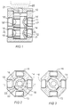
- valve housing 10 In the embodiment of the present invention illustrated in Fig. 1, double cone members 11, 12 are enclosed in a valve housing 10.
- the valve housing 10 is designed as a hollow body with an inner circular cross section, and the cone members 11, 12 are disposed to be pivotal in a plane at right angles to the plane of section.
- the outer contour of the valve housing 10 is octagonal in cross section.
- the cone members 11, 12 are designed as circular-cylindrical bodies with a central through-going axial recess 19 (see Fig. 2). They are also interconnected to one another axially offset along the centre line of the valve housing 10 so that pivot together within the valve housing 10.
- the pivotal movement of the cone members 11, 12 about the centre axis of the valve housing is realised by means of an operating device 20 which is intimated by broken lines in Fig. 1.
- the operating device 20 is connected to an upper cone member 11 via a spindle 21.
- Connections 13-16, 13'-16' in two axially discrete planes are provided in the valve housing 10 and discharge via through holes in the interior of the valve housing.
- a first arched recess 17 and a second arched recess 18 are provided in the cone members 11, 12.
- each respective arched recess 17, 18 places in communication two adjacent ports to the connections.
- the connection 13 is in communication with the connection 14 and the connection 15 is in communication with the connection 16.
- the ports to the connections in each respective plane lie offset 90° in relation to each other.
- the aperture diameter of the ports and the angular distance between the ports are selected such that the cone members 11, 12 reliably break the communication between the connections which are not communicated by the recesses 17, 18.
- Closed grooves 22, 23 run around each respective recess 17, 18, in which grooves O-rings or similar sealing devices are disposed.
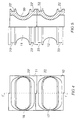
- the groove 22 is also shown in Figs. 4 and 5.
- Fig. 4 is a side elevation of the cone members 11, 12 showing how the recesses 17 and 18 are designed.
- the recesses 17, 18 each extend over almost half of the circumference of the cone member and are surrounded by the grooves 22, 23, respectively.
- the corresponding feature is also apparent from Fig. 5 which shows the cone members 11, 12 partly in cross section.
- the recesses 17, 18 are rounded-off and constitute a large aperture through the cone members. The apertures connect well to the ports of the connections. As a result, the pressure drop through the multiple valve will be slight.
- the cone members 11, 12 are manufactured from material possessing poor thermal conductivity, for example plastic.
- Each cone member may be composed of two injection moulded halves, which may further reduce their thermal conductivity.
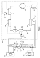
- the poor thermal conductivity in the cone members 11, 12 is a major advantage in an application according to Fig. 6.
- the heat pump system must be capable of both heating and cooling the indoor air.
- the switching between hot and cold operation takes place by means of the multiple valve according to the present invention which is disposed between two secondary sides of a heat pump 34.
- suitable coolant is employed, for example ethylene glycol (30.5 weight per cent).
- the working temperature of the medium varies between -10°C and +60°C, and the flow rate is about 600 l/h.
- the heat pump system includes a first heat exchanger 26 which, via a reservoir 27, is connected to a second heat exchanger 28.
- the second heat exchanger 28 is connected via a valve 29 to a third heat exchanger 30.
- the third heat exchanger 30 is connected via a tank 31 and a compressor 32 to a fourth heat exchanger 33. Pumps P ensure that the coolant is pumped around the system in different loops.
Landscapes
- Multiple-Way Valves (AREA)
- Engineering & Computer Science (AREA)
- General Engineering & Computer Science (AREA)
- Mechanical Engineering (AREA)
Applications Claiming Priority (2)
| Application Number | Priority Date | Filing Date | Title |
|---|---|---|---|
| SE9702236 | 1997-06-12 | ||
| SE9702236A SE9702236D0 (sv) | 1997-06-12 | 1997-06-12 | Flervägsventil |
Publications (1)
| Publication Number | Publication Date |
|---|---|
| EP0884507A1 true EP0884507A1 (de) | 1998-12-16 |
Family
ID=20407345
Family Applications (1)
| Application Number | Title | Priority Date | Filing Date |
|---|---|---|---|
| EP98109261A Withdrawn EP0884507A1 (de) | 1997-06-12 | 1998-05-22 | Mehrwegventile |
Country Status (2)
| Country | Link |
|---|---|
| EP (1) | EP0884507A1 (de) |
| SE (1) | SE9702236D0 (de) |
Cited By (4)
| Publication number | Priority date | Publication date | Assignee | Title |
|---|---|---|---|---|
| TR200002340A3 (tr) * | 2000-08-09 | 2001-02-21 | Oezbek Mustafa | Respiratör için silindir ve pistonlu valf. |
| US6663596B2 (en) | 2001-08-13 | 2003-12-16 | Scimed Life Systems, Inc. | Delivering material to a patient |
| WO2022184915A1 (de) * | 2021-03-05 | 2022-09-09 | Mack & Schneider Gmbh | Ventileinrichtung |
| WO2022268727A1 (en) * | 2021-06-25 | 2022-12-29 | Robert Bosch Gmbh | Multi-level rotary plug valve |
Citations (3)
| Publication number | Priority date | Publication date | Assignee | Title |
|---|---|---|---|---|
| US2414966A (en) * | 1945-02-15 | 1947-01-28 | Parker Appliance Co | Valve assembly |
| US3191628A (en) * | 1963-01-18 | 1965-06-29 | Creal E Kirkwood | Multi-port valve |
| EP0240059A1 (de) * | 1986-03-19 | 1987-10-07 | Van der Helm, Hermanus Cornelis | Druckentlastetes Drehventil |
-
1997
- 1997-06-12 SE SE9702236A patent/SE9702236D0/xx unknown
-
1998
- 1998-05-22 EP EP98109261A patent/EP0884507A1/de not_active Withdrawn
Patent Citations (3)
| Publication number | Priority date | Publication date | Assignee | Title |
|---|---|---|---|---|
| US2414966A (en) * | 1945-02-15 | 1947-01-28 | Parker Appliance Co | Valve assembly |
| US3191628A (en) * | 1963-01-18 | 1965-06-29 | Creal E Kirkwood | Multi-port valve |
| EP0240059A1 (de) * | 1986-03-19 | 1987-10-07 | Van der Helm, Hermanus Cornelis | Druckentlastetes Drehventil |
Cited By (6)
| Publication number | Priority date | Publication date | Assignee | Title |
|---|---|---|---|---|
| TR200002340A3 (tr) * | 2000-08-09 | 2001-02-21 | Oezbek Mustafa | Respiratör için silindir ve pistonlu valf. |
| WO2002011814A1 (de) * | 2000-08-09 | 2002-02-14 | Oezbek Mustafa | Ventil mit zylinder und kolben für respirator |
| US6663596B2 (en) | 2001-08-13 | 2003-12-16 | Scimed Life Systems, Inc. | Delivering material to a patient |
| US7270654B2 (en) | 2001-08-13 | 2007-09-18 | Boston Scientific Scimed, Inc. | Delivering material to a patient |
| WO2022184915A1 (de) * | 2021-03-05 | 2022-09-09 | Mack & Schneider Gmbh | Ventileinrichtung |
| WO2022268727A1 (en) * | 2021-06-25 | 2022-12-29 | Robert Bosch Gmbh | Multi-level rotary plug valve |
Also Published As
| Publication number | Publication date |
|---|---|
| SE9702236D0 (sv) | 1997-06-12 |
Similar Documents
| Publication | Publication Date | Title |
|---|---|---|
| US20240035581A1 (en) | Multi-port valve, and thermal management system provided with same and application thereof | |
| US6295828B1 (en) | Apparatus for switching a refrigerant channel of an air conditioner having cooling and warming functions | |
| JP7374062B2 (ja) | 流路切換バルブ | |
| US12404940B2 (en) | Multi-port valve and thermal management system having multi-port valve | |
| US12013042B2 (en) | Multiway valve with cartridge and fluid mechanics inserts | |
| JP2018071622A (ja) | 制御バルブ | |
| US5630447A (en) | Pipe for geothermal heating and cooling systems | |
| KR102550127B1 (ko) | 차량의 열관리 시스템용 통합 밸브 조립체 및 열관리 시스템 | |
| US12319116B2 (en) | Multi-ports valve and thermal management system having same | |
| US12372159B2 (en) | Thermal management system and valve thereof | |
| EP4386239B1 (de) | Temperatursteuerungssystem, fahrzeug, energiespeichersystem und mehrwegeventil | |
| CN114923003B (zh) | 可切换多个通道流通状态的控制阀 | |
| WO1989000663A1 (en) | Manifold | |
| EP0884507A1 (de) | Mehrwegventile | |
| CN116568951B (zh) | 多通路阀组件、多通路阀总成及热管理系统 | |
| KR102773478B1 (ko) | 이진 모드 유체 밸브 | |
| CN114838164B (zh) | 控制阀 | |
| CN219510182U (zh) | 六通阀及温度控制系统 | |
| CN219388688U (zh) | 转轴管式多通阀、热管理系统以及车辆 | |
| CN216200948U (zh) | 四通阀 | |
| CN217440851U (zh) | 控制阀 | |
| CN114688769B (zh) | 一种膨胀阀以及换热装置 | |
| EP3260746A1 (de) | Stromventil | |
| CN222669001U (zh) | 用于冷媒的多通阀、热管理系统及车辆 | |
| CN116045029A (zh) | 流路切换阀和流路控制系统 |
Legal Events
| Date | Code | Title | Description |
|---|---|---|---|
| PUAI | Public reference made under article 153(3) epc to a published international application that has entered the european phase |
Free format text: ORIGINAL CODE: 0009012 |
|
| AK | Designated contracting states |
Kind code of ref document: A1 Designated state(s): AT BE CH CY DE DK ES FI FR GB GR IE IT LI LU MC NL PT SE |
|
| AX | Request for extension of the european patent |
Free format text: AL;LT;LV;MK;RO;SI |
|
| STAA | Information on the status of an ep patent application or granted ep patent |
Free format text: STATUS: THE APPLICATION HAS BEEN WITHDRAWN |
|
| 18W | Application withdrawn |
Withdrawal date: 19990115 |