EP0884513A2 - Combinaison de soupape - Google Patents
Combinaison de soupape Download PDFInfo
- Publication number
- EP0884513A2 EP0884513A2 EP98110498A EP98110498A EP0884513A2 EP 0884513 A2 EP0884513 A2 EP 0884513A2 EP 98110498 A EP98110498 A EP 98110498A EP 98110498 A EP98110498 A EP 98110498A EP 0884513 A2 EP0884513 A2 EP 0884513A2
- Authority
- EP
- European Patent Office
- Prior art keywords
- valve
- cable head
- pilot
- main valve
- combination according
- Prior art date
- Legal status (The legal status is an assumption and is not a legal conclusion. Google has not performed a legal analysis and makes no representation as to the accuracy of the status listed.)
- Granted
Links
Images

Classifications
-
- F—MECHANICAL ENGINEERING; LIGHTING; HEATING; WEAPONS; BLASTING
- F16—ENGINEERING ELEMENTS AND UNITS; GENERAL MEASURES FOR PRODUCING AND MAINTAINING EFFECTIVE FUNCTIONING OF MACHINES OR INSTALLATIONS; THERMAL INSULATION IN GENERAL
- F16K—VALVES; TAPS; COCKS; ACTUATING-FLOATS; DEVICES FOR VENTING OR AERATING
- F16K31/00—Actuating devices; Operating means; Releasing devices
- F16K31/12—Actuating devices; Operating means; Releasing devices actuated by fluid
- F16K31/36—Actuating devices; Operating means; Releasing devices actuated by fluid in which fluid from the circuit is constantly supplied to the fluid motor
- F16K31/40—Actuating devices; Operating means; Releasing devices actuated by fluid in which fluid from the circuit is constantly supplied to the fluid motor with electrically-actuated member in the discharge of the motor
- F16K31/402—Actuating devices; Operating means; Releasing devices actuated by fluid in which fluid from the circuit is constantly supplied to the fluid motor with electrically-actuated member in the discharge of the motor acting on a diaphragm
-
- Y—GENERAL TAGGING OF NEW TECHNOLOGICAL DEVELOPMENTS; GENERAL TAGGING OF CROSS-SECTIONAL TECHNOLOGIES SPANNING OVER SEVERAL SECTIONS OF THE IPC; TECHNICAL SUBJECTS COVERED BY FORMER USPC CROSS-REFERENCE ART COLLECTIONS [XRACs] AND DIGESTS
- Y10—TECHNICAL SUBJECTS COVERED BY FORMER USPC
- Y10T—TECHNICAL SUBJECTS COVERED BY FORMER US CLASSIFICATION
- Y10T137/00—Fluid handling
- Y10T137/598—With repair, tapping, assembly, or disassembly means
- Y10T137/6184—Removable valve with normally disabled supplemental check valve
- Y10T137/6188—Check valve disabled by normally movable main valve part
- Y10T137/6195—Spring bias
Definitions
- the invention relates to a valve combination with a pilot operated Main valve and a pilot valve.
- valves currently used in sanitary engineering are in general direct acting lifting armature solenoid valves.
- the function of such Valves can build up through deposits of lime, iron oxide or others Substances dissolved in the water between the moving parts, in particular between the core and core guide tube. Especially metallic surfaces are at risk at higher temperatures, such as they occur in hot water or due to the electrical power of the Magnet coils are caused.
- Pilot operated diaphragm valves are less problematic in this regard.
- suitable pilot valves especially small clapper valves, is neither on the fluidic nor on the electrical side a connection technology available, the Sanitary engineering requirements: The connections must easy and reliable to manufacture and without special tools for Maintenance purposes can be solved and yet be mechanically highly stressed.
- the invention provides a valve combination that can be used instead of conventional solenoid valves in sanitary engineering is and on both the fluidic and the electrical Side the simple and fast manufacture of mechanically high allowable and reliable connections.
- the pilot valve in a fluidic with the main valve connectable cable head integrated.
- the cable head which is preferred with an electrical quick connector for an electrical Cable is provided, enables fast on the electrical side and unproblematic cable connection with strain relief.
- On the The cable head enables the fluidic side through a fluidic coupling the quick and easy connection to the main valve, which is preferably designed as a diaphragm valve.
- the fluidic Coupling is preferably with check valves on the side of the Main valve equipped, which is forced when the cable head is attached be opened. The replacement of the pilot valve is therefore possible without removing the main valve and without leakage.
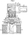
- the valve combination shown in Fig. 1 consists of a as Membrane valve trained main valve 10, a cable head 12 with pilot valve 14 integrated therein, which acts as a small valve is formed, and a fluidic coupling 16, which Main valve 10 connects to the cable head 12.
- the cable head 12 is equipped with an electrical quick connector 18.
- the Main valve 10 has two coaxial media connections 10a, 10b and one laterally arranged valve chamber with a membrane 20 on its outer circumference between a side flange of the main valve 10 and a valve cover 22 is clamped.
- the membrane 20 cooperates an annular sealing seat 24, against which they are by a Compression spring 26 is loaded.
- first channel 28 from the media connection 10a through the valve cover 22 led to a connection flange 30 formed thereon.
- a second channel 32 is from the media connection 10b through the valve cover 22 led to the connecting flange 30.
- a third channel 34 is of that Space behind the membrane 20 led to the connecting flange 30.
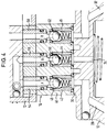
- the clutch 16 shown enlarged in FIG. 4 consists of a on the connecting flange 30 placed intermediate plate 40 with three through connection bores 42, 44, 46 is provided with align the mouths of channels 28, 32 and 34.
- On the website of the connecting flange 30 is each end of the connecting bore 42, 44, 46 sealed to the flange 30 by an annular seal.
- On the Side of the connecting flange 30 in each connection bore 42, 44, 46 Check valve used, the one spring-loaded against an annular seal Ball 48, 50, 52 has.
- On the side of the cable head 12 is in the ends of the connection bores 42, 44, 46 each with a Ring seal provided pipe nipple 54, 56, 58 used sealing.
- the pilot valve 14 is a conventional 3/2-way valve.
- a Such valve has relatively sensitive due to the miniature design electrical leads 62 (Fig. 2). These are inside the Cable head 12 with the electrical quick connector 18 connected and therefore well protected. Since the pilot valve 14 as conventional 3/2-way miniature valve can be formed, superfluous get a detailed description.
- the cable head 12 is detached from the main valve 10 shown.
- the pilot valve 14 can be a direct acting Small valve can be used.
- the fluid ones Connections P A R led out into which the pipe nipples 54, 56, 58 can be used.
- the cable head 12 can also without it Pipe nipple with its fluidic connection surface suitable for one trained counter flange are placed.
- connection configurations are the fluidic coupling 16 the same on both sides. With different Connection configurations between cable head 12 and main valve 10 can be adjusted via the fluidic coupling 16.
- the main valve 10 designed as a diaphragm valve is insensitive against deposits of lime, iron oxide or others in the water dissolved substances.
- the main valve 10 is actuated by means of of the pilot valve 14 via the channels 28, 32 and 34 in a known manner Wise. This results in a low electrical control power also a particularly safe function of the main valve.
- the fluidic coupling 16 with integrated check valves is reduced connecting the pilot valve file 14 to an insertion the pipe nipple into the connection holes, whereupon the screw 60 is tightened to the cable head 12 on the intermediate plate 40 and thus secure at the main valve 10.
- the fluid coupling is mechanical highly resilient.
- the cable head 12 with the Pilot valve 14 can be released from the main valve 10 without Liquid escapes because the check valves close automatically when the pipe nipples come out of the connection holes be pulled out.
- quick connection device 18 enables this easy connection of a cable without tools, at the same time one Strain relief is guaranteed.
Landscapes
- Engineering & Computer Science (AREA)
- General Engineering & Computer Science (AREA)
- Mechanical Engineering (AREA)
- Fluid-Driven Valves (AREA)
- Valve Housings (AREA)
- Magnetically Actuated Valves (AREA)
- Compressor (AREA)
- Superconductors And Manufacturing Methods Therefor (AREA)
Applications Claiming Priority (2)
| Application Number | Priority Date | Filing Date | Title |
|---|---|---|---|
| DE29710023U | 1997-06-09 | ||
| DE29710023 | 1997-06-09 |
Publications (3)
| Publication Number | Publication Date |
|---|---|
| EP0884513A2 true EP0884513A2 (fr) | 1998-12-16 |
| EP0884513A3 EP0884513A3 (fr) | 1999-03-24 |
| EP0884513B1 EP0884513B1 (fr) | 2003-08-20 |
Family
ID=8041368
Family Applications (1)
| Application Number | Title | Priority Date | Filing Date |
|---|---|---|---|
| EP19980110498 Expired - Lifetime EP0884513B1 (fr) | 1997-06-09 | 1998-06-09 | Combinaison de soupape |
Country Status (4)
| Country | Link |
|---|---|
| US (1) | US5975486A (fr) |
| EP (1) | EP0884513B1 (fr) |
| AT (1) | ATE247791T1 (fr) |
| DE (1) | DE59809324D1 (fr) |
Families Citing this family (8)
| Publication number | Priority date | Publication date | Assignee | Title |
|---|---|---|---|---|
| US6394412B2 (en) * | 1993-04-02 | 2002-05-28 | Netafim (A.C.S.) Ltd. | Controlled valve |
| US6328275B1 (en) * | 2000-02-04 | 2001-12-11 | Husco International, Inc. | Bidirectional pilot operated control valve |
| US7156121B2 (en) * | 2003-12-11 | 2007-01-02 | Cox Christopher L | Valve position monitor and method of use |
| US7246787B2 (en) * | 2003-12-19 | 2007-07-24 | Kumar Viraraghavan S | Solenoid valve assembly |
| US7922149B2 (en) * | 2004-07-29 | 2011-04-12 | Siemens Industry Inc. | Damper actuator assembly |
| CN101943188B (zh) * | 2010-04-29 | 2013-08-21 | 上海人豪液压技术有限公司 | 采用组合式法兰控制盖板的紧凑型二通插装阀 |
| JP6209139B2 (ja) * | 2014-08-05 | 2017-10-04 | Ckd株式会社 | パイロット式電磁弁 |
| JP6216738B2 (ja) * | 2015-05-26 | 2017-10-18 | Ckd株式会社 | パイロット式電磁弁 |
Family Cites Families (19)
| Publication number | Priority date | Publication date | Assignee | Title |
|---|---|---|---|---|
| US2412490A (en) * | 1944-04-26 | 1946-12-10 | Gen Controls Co | Fluid control valve |
| US2893680A (en) * | 1955-01-10 | 1959-07-07 | Phillips Petroleum Co | Valve |
| DE1085000B (de) * | 1957-06-18 | 1960-07-07 | Concordia Maschinen U Elek Zit | Absperrventil fuer wechselnde Durchflussrichtungen |
| DE1161099B (de) * | 1958-12-13 | 1964-01-09 | Concordia Maschinen Und Elek Z | Vierwegeventil |
| US3145967A (en) * | 1962-04-27 | 1964-08-25 | Lawrence H Gardner | Elastic sleeve valve |
| US3265352A (en) * | 1963-09-25 | 1966-08-09 | Westinghouse Air Brake Co | Valve assembly with liquid-seal electrical plug connection |
| US3477466A (en) * | 1967-04-03 | 1969-11-11 | Lewis D Sturm | Elevator fluid control valve mechanism |
| CH498324A (de) * | 1968-09-05 | 1970-10-31 | Biolog Verfahrenstechnik Ag F | Elektromagnetisches Einspritzventil |
| US3913884A (en) * | 1973-07-09 | 1975-10-21 | Automatic Switch Co | Variable bleed valve |
| NO140919C (no) * | 1978-04-17 | 1979-12-12 | Helge Dybvig | Anordning ved drivstoffsystem, saerlig for baater |
| DE3514900A1 (de) * | 1985-04-25 | 1986-11-06 | Krytem GmbH, 4156 Willich | Absperrorgan fuer vorzugsweise tiefgekuehlte gase fuehrende leitungen, insbesondere ventil |
| JPS6241482A (ja) * | 1985-08-15 | 1987-02-23 | Smc Corp | パイロツト式2ポ−ト電磁弁 |
| DE3717341A1 (de) * | 1987-05-22 | 1988-12-08 | Daimler Benz Ag | Ventilanordnung mit hauptschaltventil und vorsteuerventil |
| US4981280A (en) * | 1989-04-27 | 1991-01-01 | The Aro Corporation | Solenoid actuated fluid valve |
| US5074524A (en) * | 1990-10-16 | 1991-12-24 | Bridge Products, Inc. | Quick disconnect coupler |
| CN1026256C (zh) * | 1991-07-02 | 1994-10-19 | 浙江瑞安永久机电研究所 | 隔离自控阀 |
| WO1997018397A1 (fr) * | 1995-11-13 | 1997-05-22 | Wilkerson Corporation | Soupape d'alimentation et d'echappement pour demarrage lent |
| US5794651A (en) * | 1996-03-13 | 1998-08-18 | General Hydraulics Corporation | Valve adaptor cap |
| FR2752901B1 (fr) * | 1996-08-28 | 1998-10-09 | Bayard | Electrovanne de commande d'une installation de disribution d'eau |
-
1998
- 1998-06-09 DE DE59809324T patent/DE59809324D1/de not_active Expired - Fee Related
- 1998-06-09 AT AT98110498T patent/ATE247791T1/de not_active IP Right Cessation
- 1998-06-09 US US09/093,792 patent/US5975486A/en not_active Expired - Fee Related
- 1998-06-09 EP EP19980110498 patent/EP0884513B1/fr not_active Expired - Lifetime
Also Published As
| Publication number | Publication date |
|---|---|
| ATE247791T1 (de) | 2003-09-15 |
| DE59809324D1 (de) | 2003-09-25 |
| US5975486A (en) | 1999-11-02 |
| EP0884513B1 (fr) | 2003-08-20 |
| EP0884513A3 (fr) | 1999-03-24 |
Similar Documents
| Publication | Publication Date | Title |
|---|---|---|
| DE4101001C2 (de) | Kupplungsteilvorrichtung mit Druckreduzierelementen | |
| EP0271765B1 (fr) | Soupape commandée par le fluide propre, déclenchable notamment par un électroaimant pilote | |
| DE69713361T2 (de) | Schnellkupplung mit sicherheitsventil und druckentlastungsventil | |
| EP0038470B1 (fr) | Eléments de connexion s'enfonçant l'un dans l'autre pour conduites de fluides sous pression dans un aquarium | |
| AT400748B (de) | Patronenventil | |
| DE3829242C2 (de) | Selbstspülende hydraulische Kupplung und Verfahren zum Spülen einer Hydraulikleitung mit einer solchen hydraulischen Kupplung | |
| EP0038056A2 (fr) | Accouplement à action rapide pour tuyaux souples ou analogues | |
| DE2061821A1 (de) | Vorrichtung zum Anschluß hydraulischer Gerate | |
| DE102013111456B4 (de) | Abschaltventil | |
| EP1357325A2 (fr) | Raccord rapide | |
| DE10018364A1 (de) | Hydraulische Unterwasserkupplung mit verlängertem Sondenabschnitt | |
| DE102014106940B4 (de) | Elektromagnetisch betätigbares Hochdruckgasventil | |
| DE10123498B4 (de) | Hydraulisches Unterwasser-Kupplungsteil mit Primär- und Sekundärtellerventil | |
| EP0884513B1 (fr) | Combinaison de soupape | |
| EP1287590A1 (fr) | Connecteur enfichable a compensation de pression | |
| EP0754899B1 (fr) | Soupape sphérique avec raccord rapide | |
| DE10121294A1 (de) | Druckausgeglichene hydraulische Unterwasserkupplung | |
| EP0005197A1 (fr) | Dispositif de sécurité en cas de rupture du tuyau, placé entre une conduite sous pression et le raccordement à un appareil | |
| DE1650143A1 (de) | Stroemungsmittelkupplung | |
| EP0065556A1 (fr) | Dispositif d'accouplement pour raccorder deux sections de conduite pour matieres fluides | |
| DE69715199T2 (de) | Ventilanordnung für Heizsysteme und Wasserheizgeräte und Verfahren zu ihrer Herstellung | |
| EP1893459A1 (fr) | Vis d'evacuation d'air a soupape de non-retour | |
| DE102018124864B4 (de) | Hochdruck-Sicherheitsventil | |
| DE202011004778U1 (de) | Kupplungsteil einer Druckmittel-Leitungskupplung | |
| DD253751A5 (de) | Ferkeltraenkebecken |
Legal Events
| Date | Code | Title | Description |
|---|---|---|---|
| PUAI | Public reference made under article 153(3) epc to a published international application that has entered the european phase |
Free format text: ORIGINAL CODE: 0009012 |
|
| AK | Designated contracting states |
Kind code of ref document: A2 Designated state(s): AT CH DE FR GB IT LI |
|
| AX | Request for extension of the european patent |
Free format text: AL;LT;LV;MK;RO;SI |
|
| PUAL | Search report despatched |
Free format text: ORIGINAL CODE: 0009013 |
|
| AK | Designated contracting states |
Kind code of ref document: A3 Designated state(s): AT BE CH CY DE DK ES FI FR GB GR IE IT LI LU MC NL PT SE |
|
| AX | Request for extension of the european patent |
Free format text: AL;LT;LV;MK;RO;SI |
|
| 17P | Request for examination filed |
Effective date: 19990506 |
|
| AKX | Designation fees paid |
Free format text: AT CH DE FR GB IT LI |
|
| 17Q | First examination report despatched |
Effective date: 20020502 |
|
| GRAH | Despatch of communication of intention to grant a patent |
Free format text: ORIGINAL CODE: EPIDOS IGRA |
|
| GRAS | Grant fee paid |
Free format text: ORIGINAL CODE: EPIDOSNIGR3 |
|
| GRAA | (expected) grant |
Free format text: ORIGINAL CODE: 0009210 |
|
| AK | Designated contracting states |
Designated state(s): AT CH DE FR GB IT LI |
|
| REG | Reference to a national code |
Ref country code: GB Ref legal event code: FG4D Free format text: NOT ENGLISH |
|
| REG | Reference to a national code |
Ref country code: CH Ref legal event code: NV Representative=s name: TROESCH SCHEIDEGGER WERNER AG Ref country code: CH Ref legal event code: EP |
|
| REF | Corresponds to: |
Ref document number: 59809324 Country of ref document: DE Date of ref document: 20030925 Kind code of ref document: P |
|
| GBT | Gb: translation of ep patent filed (gb section 77(6)(a)/1977) |
Effective date: 20031119 |
|
| ET | Fr: translation filed | ||
| PGFP | Annual fee paid to national office [announced via postgrant information from national office to epo] |
Ref country code: DE Payment date: 20040602 Year of fee payment: 7 |
|
| PGFP | Annual fee paid to national office [announced via postgrant information from national office to epo] |
Ref country code: FR Payment date: 20040608 Year of fee payment: 7 |
|
| PGFP | Annual fee paid to national office [announced via postgrant information from national office to epo] |
Ref country code: GB Payment date: 20040609 Year of fee payment: 7 |
|
| PGFP | Annual fee paid to national office [announced via postgrant information from national office to epo] |
Ref country code: AT Payment date: 20040611 Year of fee payment: 7 |
|
| PGFP | Annual fee paid to national office [announced via postgrant information from national office to epo] |
Ref country code: CH Payment date: 20040616 Year of fee payment: 7 |
|
| PLBE | No opposition filed within time limit |
Free format text: ORIGINAL CODE: 0009261 |
|
| STAA | Information on the status of an ep patent application or granted ep patent |
Free format text: STATUS: NO OPPOSITION FILED WITHIN TIME LIMIT |
|
| 26N | No opposition filed |
Effective date: 20040524 |
|
| PG25 | Lapsed in a contracting state [announced via postgrant information from national office to epo] |
Ref country code: IT Free format text: LAPSE BECAUSE OF NON-PAYMENT OF DUE FEES Effective date: 20050609 Ref country code: AT Free format text: LAPSE BECAUSE OF NON-PAYMENT OF DUE FEES Effective date: 20050609 |
|
| PG25 | Lapsed in a contracting state [announced via postgrant information from national office to epo] |
Ref country code: LI Free format text: LAPSE BECAUSE OF NON-PAYMENT OF DUE FEES Effective date: 20050630 Ref country code: CH Free format text: LAPSE BECAUSE OF NON-PAYMENT OF DUE FEES Effective date: 20050630 |
|
| PG25 | Lapsed in a contracting state [announced via postgrant information from national office to epo] |
Ref country code: DE Free format text: LAPSE BECAUSE OF NON-PAYMENT OF DUE FEES Effective date: 20060103 |
|
| REG | Reference to a national code |
Ref country code: CH Ref legal event code: PL |
|
| PG25 | Lapsed in a contracting state [announced via postgrant information from national office to epo] |
Ref country code: FR Free format text: LAPSE BECAUSE OF NON-PAYMENT OF DUE FEES Effective date: 20060228 |
|
| GBPC | Gb: european patent ceased through non-payment of renewal fee |
Effective date: 20050609 |
|
| REG | Reference to a national code |
Ref country code: FR Ref legal event code: ST Effective date: 20060228 |