EP0884527A2 - Brûleur à gaz à faible taux de NOx - Google Patents
Brûleur à gaz à faible taux de NOx Download PDFInfo
- Publication number
- EP0884527A2 EP0884527A2 EP98110455A EP98110455A EP0884527A2 EP 0884527 A2 EP0884527 A2 EP 0884527A2 EP 98110455 A EP98110455 A EP 98110455A EP 98110455 A EP98110455 A EP 98110455A EP 0884527 A2 EP0884527 A2 EP 0884527A2
- Authority
- EP
- European Patent Office
- Prior art keywords
- burner
- periphery
- ports
- peripheral edge
- upper plate
- Prior art date
- Legal status (The legal status is an assumption and is not a legal conclusion. Google has not performed a legal analysis and makes no representation as to the accuracy of the status listed.)
- Withdrawn
Links
Images

Classifications
-
- F—MECHANICAL ENGINEERING; LIGHTING; HEATING; WEAPONS; BLASTING
- F23—COMBUSTION APPARATUS; COMBUSTION PROCESSES
- F23D—BURNERS
- F23D14/00—Burners for combustion of a gas, e.g. of a gas stored under pressure as a liquid
- F23D14/46—Details
- F23D14/70—Baffles or like flow-disturbing devices
-
- F—MECHANICAL ENGINEERING; LIGHTING; HEATING; WEAPONS; BLASTING
- F23—COMBUSTION APPARATUS; COMBUSTION PROCESSES
- F23D—BURNERS
- F23D14/00—Burners for combustion of a gas, e.g. of a gas stored under pressure as a liquid
- F23D14/02—Premix gas burners, i.e. in which gaseous fuel is mixed with combustion air upstream of the combustion zone
- F23D14/04—Premix gas burners, i.e. in which gaseous fuel is mixed with combustion air upstream of the combustion zone induction type, e.g. Bunsen burner
- F23D14/06—Premix gas burners, i.e. in which gaseous fuel is mixed with combustion air upstream of the combustion zone induction type, e.g. Bunsen burner with radial outlets at the burner head
-
- F—MECHANICAL ENGINEERING; LIGHTING; HEATING; WEAPONS; BLASTING
- F23—COMBUSTION APPARATUS; COMBUSTION PROCESSES
- F23C—METHODS OR APPARATUS FOR COMBUSTION USING FLUID FUEL OR SOLID FUEL SUSPENDED IN A CARRIER GAS OR AIR
- F23C2203/00—Flame cooling methods otherwise than by staging or recirculation
- F23C2203/20—Flame cooling methods otherwise than by staging or recirculation using heat absorbing device in flame
-
- F—MECHANICAL ENGINEERING; LIGHTING; HEATING; WEAPONS; BLASTING
- F23—COMBUSTION APPARATUS; COMBUSTION PROCESSES
- F23D—BURNERS
- F23D2213/00—Burner manufacture specifications
Definitions
- This invention relates to gas burners and gas burner head configurations. More specifically, the invention relates to gas burners of the type typically used in water heaters.
- Gas burners for domestic water heaters typically utilize burner heads formed from two concave halves which are secured together. See, for example, U.S. Patents 3,992,137; 4,372,290 or 5,335,646. Such burners generally are supported by a bracket attached to the bottom concave portion which includes a central opening for inflow of an air-gas mixture. A plurality of burner ports are disposed in a spaced apart circular array around the periphery of the burner so that a ring of flames issues radially outwardly therefrom for heating the bottom wall of a water tank.
- the combustion products of the heating process ideally would consist of carbon dioxide and water. However, if incomplete combustion occurs, carbon monoxide may be produced. Also, at elevated temperatures, a small amount of undesirable nitrogen oxide varieties such as nitric oxide (NO) and nitrogen dioxide (NO 2 ), generally collectively referred to as NO x . Nitrogen dioxide, in particular, is objectionable because it is a brownish colored toxic gas which can support combustion. It is desirable and mandated by law that the NOx species be converted as efficiently as possible to gaseous nitrogen or other nontoxic forms. It has thus remained an ongoing goal of the industry and, in many places mandated by law to produce burners achieving higher combustion efficiency as well as minimization of NO x content of the exhaust gases.
- a gas burner of this invention adapted to discharge said fuel at its the periphery for combustion, includes upper, and lower concave plates secured together to define a chamber and an outer periphery having a plurality of burner ports.
- the peripheral edge of at least one or the other of the top or bottom burner plates extends radially outwardly from the central axis a distance beyond the location of the burner ports and into the path of burning gases issuing radially outwardly from the ports, whereby the temperature of said burning gases is reduced.
- the upper plate having a periphery extending radially at least as far as the lower plate.
- the periphery of the upper plate is downwardly angled, preferably more steeply than the periphery of the lower plate.
- the periphery of the upper plate extends downwardly to an elevation below the elevation of the upper edges of the burner ports, so that gases emerging radially outwardly from the ports are caused to impinge against the upper plate periphery, thus cooling the gases and thereby reducing the NO x content of the combustion gases.
- Water heater 10 incorporating a burner 15 of this invention.
- Water heater 10 includes a water-containing tank 12 provided with a bottom wall 14 and a centrally located exhaust flue 16. Exhaust flue 16 is vented through a fitting 18 to a suitable flue, all of conventional design.
- Commercially available temperature control devices 20, including suitable conventional thermostats, thermocouples and switches are also provided as is known in the art.
- a pilot light providing a pilot flame 24 for ignition of the burner 15, together with suitable associated controls of conventional design.
- Tank 12 is provided with a double walled configuration including suitable insulation 18.
- Burner 15 includes a mounting bracket 26 fixed to its lower surface in accordance with known design.
- a gas conduit 20 is attached to a source of fuel such as a natural gas pipeline.
- the tank of water heater 10 is also provided with intake pipes for inflow of cold water and outflow pipe connected to a commercial or domestic water system.
- Gas conduit 28 is terminated by a gas discharge nozzle 29 which is centrally axially aligned with burner 15.
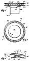
- Burner 15 includes top and bottom plates 30 and 32, respectively, each of which are preferably concavely shaped and formed of one piece.
- Lower plate 32 has a central opening 34 for receiving an inflow of gas from nozzle 29.
- Bottom plate 32 is downwardly concavely formed, as best seen in Figures 3 and 5.
- Plates 30 and 32 together form a chamber 36 which receives the flow of gas.
- Plates 30 and 32 are formed with a plurality of flutes 38 and 40 around their respective peripheries. The flutes 38 and 40 are connected together by means of a rivet 41 as seen in Figure 5, or, alternatively by means of spot welding.
- Angle 48 is preferably about 27° so that its peripheral edge 46 extends into the flow path of the flaming gases at a location where they are exiting ports 42 in a radial direction.
- the fluted portions 38 and 40 define the ports 42 with the flutes 38 and 40 preferably being secured together by small rivets.
- both the top plate 30 and the bottom plate 32 are circular in configuration.
- the burner openings 42 defined by the flutes 38, 40 preferably extend around the entire periphery of the burner 15.
- gas for example propane or natural gas
- gas supply conduit 28 supplied by gas supply conduit 28
- combustion air is provided by the ambient atmosphere.
- the gas flowing through opening 34 flows upwardly and impinges against the inner surface of the concavely depressed portion 44 of upper plate 30. Thereafter, the gas flows uniformly radially outward in all directions toward, and out through, the plurality of burner ports 42.
- the periphery 46 of upper plate 30 is angled downwardly at an angle 48, preferably about 27°, as best seen in Figure 5.
- Peripheral edge 50 of lower plate 32 extends at a shallower angle, preferably approximately 15° from the horizontal. It will thus be noted that, in the illustrated preferred embodiment, the peripheral edges 46 and 50 converge toward each other.
- the upper plate 30 is formed all of one piece and is of a greater diameter than the lower plate 50. It will also be noted, for example from Figure 3, that the periphery 46 of upper plate 30 extends downwardly a sufficient amount to be positioned in front of the upper edges of each of the openings 42 which form the gas burner ports. Thus, the burning gases exiting the ports 42 are caused to impinge while they are traveling radially outwardly from the burner ports, against the peripheral edge 46 of plate 30. This impingement has been found to beneficially lower the temperature of the burning air-gas mixture exiting the ports, which is believed to be important in the reduction of NO x content of the resultant combustion products.
Landscapes
- Engineering & Computer Science (AREA)
- Chemical & Material Sciences (AREA)
- Combustion & Propulsion (AREA)
- Mechanical Engineering (AREA)
- General Engineering & Computer Science (AREA)
- Gas Burners (AREA)
- Combustion Of Fluid Fuel (AREA)
- Pre-Mixing And Non-Premixing Gas Burner (AREA)
Applications Claiming Priority (2)
| Application Number | Priority Date | Filing Date | Title |
|---|---|---|---|
| US871242 | 1997-06-09 | ||
| US08/871,242 US5913675A (en) | 1997-06-09 | 1997-06-09 | Low NOx gas burner |
Publications (2)
| Publication Number | Publication Date |
|---|---|
| EP0884527A2 true EP0884527A2 (fr) | 1998-12-16 |
| EP0884527A3 EP0884527A3 (fr) | 1999-09-08 |
Family
ID=25357008
Family Applications (1)
| Application Number | Title | Priority Date | Filing Date |
|---|---|---|---|
| EP98110455A Withdrawn EP0884527A3 (fr) | 1997-06-09 | 1998-06-08 | Brûleur à gaz à faible taux de NOx |
Country Status (5)
| Country | Link |
|---|---|
| US (2) | US5913675A (fr) |
| EP (1) | EP0884527A3 (fr) |
| JP (1) | JPH1172209A (fr) |
| AU (1) | AU6903598A (fr) |
| CA (1) | CA2238793A1 (fr) |
Families Citing this family (22)
| Publication number | Priority date | Publication date | Assignee | Title |
|---|---|---|---|---|
| US6267586B1 (en) | 2000-05-05 | 2001-07-31 | Beckett Gas, Inc. | Low NOx burner |
| US7121097B2 (en) | 2001-01-16 | 2006-10-17 | Catalytica Energy Systems, Inc. | Control strategy for flexible catalytic combustion system |
| US6718772B2 (en) | 2000-10-27 | 2004-04-13 | Catalytica Energy Systems, Inc. | Method of thermal NOx reduction in catalytic combustion systems |
| US6796129B2 (en) | 2001-08-29 | 2004-09-28 | Catalytica Energy Systems, Inc. | Design and control strategy for catalytic combustion system with a wide operating range |
| US20040255588A1 (en) * | 2002-12-11 | 2004-12-23 | Kare Lundberg | Catalytic preburner and associated methods of operation |
| BRPI0406806A (pt) * | 2003-01-17 | 2005-12-27 | Catalytica Energy Sys Inc | Sistema e método de controle dinâmico para multicombustor catalìtico para motor de turbina a gás |
| WO2005026675A2 (fr) * | 2003-09-05 | 2005-03-24 | Catalytica Energy Systems, Inc. | Detection de surchauffe d'un module catalyseur et procedes de reaction |
| MX2007009720A (es) * | 2005-02-11 | 2007-09-26 | Robertshaw Controls Co | Quemador de piloto con bajo contenido de nox y metodo asociado de uso. |
| US20140178548A1 (en) * | 2012-11-14 | 2014-06-26 | Biolite Llc | Efficiency pot and kettle for use with cooking stoves |
| US9038576B2 (en) | 2013-05-22 | 2015-05-26 | Plum Combustion, Inc. | Ultra low NOx burner using distributed direct fuel injection |
| USD787041S1 (en) * | 2015-09-17 | 2017-05-16 | Whirlpool Corporation | Gas burner |
| US10837651B2 (en) | 2015-09-24 | 2020-11-17 | Whirlpool Corporation | Oven cavity connector for operating power accessory trays for cooking appliance |
| US11777190B2 (en) | 2015-12-29 | 2023-10-03 | Whirlpool Corporation | Appliance including an antenna using a portion of appliance as a ground plane |
| US10145568B2 (en) | 2016-06-27 | 2018-12-04 | Whirlpool Corporation | High efficiency high power inner flame burner |
| US10551056B2 (en) | 2017-02-23 | 2020-02-04 | Whirlpool Corporation | Burner base |
| US10451290B2 (en) | 2017-03-07 | 2019-10-22 | Whirlpool Corporation | Forced convection steam assembly |
| US10660162B2 (en) | 2017-03-16 | 2020-05-19 | Whirlpool Corporation | Power delivery system for an induction cooktop with multi-output inverters |
| CN109990286B (zh) * | 2017-12-29 | 2024-02-23 | 芜湖美的厨卫电器制造有限公司 | 燃烧器及燃气热水器 |
| US10627116B2 (en) | 2018-06-26 | 2020-04-21 | Whirlpool Corporation | Ventilation system for cooking appliance |
| US10619862B2 (en) | 2018-06-28 | 2020-04-14 | Whirlpool Corporation | Frontal cooling towers for a ventilation system of a cooking appliance |
| US10837652B2 (en) | 2018-07-18 | 2020-11-17 | Whirlpool Corporation | Appliance secondary door |
| CN110173887B (zh) * | 2019-06-17 | 2024-03-12 | 景洪 | 一种预混低氮燃气容积式热水器及其控制方法 |
Citations (3)
| Publication number | Priority date | Publication date | Assignee | Title |
|---|---|---|---|---|
| US3992137A (en) | 1975-02-21 | 1976-11-16 | A. O. Smith Corporation | Gas burner |
| US4372290A (en) | 1980-09-05 | 1983-02-08 | Emerson Electric Co. | Gas burner head with means for evacuating trapped water condensate |
| US5335646A (en) | 1993-08-30 | 1994-08-09 | Robertshaw Controls Company | Water heater, a burner unit therefor and methods of making the same |
Family Cites Families (7)
| Publication number | Priority date | Publication date | Assignee | Title |
|---|---|---|---|---|
| US1933790A (en) * | 1931-10-16 | 1933-11-07 | Francis G Crone | Gas burner |
| US4525141A (en) * | 1983-07-11 | 1985-06-25 | Gas Research Institute | Regulation of blue flame combustion emissions |
| US4629415A (en) * | 1983-07-11 | 1986-12-16 | Gas Research Institute | Flame insert |
| US4951614A (en) * | 1988-03-21 | 1990-08-28 | A. O. Smith Corp. | Water heater construction |
| DE9016930U1 (de) * | 1990-12-14 | 1991-03-28 | Bosch-Siemens Hausgeräte GmbH, 8000 München | Vorrichtung für einen Kochstellenbrenner |
| US5448969A (en) * | 1994-03-23 | 1995-09-12 | Bowles Fluidics Corporation | Fluidic burner |
| US5826569A (en) * | 1996-10-04 | 1998-10-27 | American Water Heater Company | Low NOx water heater with finned burner |
-
1997
- 1997-06-09 US US08/871,242 patent/US5913675A/en not_active Expired - Lifetime
-
1998
- 1998-05-27 CA CA002238793A patent/CA2238793A1/fr not_active Abandoned
- 1998-05-28 AU AU69035/98A patent/AU6903598A/en not_active Abandoned
- 1998-06-04 JP JP10156145A patent/JPH1172209A/ja active Pending
- 1998-06-08 EP EP98110455A patent/EP0884527A3/fr not_active Withdrawn
- 1998-09-24 US US09/159,449 patent/US5988116A/en not_active Expired - Lifetime
Patent Citations (3)
| Publication number | Priority date | Publication date | Assignee | Title |
|---|---|---|---|---|
| US3992137A (en) | 1975-02-21 | 1976-11-16 | A. O. Smith Corporation | Gas burner |
| US4372290A (en) | 1980-09-05 | 1983-02-08 | Emerson Electric Co. | Gas burner head with means for evacuating trapped water condensate |
| US5335646A (en) | 1993-08-30 | 1994-08-09 | Robertshaw Controls Company | Water heater, a burner unit therefor and methods of making the same |
Also Published As
| Publication number | Publication date |
|---|---|
| CA2238793A1 (fr) | 1998-12-09 |
| EP0884527A3 (fr) | 1999-09-08 |
| US5988116A (en) | 1999-11-23 |
| US5913675A (en) | 1999-06-22 |
| JPH1172209A (ja) | 1999-03-16 |
| AU6903598A (en) | 1998-12-10 |
Similar Documents
| Publication | Publication Date | Title |
|---|---|---|
| US5913675A (en) | Low NOx gas burner | |
| US4510890A (en) | Infrared water heater | |
| CA2130948C (fr) | Chauffe-eau a bruleur integre | |
| US5240411A (en) | Atmospheric gas burner assembly | |
| CA2130964C (fr) | Chauffe-eau muni d'un bruleur en ceramique a faible degagement d'oxydes d'azote | |
| CA2021763C (fr) | Bruleur a melange etudie du gaz de combustion, pour systeme de chauffage a ventilation forcee, utilisant une chambre de combustion fermee | |
| US5879154A (en) | Flame spreader-type fuel burner with lowered NOx emissions | |
| EP0854322B1 (fr) | Brûleur à gaz prémélangé | |
| US6725811B1 (en) | Water heater with low NOx fiber matrix burner | |
| US7690375B2 (en) | Deep fat tube fryer burner assembly | |
| EP0769120B1 (fr) | Chambre de melange d'un bruleur | |
| US20030077551A1 (en) | Micro inshot burner | |
| US10006628B2 (en) | Low NOx gas burners with carryover ignition | |
| US6485294B2 (en) | NOx reduction device | |
| US7052273B2 (en) | Premixed fuel burner assembly | |
| US5293860A (en) | Standing pilot furnace with vented vestibule | |
| US6736634B2 (en) | NOx reduction with a combination of radiation baffle and catalytic device | |
| US4919120A (en) | Radiant-type heater | |
| USRE37128E1 (en) | Standing pilot furnace with vented vestibule | |
| US2855919A (en) | Heating units | |
| JP2000193211A (ja) | コンロ用バ―ナ | |
| US6267586B1 (en) | Low NOx burner | |
| US4674974A (en) | Pot burner for liquid fuel | |
| CA2399407A1 (fr) | Chauffe-eau a faible emission de nox muni d'un dispositif de protection contre les vapeurs inflammables | |
| US4846679A (en) | Flueless, low NOx, low CO space heater |
Legal Events
| Date | Code | Title | Description |
|---|---|---|---|
| PUAI | Public reference made under article 153(3) epc to a published international application that has entered the european phase |
Free format text: ORIGINAL CODE: 0009012 |
|
| AK | Designated contracting states |
Kind code of ref document: A2 Designated state(s): DE FR GB IT |
|
| AX | Request for extension of the european patent |
Free format text: AL;LT;LV;MK;RO;SI |
|
| RIN1 | Information on inventor provided before grant (corrected) |
Inventor name: PRYOR, WILLIAM M. Inventor name: CARLTON, CLIFFORD Inventor name: DONASTORG, HECTOR J. Inventor name: VAGO, OTTO Z. |
|
| PUAL | Search report despatched |
Free format text: ORIGINAL CODE: 0009013 |
|
| AK | Designated contracting states |
Kind code of ref document: A3 Designated state(s): AT BE CH CY DE DK ES FI FR GB GR IE IT LI LU MC NL PT SE |
|
| AX | Request for extension of the european patent |
Free format text: AL;LT;LV;MK;RO;SI |
|
| 17P | Request for examination filed |
Effective date: 19991027 |
|
| AKX | Designation fees paid |
Free format text: DE FR GB IT |
|
| 17Q | First examination report despatched |
Effective date: 20010814 |
|
| STAA | Information on the status of an ep patent application or granted ep patent |
Free format text: STATUS: THE APPLICATION IS DEEMED TO BE WITHDRAWN |
|
| 18D | Application deemed to be withdrawn |
Effective date: 20020425 |