EP0884546A2 - Vorrichtung zur Verteilung und/oder Schleusung eines heissen mehlförmigen Gutes - Google Patents
Vorrichtung zur Verteilung und/oder Schleusung eines heissen mehlförmigen Gutes Download PDFInfo
- Publication number
- EP0884546A2 EP0884546A2 EP98108587A EP98108587A EP0884546A2 EP 0884546 A2 EP0884546 A2 EP 0884546A2 EP 98108587 A EP98108587 A EP 98108587A EP 98108587 A EP98108587 A EP 98108587A EP 0884546 A2 EP0884546 A2 EP 0884546A2
- Authority
- EP
- European Patent Office
- Prior art keywords
- flap
- hot
- cooling medium
- hollow body
- slide
- Prior art date
- Legal status (The legal status is an assumption and is not a legal conclusion. Google has not performed a legal analysis and makes no representation as to the accuracy of the status listed.)
- Granted
Links
Images

Classifications
-
- F—MECHANICAL ENGINEERING; LIGHTING; HEATING; WEAPONS; BLASTING
- F27—FURNACES; KILNS; OVENS; RETORTS
- F27B—FURNACES, KILNS, OVENS OR RETORTS IN GENERAL; OPEN SINTERING OR LIKE APPARATUS
- F27B7/00—Rotary-drum furnaces, i.e. horizontal or slightly inclined
- F27B7/20—Details, accessories or equipment specially adapted for rotary-drum furnaces
- F27B7/2016—Arrangements of preheating devices for the charge
- F27B7/2025—Arrangements of preheating devices for the charge consisting of a single string of cyclones
- F27B7/2033—Arrangements of preheating devices for the charge consisting of a single string of cyclones with means for precalcining the raw material
Definitions
- the invention relates to a device for distribution and / or Smuggling a hot flour-like material, especially one hot cement raw meal stream in a plant for the production of Cement clinker made from raw cement meal in a heat exchanger system preheated and fired in a rotary kiln to cement clinker becomes.
- the distribution or conversion of the hot raw meal stream is previously accomplished with a distributor housing on the top the hot flour feed line and on the underside there are two hot flour feed lines are connectable so that the distributor housing from its shape is also referred to as a so-called "downpipe".
- a flap is pivotally arranged in the downpipe through which Swiveling the hot cement raw meal stream, which is a temperature from e.g. Can have 800 to 900 ° C, distributed or converted becomes. It goes without saying that the pivoting flap in particular exposed to high thermochemical and abrasive wear is.
- impact slides which in cement plants cross into one hot gas pipe coming from the rotary kiln and / or from the clinker cooler are installed and have the task of preheated raw cement meal, that is inserted into the hot gas line from the side is to distribute or evenly over the hot gas cross section suspend, are subject to high wear.
- Flap boxes or shuttle locks also double shuttle locks installed, in which one or two weight-loaded swing flaps are integrated, which have the task of the hot gas flow in each case withhold and on the other hand after a certain solid loading by swinging open the flaps the hot raw meal stream to let down through the flour fall pipe. Also these swing flaps are subject to high wear.
- the invention has for its object, in particular for cement plant construction for the distribution and / or smuggling of a hot flour-like Gutstromes to create a device, one internals subject to high wear, in particular the actuator, have a long service life.
- Characteristic of the distribution device according to the invention and / or transporting a hot flour-like material flow with swivel flap / pendulum flap or impact slider is that this organ particularly exposed to wear as a plate-shaped Hollow body through which cooling medium is formed, at least a cooling medium inlet opening and at least one cooling medium outlet opening having.
- a cooling medium is simplicity half of the outside air is used as cooling air by a cooling air fan or starting from a compressed air network connection the plate hollow body is pressed.
- the cooling medium cools the in the Rule made of metallic material hollow body flap or the hollow body impact slide and their surface. Solid caking on the cooled comparatively lightweight Organs according to the invention are avoided. All in all is the lifespan or the lifespan of the invention Hot flour distribution device or hot meal lock very high.
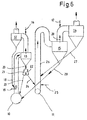
- the two-strand system for the production of cement clinker from raw cement flour 6 shows a left of the exhaust gas of a rotary kiln 10 flowed through strand and a right strand, the of hot radiator exhaust air via a tertiary air line 11 of the not shown Clinker cooler supplied with high-temperature cooler exhaust air becomes.
- Both strands each have cyclone floating gas preheater strands operated by themselves on, each for the sake of simplicity only the bottom two cyclone stages 12, 13 and 14, 15 are drawn are.
- Raw meal quantity can be on the left strand at 16 e.g. approx. 50% Raw flour and on the right strand at 17 also e.g. approx. 50% Quantity of raw flour to be abandoned.
- the Raw meal introduction point in the rotary kiln exhaust gas is located above an impact slide 19, which has the purpose of the introduced Distribute hot flour evenly across the rotary kiln exhaust gas cross-section.
- the flap 22 of the changeover box 21 switched and the hot flour of the left strand is via hot flour line 24 in the calciner 26 equipped with secondary firing 25 of the right strand into which the raw meal from the second lowest cyclone stage 14 of the right strand via line 27 also flows.
- the calcined in the Calinator 26 total cement raw meal in the bottom cyclone 15 of the right strand separated from the hot exhaust gas stream 28 and as high (e.g. 95%) calcined cement raw meal 29 introduced into the rotary kiln 10, in whose sintering zone is fired into cement clinker.
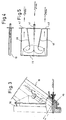
- the hot flour change box or distribution box 21 with the cooled Control flap 22 is drawn out in FIGS. 1 and 2.
- the flap 22, which can be pivoted about its underside, is through which the coolant flows Hollow body formed in the tubular housing 21 is arranged and, depending on the swivel position, the incoming hot meal stream 20 in one and / or other good derivation 23, 24 derives.
- the inside of the Hollow body flap 22 at least one arranged transversely to the flap plane Web 30 built into the one end of the hollow Valve shaft 31 supplied cooling medium, in the embodiment Cooling air, through the flap cavity to the other end of the hollow Valve shaft 31 for the purpose of extending the cooling air dwell time redirects.
- the cooling air conveyed by the cooling air fan 32 becomes inserted into one end of the hollow shaft 31 via a flexible line 33, and the cooling air heated in the flap 22 becomes over the other Blown end of the hollow shaft 31 via line 34 into the environment.
- the pivoting flap 22 is actuated via an adjustment drive 35, e.g. Electric actuator with motor 36 and articulated spindle 37, or via hydraulic swivel cylinders, pneumatic swivel cylinders etc.
- the impact slide 19 of FIG. 6 is drawn out in FIGS. 3 to 5.
- the impact slide is in FIG 19 from the right into rotary kiln exhaust gas riser 38 built-in.
- the hot flour introduced via the flour line 18 becomes in the event of an impact on the impact slide 19 of this evenly distributed the entire cross section of the rotary kiln exhaust gas riser.
- the impact slide 19 is also a hollow body through which cooling air flows formed, in the interior of which at least one transverse to the slide plane arranged web, in the exemplary embodiment according to FIG.
- two webs 39, 40 are installed, which over one the inlet opening 41 arranged on the outer slide face Cooling medium, cooling air again in the exemplary embodiment, for at least one also arranged on the outside of the slide face Coolant outlet opening, according to Figure 5 to the outlet openings Deflect 42 and 43.
- the through the opening 41 in the hollow body impact slide 19 introduced cooling air can high-speed compressed air be from their surroundings after the Injector principle further air volumes in the area in sucks the hollow body and through the hollow body to cool it promotes.
- the service life of the air-cooled impact slide 19 of the figure 3 is also very high.
- the air-cooled impact slide 19 can not only in the calcining zone the cement clinker production line, as shown in the example in FIG. 6, be installed, but also at another point in the cyclone suspended gas heat exchanger system, e.g. in the exhaust pipe between the bottom and the second bottom cyclone etc.
Landscapes
- Engineering & Computer Science (AREA)
- Mechanical Engineering (AREA)
- General Engineering & Computer Science (AREA)
- Furnace Details (AREA)
- Muffle Furnaces And Rotary Kilns (AREA)
- Curing Cements, Concrete, And Artificial Stone (AREA)
Abstract
Description
- Figur 1:
- in Seitenansicht ein hosenrohrförmiges Heißmehlverteilergehäuse mit luftgekühlter verstellbarer Klappe zur Verteilung/Umstellung eines von oben zuströmenden Heißmehlstromes in die eine und/oder andere Ableitung, gesehen in Richtung des Pfeiles I der Figur 2,
- Figur 2:
- die um 90° versetzte andere Seitenansicht auf den Heißmehl-Umstellkasten der Figur 1 mit integrierter luftgekühlter Umstellklappe,
- Figur 3:
- im Vertikalschnitt einen luftgekühlten Prallschieber, eingebaut in eine Drehofenabgassteigleitung unterhalb der Heißmehleinführungsöffnung,
- Figur 4:
- herausgezeichnet etwas vergrößert den Vertikalschnitt durch den luftgekühlten Prallschieber der Figur 3,
- Figur 5:
- die Draufsicht, teilweise im Horizontalschnitt auf den luftgekühlten Prallschieber der Figur 4, und
- Figur 6:
- ausschnittsweise schematisch eine sogenannte Zweistranganlage (Zwillingsanlage) zur Herstellung von Zementklinker aus Zementrohmehl mit integrierter luftgekühlter Heißmehlumstellklappe und mit integriertem luftgekühlten Prallschieber.
Claims (6)
- Vorrichtung zur Verteilung und/oder Schleusung eines heißen mehlförmigen Gutes, insbesondere eines heißen Zementrohmehlstromes in einer Anlage zur Herstellung von Zementklinker aus Zementrohmehl, das in einem Wärmetauschersystem vorerhitzt und in einem Drehrohrofen zu Zementklinker gebrannt wird,
dadurch gekennzeichnet, daß das Stellorgan der Vorrichtung als plattenförmiger kühlmediumdurchströmter Hohlkörper (22, 19) ausgebildet ist, der wenigstens eine Kühlmediumeintrittsöffnung und wenigstens eine Kühlmediumaustrittsöffnung aufweist. - Vorrichtung nach Anspruch 1,
dadurch gekennzeichnet, daß das Stellorgan aus einer Hohlkörper-Klappe (22) besteht, die in einem hosenrohrförmigen Gehäuse (21) mit an der Oberseite angeordneter Gutzuleitungsöffnung (20) und an der Unterseite angeschlossenen zwei Gutableitungen mit einer Welle (31) schwenkbar gelagert ist zur Leitung und/oder Umschaltung des eintretenden Gutstromes in die eine und/oder in die andere Gutableitung (23, 24). - Vorrichtung nach Anspruch 1,
dadurch gekennzeichnet, daß das Stellorgan aus einem HohlkörperPrallschieber (19) besteht, der in eine Heißgassteigleitung (38) im Bereich unterhalb einer Guteintrittsöffnung zwecks Suspendierung bzw. gleichmäßigen Verteilung des eingeführten Gustromes (18) integriert ist. - Vorrichtung nach Anspruch 1,
dadurch gekennzeichnet, daß das Stellorgan aus wenigstens einer gewichtsbelasteten Pendelklappe einer Zementrohmehl-Pendelschleuse besteht. - Vorrichtung nach Anspruch 2 oder 4,
dadurch gekennzeichnet, daß im Inneren der plattenförmigen Hohlkörper-Klappe (22) wenigstens ein quer zur Klappenebene angeordneter Steg (30) eingebaut ist, der das über das eine Ende der hohlen Klappenwelle (31) zugeführte Kühlmedium durch den Klappenhohlraum zum anderen Ende der hohlen Klappenwelle umlenkt. - Vorrichtung nach Anspruch 3,
dadurch gekennzeichnet, daß im Inneren des Hohlkörper-Prallschiebers (19) wenigstens ein quer zur Schieberebene angeordneter Steg (39, 40) eingebaut ist, welcher das über eine an der äußeren Schieberstirnseite angeordnete Eintrittsöffnung (41) zugeführte Kühlmedium zur wenigstens einen ebenfalls an der Schieberstirnseite angeordneten Kühlmedium-Austrittsöffnung (42, 43) umlenkt.
Applications Claiming Priority (4)
| Application Number | Priority Date | Filing Date | Title |
|---|---|---|---|
| DE19720951 | 1997-05-17 | ||
| DE19720951 | 1997-05-17 | ||
| DE19732778 | 1997-07-30 | ||
| DE19732778A DE19732778A1 (de) | 1997-05-17 | 1997-07-30 | Vorrichtung zur Verteilung und/oder Schleusung eines heißen mehlförmigen Gutes |
Publications (3)
| Publication Number | Publication Date |
|---|---|
| EP0884546A2 true EP0884546A2 (de) | 1998-12-16 |
| EP0884546A3 EP0884546A3 (de) | 2000-02-02 |
| EP0884546B1 EP0884546B1 (de) | 2002-08-07 |
Family
ID=26036657
Family Applications (1)
| Application Number | Title | Priority Date | Filing Date |
|---|---|---|---|
| EP98108587A Expired - Lifetime EP0884546B1 (de) | 1997-05-17 | 1998-05-12 | Vorrichtung zur Verteilung und/oder Schleusung eines heissen mehlförmigen Gutes |
Country Status (3)
| Country | Link |
|---|---|
| US (1) | US6000937A (de) |
| EP (1) | EP0884546B1 (de) |
| DK (1) | DK0884546T3 (de) |
Families Citing this family (7)
| Publication number | Priority date | Publication date | Assignee | Title |
|---|---|---|---|---|
| DE10030613A1 (de) | 2000-06-21 | 2002-01-03 | Kloeckner Humboldt Wedag | Anlage zur thermischen Behandlung von mehlförmigen Rohmaterialien |
| US7229281B2 (en) | 2000-09-11 | 2007-06-12 | Cadence Environmental Energy, Inc. | Method of mixing high temperature gases in mineral processing kilns |
| US6672865B2 (en) * | 2000-09-11 | 2004-01-06 | Cadence Enviromental Energy, Inc. | Method of mixing high temperature gases in mineral processing kilns |
| DE10200960A1 (de) | 2002-01-12 | 2003-07-24 | Kloeckner Humboldt Wedag | Vorrichtung zur Schleusung eines heißen mehlförmigen Gutes |
| US7959435B2 (en) * | 2006-01-09 | 2011-06-14 | Cadence Environmental Energy, Inc. | Method and apparatus for reducing NOx emissions in rotary kilns by SNCR |
| WO2019116350A1 (en) | 2017-12-15 | 2019-06-20 | Flsmidth A/S | Cement raw meal separator apparatus and method of using same |
| EP3794294A1 (de) | 2018-05-15 | 2021-03-24 | FLSmidth A/S | Emissionsreduzierungsvorrichtung zur verarbeitung von partikeln und verfahren zu deren verwendung |
Family Cites Families (9)
| Publication number | Priority date | Publication date | Assignee | Title |
|---|---|---|---|---|
| DE931879C (de) * | 1952-10-17 | 1955-08-18 | Ind G M B H | Verteilvorrichtung fuer von einem Fallrohr gabelfoermig abzweigende Rohre fuer Schuettgut |
| US2742328A (en) * | 1953-11-03 | 1956-04-17 | Smidth & Co As F L | Apparatus for feeding pulverulent material |
| FR1254835A (fr) * | 1960-04-25 | 1961-02-24 | Kloeckner Humboldt Deutz Ag | Dispositif pour le chauffage de la poudre de ciment brut |
| DK410780A (da) * | 1979-12-11 | 1981-06-12 | Smidth & Co As F L | Fremgangsmaade og anlaeg til fyring med fast braendsel i forkalcineringszonen paa et ovnanlaeg |
| US4570549A (en) * | 1984-05-17 | 1986-02-18 | Trozzi Norman K | Splitter for use with a coal-fired furnace utilizing a low load burner |
| US4817442A (en) * | 1984-11-07 | 1989-04-04 | Brian Christoperh Coupe | Sample splitter |
| DE3538707A1 (de) * | 1985-10-31 | 1987-05-07 | Kloeckner Humboldt Deutz Ag | Verfahren und vorrichtung zur thermischen behandlung von mehlfoermigen rohmaterialien |
| DK170368B1 (da) * | 1992-08-06 | 1995-08-14 | Smidth & Co As F L | Fremgangsmåde til bortbrænding af affald i et cementovnanlæg, samt anlæg til udøvelse af fremgangsmåden |
| DE4403210B4 (de) * | 1994-02-03 | 2006-05-04 | Khd Humboldt Wedag Gmbh | Gutmengenverteiler |
-
1998
- 1998-05-11 US US09/075,611 patent/US6000937A/en not_active Expired - Fee Related
- 1998-05-12 DK DK98108587T patent/DK0884546T3/da active
- 1998-05-12 EP EP98108587A patent/EP0884546B1/de not_active Expired - Lifetime
Also Published As
| Publication number | Publication date |
|---|---|
| EP0884546B1 (de) | 2002-08-07 |
| EP0884546A3 (de) | 2000-02-02 |
| US6000937A (en) | 1999-12-14 |
| DK0884546T3 (da) | 2002-10-28 |
Similar Documents
| Publication | Publication Date | Title |
|---|---|---|
| DE2343339C3 (de) | Vorrichtung zum Abkühlen von aus einem Drehrohrofen ausgetragenen Klinkerkörnern | |
| DD232539B5 (de) | Rostbodenelement zum Aufbau einer Rostflaeche | |
| EP1922149B1 (de) | Verfahren und vorrichtung zur vermahlung von heissem und feuchtem rohmaterial | |
| DE2420322A1 (de) | Anlage zum brennen von koernigem oder pulverfoermigem material | |
| DE3538707A1 (de) | Verfahren und vorrichtung zur thermischen behandlung von mehlfoermigen rohmaterialien | |
| EP0884546B1 (de) | Vorrichtung zur Verteilung und/oder Schleusung eines heissen mehlförmigen Gutes | |
| EP0553878B1 (de) | Schubrostkühler | |
| DE2535967A1 (de) | Verfahren zur unterteilung eines stroms pulverfoermigen gutes in teilstroeme | |
| DE2140508A1 (de) | Luftfuhrungsverfahren | |
| DE2523737B2 (de) | Verfahren zum Brennen von Zementklinker und Vorrichtung zur Durchführung dieses Verfahrens | |
| DE19732778A1 (de) | Vorrichtung zur Verteilung und/oder Schleusung eines heißen mehlförmigen Gutes | |
| DE2362622C2 (de) | Vorrichtung zur Entstaubung heißer Abgase | |
| DE10030613A1 (de) | Anlage zur thermischen Behandlung von mehlförmigen Rohmaterialien | |
| EP3931165A1 (de) | Verfahren und vorrichtung zur herstellung von zementklinker | |
| DE4403210B4 (de) | Gutmengenverteiler | |
| AT505027B1 (de) | Einrichtung zum drosseln von heissen, staubbelasteten gasströmen | |
| DE102020204519A1 (de) | Verfahren und Vorrichtung zur Herstellung von Zementklinker | |
| WO2007134824A1 (de) | Anlage zur herstellung von zementklinker | |
| EP1329681B1 (de) | Vorrichtung zur Schleusung eines heissen mehlförmigen Gutes | |
| DE102020203289A1 (de) | Kühler zum Kühlen von Schüttgut, insbesondere Zementklinker | |
| DE102021100941B4 (de) | Rohmehlaufgabevorrichtung | |
| EP1391671B1 (de) | Anlage zur Herstellung von Zementklinker aus Rohmehl | |
| DE2603594A1 (de) | Verfahren und anlage zum brennen von granulat- oder pulverfoermigem rohmaterial | |
| EP0715141B1 (de) | Anlage zur thermischen Behandlung von mehlförmigen Rohmaterialien | |
| AT346219B (de) | Anlage zum brennen von koernigem oder pulverfoermigem rohmaterial |
Legal Events
| Date | Code | Title | Description |
|---|---|---|---|
| PUAI | Public reference made under article 153(3) epc to a published international application that has entered the european phase |
Free format text: ORIGINAL CODE: 0009012 |
|
| AK | Designated contracting states |
Kind code of ref document: A2 Designated state(s): DE DK FR |
|
| AX | Request for extension of the european patent |
Free format text: AL;LT;LV;MK;RO;SI |
|
| PUAL | Search report despatched |
Free format text: ORIGINAL CODE: 0009013 |
|
| AK | Designated contracting states |
Kind code of ref document: A3 Designated state(s): AT BE CH CY DE DK ES FI FR GB GR IE IT LI LU MC NL PT SE |
|
| AX | Request for extension of the european patent |
Free format text: AL;LT;LV;MK;RO;SI |
|
| RIC1 | Information provided on ipc code assigned before grant |
Free format text: 7F 27B 7/20 A, 7F 27D 13/00 B, 7F 27D 3/10 B, 7B 04C 5/15 B |
|
| 17P | Request for examination filed |
Effective date: 20000518 |
|
| AKX | Designation fees paid |
Free format text: DE DK FR |
|
| 17Q | First examination report despatched |
Effective date: 20010316 |
|
| GRAG | Despatch of communication of intention to grant |
Free format text: ORIGINAL CODE: EPIDOS AGRA |
|
| GRAG | Despatch of communication of intention to grant |
Free format text: ORIGINAL CODE: EPIDOS AGRA |
|
| GRAH | Despatch of communication of intention to grant a patent |
Free format text: ORIGINAL CODE: EPIDOS IGRA |
|
| GRAH | Despatch of communication of intention to grant a patent |
Free format text: ORIGINAL CODE: EPIDOS IGRA |
|
| GRAA | (expected) grant |
Free format text: ORIGINAL CODE: 0009210 |
|
| AK | Designated contracting states |
Kind code of ref document: B1 Designated state(s): DE DK FR |
|
| REF | Corresponds to: |
Ref document number: 59805065 Country of ref document: DE Date of ref document: 20020912 |
|
| REG | Reference to a national code |
Ref country code: DK Ref legal event code: T3 |
|
| ET | Fr: translation filed | ||
| PLBE | No opposition filed within time limit |
Free format text: ORIGINAL CODE: 0009261 |
|
| STAA | Information on the status of an ep patent application or granted ep patent |
Free format text: STATUS: NO OPPOSITION FILED WITHIN TIME LIMIT |
|
| 26N | No opposition filed |
Effective date: 20030508 |
|
| PGFP | Annual fee paid to national office [announced via postgrant information from national office to epo] |
Ref country code: FR Payment date: 20050411 Year of fee payment: 8 |
|
| PGFP | Annual fee paid to national office [announced via postgrant information from national office to epo] |
Ref country code: DK Payment date: 20050412 Year of fee payment: 8 |
|
| PGFP | Annual fee paid to national office [announced via postgrant information from national office to epo] |
Ref country code: DE Payment date: 20051001 Year of fee payment: 8 |
|
| PG25 | Lapsed in a contracting state [announced via postgrant information from national office to epo] |
Ref country code: DK Free format text: LAPSE BECAUSE OF NON-PAYMENT OF DUE FEES Effective date: 20060531 |
|
| PG25 | Lapsed in a contracting state [announced via postgrant information from national office to epo] |
Ref country code: DE Free format text: LAPSE BECAUSE OF NON-PAYMENT OF DUE FEES Effective date: 20061201 |
|
| REG | Reference to a national code |
Ref country code: DK Ref legal event code: EBP |
|
| REG | Reference to a national code |
Ref country code: FR Ref legal event code: ST Effective date: 20070131 |
|
| PG25 | Lapsed in a contracting state [announced via postgrant information from national office to epo] |
Ref country code: FR Free format text: LAPSE BECAUSE OF NON-PAYMENT OF DUE FEES Effective date: 20060531 |