EP0884697B1 - Bildverarbeitungsverfahren und -vorrichtung für die Strahlentherapie unter Verwendung von Computer-Tomographie - Google Patents
Bildverarbeitungsverfahren und -vorrichtung für die Strahlentherapie unter Verwendung von Computer-Tomographie Download PDFInfo
- Publication number
- EP0884697B1 EP0884697B1 EP98110408A EP98110408A EP0884697B1 EP 0884697 B1 EP0884697 B1 EP 0884697B1 EP 98110408 A EP98110408 A EP 98110408A EP 98110408 A EP98110408 A EP 98110408A EP 0884697 B1 EP0884697 B1 EP 0884697B1
- Authority
- EP
- European Patent Office
- Prior art keywords
- drr
- image processing
- generating
- dimensional data
- color information
- Prior art date
- Legal status (The legal status is an assumption and is not a legal conclusion. Google has not performed a legal analysis and makes no representation as to the accuracy of the status listed.)
- Expired - Lifetime
Links
Images


Classifications
-
- G—PHYSICS
- G06—COMPUTING OR CALCULATING; COUNTING
- G06T—IMAGE DATA PROCESSING OR GENERATION, IN GENERAL
- G06T12/00—Tomographic reconstruction from projections
- G06T12/30—Image post-processing, e.g. metal artefact correction
-
- A—HUMAN NECESSITIES
- A61—MEDICAL OR VETERINARY SCIENCE; HYGIENE
- A61N—ELECTROTHERAPY; MAGNETOTHERAPY; RADIATION THERAPY; ULTRASOUND THERAPY
- A61N5/00—Radiation therapy
- A61N5/10—X-ray therapy; Gamma-ray therapy; Particle-irradiation therapy
- A61N5/103—Treatment planning systems
Definitions
- the present invention relates to an image processing method and an apparatus that prepare treatment planning based on three-dimensional data obtained by making measurements on a patient using an X-ray computed tomography (CT) unit in treating diseases such as cancer with radiation. More specifically, the present invention is directed to an image processing method and apparatus adapted for radiotherapy treatment planning using digitally reconstructed radiographs (DRRs), which are permeation images generated from three-dimensional data obtained from a tomographic image measurement apparatus.
- DRRs digitally reconstructed radiographs
- a radiotherapy treatment is generally given under the following procedure.
- part of a patient body including an affected part is measured using an apparatus such as an X-ray CT unit.
- the affected part is specified from the measured data, and its position and size are grasped.
- the isocenter is set to the affected part, and conditions such as the direction of irradiation, number of injections and range of irradiation are simulated and adjusted so that radiation can be focused onto the affected part as closely as possible.
- markings are made on the patient body. Thereafter, the patient is requested to go to the radiotherapy treatment unit, positioned on the unit in accordance with the simulated markings, and given the treatment.
- the DRR is a photographic image obtained by projecting onto a plane the pixels of data produced by a computed tomography unit such as an X-ray CT unit (these pixels will hereinafter be referred to as "voxels") using radially expanding rays that are irradiated from a radiation source.
- the treatment planning using DRRs provides the advantage that correct simulations can be made by calculating the radiograph of an affected part based on the same paths as those of the radiation beam provided by the actual treatment unit.
- Such literature disclose DRR generation methods that use a lookup table for making CT value conversions to highlight a bone area serving as a landmark when a radiograph is calculated.
- the CT value conversions are made using a bone window or the like.
- JP-A-8-164217 involves an edge process to project an area such as a bone area clearly, the edge process is not specifically described.
- an effective edge process to enhance the contour using treatment data from an X-ray CT unit or the like must be developed.
- measurements must be made with respect to the size of a target tumor and the size of an irradiation range. Since a DRR is a projected image formed by radially expanding rays, such measurements cannot be made on the DRR.
- EP 0 506 302 A1 US-4,737,921 and US-5,280,428 disclose to associate color information to three-dimensional image data on the basis of rays which are in parallel and are different from rays from a radiation source used to generate the three-dimensional image data.
- the present invention provides an image processing apparatus according to claim 1 for allocating color information so as to correspond to pixel values of three-dimensional data that is measured by an X-ray CT unit or the like, and allows a DRR to be generated by projecting the data using color information converted from the pixel values.
- the present invention provides an image processing method according to claim 9.
- a position for projecting a DRR may be on a flat plane which includes an isocenter and which is perpendicular to a line connecting the isocenter to a radiation source.
- the user may specify the number of pixels and resolution of a DRR, and the sampling interval of voxels on a ray connecting a pixel on the DRR and the radiation source. Further, intermediate images of low resolution may be displayed until a final DRR is displayed.
- the image processing method allows the user to clearly display and easily grasp an area of interest such as a bone structure and the contour and shape of organs by means of an edge process when the user prepares treatment planning based on a DRR, which is a radiograph, consisting of three-dimensional data gathered from a computed tomography unit such as an X-ray CT unit before a radiotherapy treatment is given to a patient.
- a DRR which is a radiograph, consisting of three-dimensional data gathered from a computed tomography unit such as an X-ray CT unit before a radiotherapy treatment is given to a patient.
- the image processing method according to the present invention allows the user to measure data on a flat plane of a DRR including the isocenter of an area of utmost interest when data such as the size of a target tumor and the range of irradiation are measured. Furthermore, the method allows the user to select image quality and speed. Since the user can roughly grasp the condition of the area of interest before obtaining a final, high-resolution DRR, the user is allowed to process data interactively by, e.g., changing the direction of irradiation in order to generate the final DRR with improved resolution and increased number of pixels.
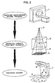
- Fig. 1 is a flowchart showing a radiograph generation method, which is an embodiment of an image processing method to which the present invention is applied. The flowchart will be described with reference to the process of a radiotherapy treatment shown in Fig. 2.
- the image of an area including an affected part is made using a tomographic image measurement apparatus 1 such as an X-ray CT unit shown in Fig. 2 before a patient is subjected to a treatment, and thus three-dimensional image data is prepared (Step 101).
- a tomographic image measurement apparatus 1 such as an X-ray CT unit shown in Fig. 2 before a patient is subjected to a treatment, and thus three-dimensional image data is prepared (Step 101).
- irradiation conditions necessary for treating the patient with a radiotherapy treatment unit 7 are set (step 102).
- the irradiation conditions include the position 3 of a radiation source, the isocenter position 4 onto which radiation is focused, the degree of expansion of a radiation beam 5 and so forth.
- the position of the radiation source is rotatable about the specified isocenter by rotating and moving a gantry 8 and a table 9 of the radiotherapy treatment unit 7.
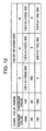
- a color information conversion table corresponding to voxel data (hereinafter referred to as "voxel values”) such as CT values is set (Step 103).
- the table contains color information corresponding to a range of voxel values in terms of RGB ratio, as shown, e.g., in Fig. 12, where V is the voxel value.
- the table shown in Fig. 12 can allocate values linearly within the range of voxel values.
- the voxel values ranging from -1000 to -100 are converted to the color information of gray having gradations ranging from 0 to 128, the voxel values mainly indicating vascular areas and ranging from -99 to 99 are converted to the color information of red having a gradation of 200, and the voxel values mainly indicating bones and ranging from 100 to 1000 are converted to the color information of yellow having 0 to 255 gradations.
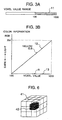
- FIG. 3A An embodiment of a method by which a user specifies the color information table is shown in Figs. 3A and 3B.
- the user specifies a range 11 for which color information is obtained.
- the range 11 can be selected by, e.g., dragging both ends of a target range 11 using a mouse.
- the user prepares the color information table corresponding to the selected voxel value range.
- the user specification is such that colors G and B change as shown by a line 12 and that color R remains at 0 as shown by a line 13.
- These lines are specified by, e.g., dragging the ends of each line using the mouse.
- the color information table such as shown in Fig. 12 can be prepared automatically.
- a DRR which is a radiograph, is produced by sequentially calculating all the pixels on the DRR.
- Step 106 assuming a ray connecting a pixel on the DRR and the radiation source, voxel values on such ray are interpolated (Step 106 (since Steps 104 and 105 result in "NO" in the first operation, so that the process proceeds to step 106)).
- the interpolated voxel values are converted to color information by means of the color information table set in Step 103 (Step 107).
- pieces of the converted color information are added up to a memory for storing the pixel values of the DRR (Step 108).
- the pixel value storing memory is initially cleared, and the pieces of color information corresponding to the voxel values on the ray are sequentially added up. The addition is made on a color component (R, G, B) basis.
- This calculation is made for all the voxel values in the three-dimensional data present on the ray (Step 105). Upon completion of the calculation for all the pixels on the DRR (Step 104), the calculated DRR is displayed (Step 109).
- the DRR may, thereafter, be printed or stored in a hard disk, etc.
- different colors can be used to display different areas that are specified by respective voxel value ranges, and this allows the user to highlight areas of interest in preparing a treatment design.
- a sliced image 21 is displayed.
- the position of the displayed cross-sectional image is indicated in the form of a line 23 on a scanogram 22 so that the user can locate the position.
- the position of the sliced image 21 can be moved by dragging the line 23 with the mouse or the slicing position can be moved with a slider 24.
- a single point in an area to be highlighted is specified on the sliced image 21 using a pointer 25.
- the voxel value V of the specified point is retrieved, and the retrieved value V is set as the central value of a voxel value range 26, so that the range 26 covering an interval of ⁇ ⁇ from the central value V can thereafter be set for preparing a color information table. While a predetermined initial value is used as ⁇ , the interval ⁇ can be altered by dragging either the upper end or lower end of the color information setting range with the mouse.
- the voxel value range is specified in this way, the color information table is prepared based on the method described with reference to Figs. 3A and 3B. This method allows the user to visually specify the voxel values of the area to be highlighted.
- the voxel value range specifying operation becomes easier.
- such area may be specified by determining the voxel value range for color information specification based on the maximum and minimum values of the voxel values contained in a rectangular area.
- a display method by which a structure such as a bone can be easily identified on a DRR by smoothly enhancing the contour of the structure such as a bone will be described with reference to Figs. 5A to 5D.
- an edge process may be performed so that a voxel value at a position where there is an abrupt voxel value change is converted into a higher value than voxel values adjacent to such voxel value.
- An embodiment of the present invention, in which a DRR is prepared using edge-processed data will be described below. Since techniques based on differential analyses produce data plenty of noise with highfrequency components emphasized, a technique based on a standard deviation is used in this embodiment to express desired voxel values.
- a standard deviation ⁇ can be given by equation 1, assuming that the number of voxels within a block is n and that the density of a voxel i is v i .
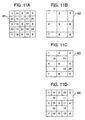
- Figs. 5A to 5D show the results of an edge process that is performed with a block size of 3x3 using two-dimensional data.
- the 3x3 block is the minimum unit for performing the edge process, and the two-dimensional data is used for a concise description.
- Fig. 5C shows the results 32 of an edge process performed by calculating a 3x3-block-based standard deviation for an area surrounded by the thick line in two-dimensional data 31 shown in Fig. 5A.
- the graphs on the right show changes in the data.
- the graph 33 shows a change in the original data surrounded by the thick line and the graph 34 shows a change in the edge-processed data.
- the numerals given on the horizontal axes of the graphs 5B and 5D correspond to the numerals superscribed on the original data surrounded by the thick line.
- the edge in the original data surrounded by the thick line is assumed to be located between the second and third pixels from the left. It is verified that the contour is enhanced in the graph 34 that is edge-processed by means of a standard deviation with high values given between the second and third pixels as an edge. Further, there is another edge between the fifth and sixth pixels from the left in the original data. This edge, having a smaller density difference than the first edge, is expressed by smaller values in the edge-processed data 32. Another edge between the sixth and seventh pixels from the left in the original data, having a further smaller density difference, is expressed by further smaller values in the edge-processed graph.
- the edge-processed data is obtained by converting the original data as if the edge were present between voxels of the original data, i.e., between the second and third pixels of the original data.
- the contour is extended by one pixel.
- the conversion is performed so that the edge-processed voxels 2 and 3 represent an edge.
- this technique provides smoothing effects, which reduces noise and hence allows the contour of the structure such as a bone to be enhanced satisfactorily.
- edge process described in terms of two-dimensional data shown in Figs. 5A to 5D can be applied directly to the horizontal and vertical directions of three-dimensional data.
- Three-dimensional data is subjected to an edge process in the following way.
- a standard deviation is calculated using a 3x3x3 block 41 around a voxel 42 that is subjected to an edge process, as shown in Fig. 6, satisfactory results can be obtained.
- the edge process cannot be performed on all the voxels on the outermost sides of the three-dimensional data. However, it is negligible since it is a small area in comparison with all data quantity.
- the edge-processed three-dimensional data is the edge-enhanced data in which portions of the original three-dimensional image with their densities drastically changed, i.e., edge portions are enhanced.
- Fig. 7 is a flowchart, which is an embodiment of the present invention.
- the flowchart presents a process using an edge process and a color information conversion table.
- the process steps identical to those shown in Fig. 1 are denoted by the same step numbers.
- a standard deviation ⁇ of the three-dimensional image data measured by a tomographic image measurement apparatus is calculated by the equation 1, and a second version of three-dimensional data is obtained by expressing the original three-dimensional image data using ⁇ in Step 201.
- the image process is performed using the second version of three-dimensional data.
- Step 201 may be performed immediately after Step 102 or immediately after Step 103.
- Fig. 8 shows another embodiment of a flowchart showing an edge process.
- the flowchart of Fig. 8 is distinguished from that of Fig. 7 in that the color information conversion table is not used. Therefore, Steps 103 and 107 in the flowchart of Fig. 7 are eliminated, and Step 202 replaces Step 108.
- Step 202 voxel values are added up to a memory for storing pixels on a projected image. Other steps are identical to those of Figs. 1 and 7.
- Fig. 9 is a cross section taken from a diagram showing the treatment planning of Fig. 2.
- the DRR is set so as to coincide with a plane 6 that includes the isocenter 4.
- the three-dimensional data 2 is projected onto the DRR plane 6 through the radiation beam 5 from the radiation source 3.
- the three-dimensional data is added up and projected in both forward and backward directions indicated by arrows.
- the DRR calculation method includes an image-order approach in which a DRR is calculated in the order of pixels or an object-order approach in which a DRR is calculated in the order of three dimensional data.
- the projected position of the DRR is on a plane including the isocenter. Since voxels which are remoter from the radiation source than the projected area and considered invalid in ordinary projections are projected, all the three-dimensional data can be visualized as the DRR. If the user wishes to generate a DRR in which only an area of interest is focused, all the data may not necessarily be visualized by limiting the area for calculation.
- the isocenter is usually set to the center of an affected part to be treated, and the range of irradiation is often set on a plane including the isocenter.
- the irradiation range is displayed on a DRR by setting the pixel size of the DRR to coincide with the minimum value of the voxel size.
- the image of the affected part on the DRR becomes as big as the actual affected part.
- the DRR on the plane including the isocenter that is the center of an area of interest allows the user to make simulations easily.
- Fig. 10 shows how a DRR is generated in the form of a cross section.
- the DRR can be generated by using a color information conversion table and an edge process.
- the resolution (pixel size) 52 and number of pixels of a DRR are specified.
- a value equal to the resolution (voxel size) of the three-dimensional data is set as an initial value (the finest resolution value is set in case of that the voxel size has different lengths), and such number of pixels as to allow all the three-dimensional data as to be projected (such number can be obtained from the radiation source, isocenter position, number of three-dimensional data voxels, resolution, and the like) is specified.
- a sampling interval 53 on the ray connecting the radiation source 3 to the pixel 51 is specified.
- the value equal to the resolution of the DRR is specified as an initial value. Using the aforementioned initial values, the DRR corresponding to the quality of the three-dimensional data can be calculated.
- the number of pixels of the DRR can be reduced, or the sampling interval between voxels on the ray connecting the radiation source to the pixel is increased. As a result, the DRR can be calculated faster. If the number of pixels of the DRR is reduced without changing the resolution, the projection range is reduced, but the image quality remains unchanged. On the other hand, if not only the number of pixels is reduced but also the resolution is reduced accordingly, the image quality is impaired, but the projection range remains unchanged. The above similarly applies to the sampling interval between voxels on the ray. Further, if the user wishes to improve the image quality, the resolution of the DRR may be increased, or the sampling interval between voxels on the ray may be reduced.
- the aforementioned embodiment allows calculation speed and image quality to be controlled in accordance with the usage of an image and the capacity of a computer.
- Figs. 11A to 11D show a method in which calculations for generating a 5x5-pixel-based DRR are made on four steps and the calculated image is displayed every time the calculation is made.
- the DRR can be generated by using a color information conversion table and an edge process.
- pixels 1 to 9 are calculated every other pixel in both horizontal and vertical directions.
- a first-step DRR 62 is generated from the initially calculated nine pixels, and the generated DRR 62 is displayed.
- the first DRR is displayed with the skipped pixel values (e.g., 14, 20, 10) represented as the calculated pixel values (e.g., 1) (Fig. 11B).
- pixels 10 to 13, each being located at a position one pixel moved in both horizontal and vertical directions from the initially calculated pixel are calculated.
- a second-step DRR 63 is generated using the calculated thirteen pixels and displayed. In this case, the pixels on the left of the pixels 10 to 13 are displayed as the same values (Fig. 11C).
- pixels 14 to 19 each being located at a position one pixel moved in the horizontal direction from the initially calculated pixel, are calculated to generate and display a third-step DRR 64 using the nineteen pixels (Fig. 11D).
- the remaining pixels 20 to 25 are calculated to generate and display the final DRR 61 (Fig. 11A).
- the user can grasp the outline of the DRR with the images 62, 63 and 64 on the intermediate steps sequentially displayed before all the pixels of the final DRR 61 are completely calculated.
- interactivity can be improved.
- the total time required for completing all the calculations, although a small time to generate the intermediate images is included, is substantially the same as that required in the method in which a DRR is displayed after all the pixels are directly calculated.
- Fig. 13 is a block diagram showing an exemplary image processing apparatus that embodies the image processing method of the present invention.
- the image processing apparatus comprises an operation section 71, a memory 72, an input unit 73, a display unit 74, a radiotherapy treatment unit 75 and a tomographic image measurement apparatus 76.
- the operation section 71 includes a CPU, a ROM and a RAM and executes various processes such as a process for calculating a DRR using a color information conversion table and three-dimensional data subjected to a standard-deviation process.
- the memory 72 stores three-dimensional image data, edge-processed data, a color information conversion table such as shown in Fig. 12, DRR data and the like.
- the input unit 73 is a device such as a keyboard and a mouse.
- the display unit 74 displays an image that is digitally reconstructed by calculation.
- the radiotherapy treatment unit 75 is connected to the image processing apparatus through an interface section.
- the tomographic image measurement apparatus 76 such as CT apparatus or NMR apparatus is connected to the image processing apparatus through an interface section.
- the present invention is not limited to the aforementioned embodiments.
- the present invention also includes various modifications to be made within the scope of the claims annexed to and forming a part of this specification.
Landscapes
- Physics & Mathematics (AREA)
- General Physics & Mathematics (AREA)
- Engineering & Computer Science (AREA)
- Theoretical Computer Science (AREA)
- Image Processing (AREA)
- Apparatus For Radiation Diagnosis (AREA)
- Image Generation (AREA)
- Radiation-Therapy Devices (AREA)
- Image Analysis (AREA)
Claims (16)
- Bildverarbeitungsvorrichtung, mit:gekennzeichnet durcheinem Speicher zum Speichern dreidimensionaler Daten (72);einer Tabelle (Fig. 13, 72) zum Zuordnen von Farbinformationen, so dass sie Volumenelement- bzw. Voxel-Werten entsprechen;einer Operationssektion (71) zum Erzeugen eines DRR (digital rekonstruiertes Röntgenbild) durch Interpolieren von Voxel-Werten auf einem von einer Strahlungsquelle eingestrahlten Strahl und Aufaddieren von Farbinformationen entlang dem Strahl; undeiner Anzeigeeinheit (74) zum Anzeigen des erzeugten DRR-Bildes;
die Operationssektion (71) zum Aufaddieren der Farbinformationen entlang dem Strahl, wobei die Farbinformationen erhalten werden, indem die interpolierten Voxel-Werte basierend auf der Tabelle umgewandelt werden. - Bildverarbeitungsvorrichtung nach Anspruch 1, worin die Operationssektion (71) zum Erzeugen des DRR Einrichtungen zum Festlegen einer Ebene (6) des DRR enthält, so dass sie mit einer ein Isozentrum (4) enthaltenen Ebene übereinstimmt.
- Bildverarbeitungsvorrichtung nach Anspruch 2, femer mit einer Einrichtung zum Ausdrücken der dreidimensionalen Daten unter Verwendung einer Standardabweichung.
- Bildverarbeitungsvorrichtung nach Anspruch 3, worin die Operationssektion (71) verwendet wird, um die Standardabweichung der dreidimensionalen Daten zu berechnen und dann eine zweite Version dreidimensionaler Daten zu berechnen, in der die dreidimensionalen Daten unter Verwendung der Standardabweichung ausgedrückt werden.
- Bildverarbeitungsvorrichtung nach Anspruch 2, worin die Operationssektion (71) zum Erzeugen des DRR eine Einrichtung enthält, um Voxel-Werte in Richtung auf die Strahlungsquelle zu projizieren, wobei die Voxel der Strahlungsquelle bezüglich der Ebene (6) des DRR gegenüberliegen.
- Bildverarbeitungsvorrichtung nach Anspruch 1, worin die Operationssektion (71) zum Erzeugen des DRR eine Einrichtung zum Festlegen einer Auflösung (52) des DRR auf einen gewünschten Wert enthält.
- Bildverarbeitungsvorrichtung nach Anspruch 1, worin die Operationssektion (71) zum Erzeugen des DRR eine Einrichtung zum Festlegen eines Abtastintervalls (53) zwischen Voxet auf einem die Strahlungsquelle mit einem Pixel des DRR verbindenden Strahl auf einen gewünschten Wert enthält.
- Bildverarbeitungsvorrichtung nach Anspruch 1, worin die Operationssektion (71) zum Erzeugen des DRR enthält
eine Einrichtung zum partiellen Auswählen von Pixel des DRR und Berechnen von Werten der ausgewählten Pixel und
eine Einrichtung zum Rekonstruieren der DRRs (62, 63, 64) unter Verwendung der teilweise berechneten Pixelwerte, worin
die Anzeigeeinheit (74) eine Einrichtung zum sequentiellen Anzeigen der unter Verwendung der teilweise berechneten Pixelwerte rekonstruierten DRRs enthält. - Bildverarbeitungsverfahren, aufweisend:einen Schritt (101) zum Erzeugen dreidimensionaler Daten;einen Schritt (102) zum Festlegen von Strahlungsbedingungen;einen Schritt (103) zum Festlegen einer Tabelle zum Zuordnen von Farbinformationen, so dass sie Voxel-Werten entsprechen;einen Schritt (106) zum Interpolieren von Voxel-Werten auf einem von einer Strahlungsquelle eingestrahlten Strahl;einen Schritt (107, 108, 104, 105) zum Erzeugen eines DRR (digital konstruierten Röntgenbild), indem Farbinformationen entlang dem Strahl aufaddiert werden, wobei die Farbinformationen erhalten werden, indem die interpolierten Voxel-Werte basierend auf der Tabelle umgewandelt werden; undeinen Schritt (109) zum Anzeigen des erzeugten DRR.
- Bildverarbeitungsverfahren nach Anspruch 9, worin der Schritt zum Erzeugen des DRR einen Schritt zum Festlegen einer Ebene (6) des DRR enthält, so dass sie mit einer ein Isozentrum (4) enthaltenden Ebene übereinstimmt.
- Bildverarbeitungsverfahren nach Anspruch 9, ferner mit einem Schritt (201) zum Ausdrücken der dreidimensionalen Daten durch Berechnen einer Standardabweichung.
- Bildverarbeitungsverfahren nach Anspruch 11, worin der Schritt zum Ausdrücken der dreidimensionalen Daten aufweist
einen Schritt (201) zum Berechnen einer zweiten Version dreidimensionaler Daten durch Berechnen der Standardabweichung der dreidimensionalen Daten. - Bildverarbeitungsverfahren nach Anspruch 9, worin der Schritt zum Erzeugen des DRR einen Schritt zum Projizieren von Voxel-Werten in Richtung auf die Strahlungsquelle enthält, wobei die Voxel der Strahlungsquelle bezüglich der Ebene (6) des DRR gegenüberliegen.
- Bildverarbeitungsverfahren nach Anspruch 9, worin der Schritt zum Erzeugen des DRR einen Schritt zum Festlegen einer Auflösung (52) des DRR auf einen gewünschten Wert enthält.
- Bildverarbeitungsverfahren nach Anspruch 9, worin der Schritt zum Erzeugen des DRR einen Schritt einschließt, der ein Abtastintervall (53) zwischen Voxel auf einem die Strahlungsquelle mit einem Pixel des DRR verbindenden Strahl auf einen gewünschten Wert festlegt.
- Bildverarbeitungsverfahren nach Anspruch 9, worin der Schritt zum Erzeugen des DRR einschließt
einen Schritt zum teilweisen Auswählen von Pixel des DRR und Berechnen von Werten der ausgewählten Pixel und
einen Schritt zum Rekonstruieren der DRRs (62, 63, 64) unter Verwendung der teilweise berechneten Pixelwerte, worin
der Schritt zum Anzeigen einen Schritt zum sequentiellen Anzeigen der unter Verwendung der teilweise berechneten Pixeiwerte rekonstruierten DRRs einschließt.
Applications Claiming Priority (3)
| Application Number | Priority Date | Filing Date | Title |
|---|---|---|---|
| JP156371/97 | 1997-06-13 | ||
| JP15637197A JP3896188B2 (ja) | 1997-06-13 | 1997-06-13 | 放射線治療計画のための画像処理装置 |
| JP15637197 | 1997-06-13 |
Publications (3)
| Publication Number | Publication Date |
|---|---|
| EP0884697A2 EP0884697A2 (de) | 1998-12-16 |
| EP0884697A3 EP0884697A3 (de) | 2000-01-05 |
| EP0884697B1 true EP0884697B1 (de) | 2003-08-27 |
Family
ID=15626299
Family Applications (1)
| Application Number | Title | Priority Date | Filing Date |
|---|---|---|---|
| EP98110408A Expired - Lifetime EP0884697B1 (de) | 1997-06-13 | 1998-06-08 | Bildverarbeitungsverfahren und -vorrichtung für die Strahlentherapie unter Verwendung von Computer-Tomographie |
Country Status (4)
| Country | Link |
|---|---|
| US (1) | US6549645B1 (de) |
| EP (1) | EP0884697B1 (de) |
| JP (1) | JP3896188B2 (de) |
| DE (1) | DE69817458T2 (de) |
Families Citing this family (42)
| Publication number | Priority date | Publication date | Assignee | Title |
|---|---|---|---|---|
| JP4149126B2 (ja) * | 2000-12-05 | 2008-09-10 | ジーイー・メディカル・システムズ・グローバル・テクノロジー・カンパニー・エルエルシー | 画像処理方法、画像処理装置および画像撮影装置 |
| US7203266B2 (en) | 2002-03-26 | 2007-04-10 | Hitachi Medical Corporation | Image display method and method for performing radiography of image |
| JP4253497B2 (ja) * | 2002-12-03 | 2009-04-15 | 株式会社東芝 | コンピュータ支援診断装置 |
| JP2005202791A (ja) * | 2004-01-16 | 2005-07-28 | Med Solution Kk | 画像を生成する方法、装置およびプログラム |
| US7653226B2 (en) * | 2004-04-21 | 2010-01-26 | Siemens Medical Solutions Usa, Inc. | Flexible generation of digitally reconstructed radiographs |
| US7231076B2 (en) * | 2004-06-30 | 2007-06-12 | Accuray, Inc. | ROI selection in image registration |
| US7366278B2 (en) * | 2004-06-30 | 2008-04-29 | Accuray, Inc. | DRR generation using a non-linear attenuation model |
| US7522779B2 (en) * | 2004-06-30 | 2009-04-21 | Accuray, Inc. | Image enhancement method and system for fiducial-less tracking of treatment targets |
| US7327865B2 (en) * | 2004-06-30 | 2008-02-05 | Accuray, Inc. | Fiducial-less tracking with non-rigid image registration |
| US7426318B2 (en) * | 2004-06-30 | 2008-09-16 | Accuray, Inc. | Motion field generation for non-rigid image registration |
| US7330578B2 (en) * | 2005-06-23 | 2008-02-12 | Accuray Inc. | DRR generation and enhancement using a dedicated graphics device |
| US7620227B2 (en) * | 2005-12-29 | 2009-11-17 | General Electric Co. | Computer-aided detection system utilizing temporal analysis as a precursor to spatial analysis |
| US20080037843A1 (en) * | 2006-08-11 | 2008-02-14 | Accuray Incorporated | Image segmentation for DRR generation and image registration |
| JP2009082407A (ja) * | 2007-09-28 | 2009-04-23 | Toshiba Corp | 画像処理装置及び医用画像処理装置 |
| JP5729907B2 (ja) * | 2009-02-23 | 2015-06-03 | 株式会社東芝 | X線診断装置 |
| US8693634B2 (en) | 2010-03-19 | 2014-04-08 | Hologic Inc | System and method for generating enhanced density distribution in a three dimensional model of a structure for use in skeletal assessment using a limited number of two-dimensional views |
| US9779504B1 (en) | 2011-12-14 | 2017-10-03 | Atti International Services Company, Inc. | Method and system for identifying anomalies in medical images especially those including one of a pair of symmetric body parts |
| JP5173050B2 (ja) * | 2012-06-04 | 2013-03-27 | 株式会社東芝 | 医用画像処理装置 |
| JP6301793B2 (ja) * | 2014-09-18 | 2018-03-28 | 株式会社島津製作所 | Drr画像作成方法およびdrr画像作成装置 |
| GB2536650A (en) | 2015-03-24 | 2016-09-28 | Augmedics Ltd | Method and system for combining video-based and optic-based augmented reality in a near eye display |
| DE102015207107A1 (de) * | 2015-04-20 | 2016-10-20 | Siemens Healthcare Gmbh | Verfahren zur Erzeugung einer virtuellen Röntgenprojektion anhand eines mittels Röntgenbildaufnahmevorrichtung erhaltenen Bilddatensatzes, Computerprogramm, Datenträger sowie Röntgenbildaufnahmevorrichtung |
| JP6668902B2 (ja) * | 2016-04-12 | 2020-03-18 | 株式会社島津製作所 | 位置決め装置および位置決め装置の作動方法 |
| US10102640B2 (en) | 2016-11-29 | 2018-10-16 | Optinav Sp. Z O.O. | Registering three-dimensional image data of an imaged object with a set of two-dimensional projection images of the object |
| WO2018161257A1 (zh) | 2017-03-07 | 2018-09-13 | 上海联影医疗科技有限公司 | 生成彩色医学影像的方法及系统 |
| US12521201B2 (en) | 2017-12-07 | 2026-01-13 | Augmedics Ltd. | Spinous process clamp |
| US12458411B2 (en) | 2017-12-07 | 2025-11-04 | Augmedics Ltd. | Spinous process clamp |
| EP3787543A4 (de) | 2018-05-02 | 2022-01-19 | Augmedics Ltd. | Registrierung einer bezugsmarke für ein system der erweiterten realität |
| US11766296B2 (en) | 2018-11-26 | 2023-09-26 | Augmedics Ltd. | Tracking system for image-guided surgery |
| US11980506B2 (en) | 2019-07-29 | 2024-05-14 | Augmedics Ltd. | Fiducial marker |
| US12178666B2 (en) | 2019-07-29 | 2024-12-31 | Augmedics Ltd. | Fiducial marker |
| CN110458950A (zh) * | 2019-08-14 | 2019-11-15 | 首都医科大学附属北京天坛医院 | 一种三维模型重建方法、移动终端、存储介质及电子设备 |
| US11382712B2 (en) | 2019-12-22 | 2022-07-12 | Augmedics Ltd. | Mirroring in image guided surgery |
| US11389252B2 (en) | 2020-06-15 | 2022-07-19 | Augmedics Ltd. | Rotating marker for image guided surgery |
| US12239385B2 (en) | 2020-09-09 | 2025-03-04 | Augmedics Ltd. | Universal tool adapter |
| US12502163B2 (en) | 2020-09-09 | 2025-12-23 | Augmedics Ltd. | Universal tool adapter for image-guided surgery |
| JP7691062B2 (ja) * | 2021-02-26 | 2025-06-11 | 東芝エネルギーシステムズ株式会社 | 放射線治療装置、医用画像処理装置、放射線治療方法、およびプログラム |
| US11896445B2 (en) | 2021-07-07 | 2024-02-13 | Augmedics Ltd. | Iliac pin and adapter |
| US12150821B2 (en) | 2021-07-29 | 2024-11-26 | Augmedics Ltd. | Rotating marker and adapter for image-guided surgery |
| US12475662B2 (en) | 2021-08-18 | 2025-11-18 | Augmedics Ltd. | Stereoscopic display and digital loupe for augmented-reality near-eye display |
| JP7345768B1 (ja) * | 2022-03-30 | 2023-09-19 | 国立大学法人大阪大学 | 予測支援システム、予測支援方法及び予測支援プログラム |
| WO2023203521A1 (en) | 2022-04-21 | 2023-10-26 | Augmedics Ltd. | Systems and methods for medical image visualization |
| JP2025531829A (ja) | 2022-09-13 | 2025-09-25 | オーグメディックス リミテッド | 画像誘導医療介入のための拡張現実アイウェア |
Family Cites Families (21)
| Publication number | Priority date | Publication date | Assignee | Title |
|---|---|---|---|---|
| US4585992A (en) * | 1984-02-03 | 1986-04-29 | Philips Medical Systems, Inc. | NMR imaging methods |
| US4737921A (en) * | 1985-06-03 | 1988-04-12 | Dynamic Digital Displays, Inc. | Three dimensional medical image display system |
| FR2597227B1 (fr) * | 1986-04-14 | 1992-09-11 | Pixar | Procede pour produire un affichage bidimensionnel representant un ensemble de donnees tridimensionnelles |
| US4984157A (en) * | 1988-09-21 | 1991-01-08 | General Electric Company | System and method for displaying oblique planar cross sections of a solid body using tri-linear interpolation to determine pixel position dataes |
| US5151856A (en) * | 1989-08-30 | 1992-09-29 | Technion R & D Found. Ltd. | Method of displaying coronary function |
| US5947981A (en) * | 1995-01-31 | 1999-09-07 | Cosman; Eric R. | Head and neck localizer |
| US5233299A (en) * | 1991-03-25 | 1993-08-03 | General Electric Company | Projection methods for producing two-dimensional images from three-dimensional data |
| US5283837A (en) * | 1991-08-27 | 1994-02-01 | Picker International, Inc. | Accurate estimation of surface normals in 3-D data sets |
| GB9209500D0 (en) * | 1992-05-01 | 1992-06-17 | Link Analytical Ltd | X-ray analysis apparatus |
| US5280428A (en) * | 1992-07-14 | 1994-01-18 | General Electric Company | Method and apparatus for projecting diagnostic images from volumed diagnostic data accessed in data tubes |
| US5568384A (en) * | 1992-10-13 | 1996-10-22 | Mayo Foundation For Medical Education And Research | Biomedical imaging and analysis |
| US5368033A (en) * | 1993-04-20 | 1994-11-29 | North American Philips Corporation | Magnetic resonance angiography method and apparatus employing an integration projection |
| CN1164904A (zh) * | 1994-09-06 | 1997-11-12 | 纽约州州立大学研究基金会 | 实时立体显象设备与方法 |
| US5570460A (en) * | 1994-10-21 | 1996-10-29 | International Business Machines Corporation | System and method for volume rendering of finite element models |
| US5471990A (en) * | 1994-11-23 | 1995-12-05 | Advanced Technology Laboratories, Inc. | Ultrasonic doppler power measurement and display system |
| JP3748113B2 (ja) | 1994-12-12 | 2006-02-22 | 株式会社東芝 | Ctシステム |
| US5594807A (en) * | 1994-12-22 | 1997-01-14 | Siemens Medical Systems, Inc. | System and method for adaptive filtering of images based on similarity between histograms |
| US5621779A (en) * | 1995-07-20 | 1997-04-15 | Siemens Medical Systems, Inc. | Apparatus and method for delivering radiation to an object and for displaying delivered radiation |
| JPH09154961A (ja) * | 1995-12-07 | 1997-06-17 | Toshiba Medical Eng Co Ltd | 放射線治療計画法 |
| WO1997041532A1 (en) * | 1996-04-29 | 1997-11-06 | The Government Of The United States Of America, Represented By The Secretary, Department Of Health And Human Services | Iterative image registration process using closest corresponding voxels |
| US6008813A (en) * | 1997-08-01 | 1999-12-28 | Mitsubishi Electric Information Technology Center America, Inc. (Ita) | Real-time PC based volume rendering system |
-
1997
- 1997-06-13 JP JP15637197A patent/JP3896188B2/ja not_active Expired - Fee Related
-
1998
- 1998-06-08 EP EP98110408A patent/EP0884697B1/de not_active Expired - Lifetime
- 1998-06-08 DE DE69817458T patent/DE69817458T2/de not_active Expired - Fee Related
- 1998-06-10 US US09/094,489 patent/US6549645B1/en not_active Expired - Fee Related
Also Published As
| Publication number | Publication date |
|---|---|
| DE69817458T2 (de) | 2004-03-11 |
| DE69817458D1 (de) | 2003-10-02 |
| JP3896188B2 (ja) | 2007-03-22 |
| JPH11409A (ja) | 1999-01-06 |
| US6549645B1 (en) | 2003-04-15 |
| EP0884697A3 (de) | 2000-01-05 |
| EP0884697A2 (de) | 1998-12-16 |
Similar Documents
| Publication | Publication Date | Title |
|---|---|---|
| EP0884697B1 (de) | Bildverarbeitungsverfahren und -vorrichtung für die Strahlentherapie unter Verwendung von Computer-Tomographie | |
| CN100573588C (zh) | 使用截短的投影和在先采集的3d ct图像的锥形束ct设备 | |
| US7873403B2 (en) | Method and device for determining a three-dimensional form of a body from two-dimensional projection images | |
| Zellerhoff et al. | Low contrast 3D reconstruction from C-arm data | |
| McShan et al. | Full integration of the beam's eye view concept into computerized treatment planning | |
| US7433507B2 (en) | Imaging chain for digital tomosynthesis on a flat panel detector | |
| US7920669B2 (en) | Methods, apparatuses and computer readable mediums for generating images based on multi-energy computed tomography data | |
| US4989142A (en) | Three-dimensional images obtained from tomographic slices with gantry tilt | |
| JP2007203046A (ja) | 対象の画像スライスを作成するための方法及びシステム | |
| JP2003198941A (ja) | デジタルポータル画像のコントラストを強調する方法 | |
| CN1620990A (zh) | 在ct血管造影术中分割结构的方法及设备 | |
| US7639867B2 (en) | Medical image generating apparatus and method, and program | |
| JPH10262960A (ja) | 部分体積アーチファクト低減方法およびシステム | |
| KR20080034447A (ko) | 2차원 x-선 영상과 3차원 초음파 영상의 선택적인 혼합을위한 시스템 및 방법 | |
| CN109472835A (zh) | 处理医学图像数据的方法和医学图像数据的图像处理系统 | |
| Bär et al. | Improving radiotherapy planning in patients with metallic implants using the iterative metal artifact reduction (iMAR) algorithm | |
| JP2004174241A (ja) | 画像形成方法 | |
| US7738701B2 (en) | Medical image processing apparatus, ROI extracting method and program | |
| EP1415276B1 (de) | Vorrichtung zur geräuschreduzierung für eine räumliche abbildung | |
| US20060071932A1 (en) | Method and apparatus for visualizing a sequece of volume images | |
| JP7003635B2 (ja) | コンピュータプログラム、画像処理装置及び画像処理方法 | |
| EP3830788B1 (de) | Verfahren zur bereitstellung einer automatischen adaptiven energieeinstellung für virtuelle monochromatische ct-bildaufnahme | |
| US7116808B2 (en) | Method for producing an image sequence from volume datasets | |
| JPH0728976A (ja) | 画像表示装置 | |
| CN113853636A (zh) | 用于提供近似图像的方法、计算机程序产品和计算机系统 |
Legal Events
| Date | Code | Title | Description |
|---|---|---|---|
| PUAI | Public reference made under article 153(3) epc to a published international application that has entered the european phase |
Free format text: ORIGINAL CODE: 0009012 |
|
| 17P | Request for examination filed |
Effective date: 19980608 |
|
| AK | Designated contracting states |
Kind code of ref document: A2 Designated state(s): DE FR GB NL |
|
| AX | Request for extension of the european patent |
Free format text: AL;LT;LV;MK;RO;SI |
|
| PUAL | Search report despatched |
Free format text: ORIGINAL CODE: 0009013 |
|
| AK | Designated contracting states |
Kind code of ref document: A3 Designated state(s): AT BE CH CY DE DK ES FI FR GB GR IE IT LI LU MC NL PT SE |
|
| AX | Request for extension of the european patent |
Free format text: AL;LT;LV;MK;RO;SI |
|
| AKX | Designation fees paid |
Free format text: DE FR GB NL |
|
| 17Q | First examination report despatched |
Effective date: 20020531 |
|
| GRAH | Despatch of communication of intention to grant a patent |
Free format text: ORIGINAL CODE: EPIDOS IGRA |
|
| GRAH | Despatch of communication of intention to grant a patent |
Free format text: ORIGINAL CODE: EPIDOS IGRA |
|
| GRAA | (expected) grant |
Free format text: ORIGINAL CODE: 0009210 |
|
| AK | Designated contracting states |
Designated state(s): DE FR GB NL |
|
| REG | Reference to a national code |
Ref country code: GB Ref legal event code: FG4D |
|
| REF | Corresponds to: |
Ref document number: 69817458 Country of ref document: DE Date of ref document: 20031002 Kind code of ref document: P |
|
| ET | Fr: translation filed | ||
| PLBE | No opposition filed within time limit |
Free format text: ORIGINAL CODE: 0009261 |
|
| STAA | Information on the status of an ep patent application or granted ep patent |
Free format text: STATUS: NO OPPOSITION FILED WITHIN TIME LIMIT |
|
| 26N | No opposition filed |
Effective date: 20040528 |
|
| PGFP | Annual fee paid to national office [announced via postgrant information from national office to epo] |
Ref country code: NL Payment date: 20080626 Year of fee payment: 11 Ref country code: DE Payment date: 20080626 Year of fee payment: 11 |
|
| PGFP | Annual fee paid to national office [announced via postgrant information from national office to epo] |
Ref country code: FR Payment date: 20080423 Year of fee payment: 11 |
|
| PGFP | Annual fee paid to national office [announced via postgrant information from national office to epo] |
Ref country code: GB Payment date: 20080418 Year of fee payment: 11 |
|
| GBPC | Gb: european patent ceased through non-payment of renewal fee |
Effective date: 20090608 |
|
| NLV4 | Nl: lapsed or anulled due to non-payment of the annual fee |
Effective date: 20100101 |
|
| REG | Reference to a national code |
Ref country code: FR Ref legal event code: ST Effective date: 20100226 |
|
| PG25 | Lapsed in a contracting state [announced via postgrant information from national office to epo] |
Ref country code: FR Free format text: LAPSE BECAUSE OF NON-PAYMENT OF DUE FEES Effective date: 20090630 |
|
| PG25 | Lapsed in a contracting state [announced via postgrant information from national office to epo] |
Ref country code: GB Free format text: LAPSE BECAUSE OF NON-PAYMENT OF DUE FEES Effective date: 20090608 |
|
| PG25 | Lapsed in a contracting state [announced via postgrant information from national office to epo] |
Ref country code: DE Free format text: LAPSE BECAUSE OF NON-PAYMENT OF DUE FEES Effective date: 20100101 |
|
| PG25 | Lapsed in a contracting state [announced via postgrant information from national office to epo] |
Ref country code: NL Free format text: LAPSE BECAUSE OF NON-PAYMENT OF DUE FEES Effective date: 20100101 |