EP0884713A2 - Befestigungsvorrichtung für Anzeigetafel - Google Patents
Befestigungsvorrichtung für Anzeigetafel Download PDFInfo
- Publication number
- EP0884713A2 EP0884713A2 EP98110836A EP98110836A EP0884713A2 EP 0884713 A2 EP0884713 A2 EP 0884713A2 EP 98110836 A EP98110836 A EP 98110836A EP 98110836 A EP98110836 A EP 98110836A EP 0884713 A2 EP0884713 A2 EP 0884713A2
- Authority
- EP
- European Patent Office
- Prior art keywords
- frames
- frame
- attachment
- display panel
- fixing
- Prior art date
- Legal status (The legal status is an assumption and is not a legal conclusion. Google has not performed a legal analysis and makes no representation as to the accuracy of the status listed.)
- Withdrawn
Links
- 230000002093 peripheral effect Effects 0.000 claims abstract description 22
- 238000007373 indentation Methods 0.000 claims description 3
- 229910052751 metal Inorganic materials 0.000 description 35
- 239000002184 metal Substances 0.000 description 35
- 230000035882 stress Effects 0.000 description 9
- 239000000725 suspension Substances 0.000 description 9
- 238000010586 diagram Methods 0.000 description 8
- 229910052782 aluminium Inorganic materials 0.000 description 7
- XAGFODPZIPBFFR-UHFFFAOYSA-N aluminium Chemical compound [Al] XAGFODPZIPBFFR-UHFFFAOYSA-N 0.000 description 7
- 238000000034 method Methods 0.000 description 7
- 230000000712 assembly Effects 0.000 description 4
- 238000000429 assembly Methods 0.000 description 4
- 239000011521 glass Substances 0.000 description 3
- 239000000758 substrate Substances 0.000 description 3
- 238000009434 installation Methods 0.000 description 2
- NIXOWILDQLNWCW-UHFFFAOYSA-N acrylic acid group Chemical group C(C=C)(=O)O NIXOWILDQLNWCW-UHFFFAOYSA-N 0.000 description 1
- 239000000853 adhesive Substances 0.000 description 1
- 230000001070 adhesive effect Effects 0.000 description 1
- 230000000593 degrading effect Effects 0.000 description 1
- 238000007599 discharging Methods 0.000 description 1
- 230000006355 external stress Effects 0.000 description 1
- 239000004973 liquid crystal related substance Substances 0.000 description 1
- 238000004519 manufacturing process Methods 0.000 description 1
Images


Classifications
-
- G—PHYSICS
- G09—EDUCATION; CRYPTOGRAPHY; DISPLAY; ADVERTISING; SEALS
- G09F—DISPLAYING; ADVERTISING; SIGNS; LABELS OR NAME-PLATES; SEALS
- G09F9/00—Indicating arrangements for variable information in which the information is built-up on a support by selection or combination of individual elements
- G09F9/30—Indicating arrangements for variable information in which the information is built-up on a support by selection or combination of individual elements in which the desired character or characters are formed by combining individual elements
- G09F9/313—Indicating arrangements for variable information in which the information is built-up on a support by selection or combination of individual elements in which the desired character or characters are formed by combining individual elements being gas discharge devices
Definitions
- the present invention relates to a display panel attachment which utilizes an display element such as a plasma display panel (PDP).
- PDP plasma display panel
- a PDP is attracting broad attention as a display device following a CRT (Cathode Ray Tube) and a Liquid Crystal Display because it is of self-emission type, has a broad angle of field, a good display quality due to its rapid response and the simplified manufacturing process, and hence it is adapted to a large screen application.
- the PDP has been broadly researched and developed as a brightest device for use in a future wall-mounting type Hi-Vision television.
- the PDP is formed with a pair of glass substrates relatively positioned with an internal space (a discharge space) therebetween, and a group of electrodes provided on the internal surfaces of the glass substrates in a manner intersecting with each other.
- the intersections of the electrodes constitute the selectively light-emitting discharging cells (pixels).
- the PDP has such a structure that the display elements are sealed by the pair of glass substrates.
- FIGS. 1A and 1B show an attachment which is used to attach a large display panel (e.g., a PDP) to a housing and includes metal fittings.
- a large display panel e.g., a PDP
- FIGS. 1A and 1B show an attachment which is used to attach a large display panel (e.g., a PDP) to a housing and includes metal fittings.
- the structure and assembly procedure of the attachment will be described with reference to FIGS. 1A and 1B.
- the display panel 10 is adhered, by duplicated adhesion tapes, to the aluminum panel 11 whose four sides are upstanding in a L-shaped fashion in section.
- the frames 13 formed like an integrated combination of two L-shaped angles are fastened, by the fixing screws 17, to the L-shaped portions of the aluminum panel 11 at all four sides.
- the display panel 10 is attached to the front casing 16 having a transparent front panel 15, and then the frames 13 are fixed to the backface of the front casing 16 by the screws 17.
- the display panel is getting larger, and when fixing a large screen type display panel of more than 37 inches, for example, there may occur serious problems in attaching the display panel in association with the flatness of the aluminum panel 11, the accuracy in size of the frames 13 and the margins in fitting with the front casing 16. Namely, the stress caused in fixing the frames 13 to the aluminum panel 11 adhered to the display panel 10 or the stress caused in fixing the display panel 10 to the front casing 16 is transferred to the display panel 10 via the frames 13 and the aluminum panel 11, and hence cracks and/or damages may occur on the display panel 10. This makes the assembly works difficult.
- the temperature variation during the use of the display panel 10 induces additional stress due to the difference in linear expansion coefficients between the display panel 10 and the aluminum panel 11. Therefore, the display panel may be cracked during use, thereby degrading the reliability of the display panel.
- a display panel attachment including: a panel attachment frame attached to a backface of a display panel; a peripheral member attachment frame to which an installing member for installing a casing of the display panel is attached; fixing holes formed on the panel attachment frame and the peripheral member attachment frame; and a fixing member for fixing the peripheral member attachment frame to the panel attachment frame, the fixing member including elastic members and fastening members to be inserted into the elastic members, wherein the elastic members are inserted into the fixing holes of at least one of the panel attachment frame and the peripheral attachment frame, and the fastening members are inserted into the elastic members to fasten the peripheral member attachment frame to the panel attaching member.
- the elastic member may include a cylindrical member with a hole
- the fastening member may include a bolt inserted into the hole of the cylindrical member and a nut which fits with the bolt.
- the cylindrical member may include two one annular grooves, and the panel attachment frame and the peripheral member attachment frame fit the annular grooves.
- at least one of the annular groove may include an indentation at the inner surface thereof.
- a display panel attachment including a panel attachment frame attached to a backface of the display panel, the panel attachment frame including: a plurality of first frames attached to the backface of the display panel with a predetermined intervals with each other; a plurality of second frames attached to the plurality of first frames with a predetermined intervals with each other and substantially perpendicularly to the plurality of the first frames; and fixing members for fixing the first frames to the second frames; fixing holes provided on the first frames and the second frames, the fixing member being inserted into the fixing holes to attach the second frames to the first frames, each of the fixing holes of the second frames having an elongated shape elongated in the longitudinal direction of the second frame to enable a sliding movement of the fixing member within the elongated hole.
- the fixing member may include a stepped screw including a flat head, a cylindrical portion and a thread portion, and the elongated shape of the fixing hole of the second frame has a width larger than the diameter of the cylindrical portion. Further, the elongated shape may be elongated in a horizontal direction.
- the first frame may include a pair of flanges and a recess defined between the flanges
- the second frame may include a pair of side frames arranged at an uppermost and a lowermost position of the display panel and a plurality of inner frames arranged between the pair of side frames.
- the side frame may include a flat plate portion
- FIG. 2 shows the structure of the display panel attachment according to the embodiment of the present invention
- FIGS. 3A to 3C show the details of the parts shown in FIG. 2.
- FIG. 4A shows the elastic member
- FIGS. 4B and 4C show the peripheral member attachment frames. The assembly of the display panel attachment will be described with reference to FIGS. 2, 3A to 3C and 4A to 4C.
- the panel attachment frame 30 to be attached to the backface of the display panel 10 (e.g., PDP) is provided with a plurality of first frames 20 arranged in a vertical direction with equal spaces therebetween, and a plurality of second frames 21 of two types (frames 21a and 21b) arranged in a horizontal direction, i.e., perpendicularly to the first frames 20, with equal spaces therebetween.
- the fiat frame 20 has, in its sectional shape, two flanges 93 and a recessed portion 94 formed between the two flanges.
- the flange 93 of the first frame 20 is formed with a plurality of fixing holes 22 along its longitudinal direction.
- the second frames 21 include two types of frames, i.e., the side frames 21a and the inner frames 21b.
- the side frame 21a has a flat plate 90 and a wall 91 upstanding from the center of the fiat plate 90 perpendicularly thereto.
- the inner frame 21b is formed in substantially the same shape as the first frame 20.
- the side frames 21a are arranged at the uppermost and lowermost sides of the display panel 10. Between the two side frames 21a, plural inner frames 21b, e.g., 3, are arranged with equal intervals therebetween.
- the flanges 93 of the first frames 20 contact the surfaces of the flat plates 90 of the two side frames 21a and flanges 93 of the three inner frames 21b as shown in FIG. 2.
- the side frames 21a have elongated holes 23 elongated in the longitudinal direction (i.e., horizontal direction) of the frame 21a, as shown in FIG. 3A, at the positions corresponding to the fixing holes 22 of the first frames 20.
- the inner frames 21b has, at their flanges, a plurality of elongated holes elongated in the longitudinal direction of the inner frame 21b at the position corresponding to the fixing holes 22 of the first frames 20.
- the stepped screw 24 used here has the round flat head portion 24a, the cylindrical portion 24b of smaller diameter and the thread portion 24c.
- the height of the cylindrical portion 24b is substantially equal to the thickness of the second frame 21.
- the longitudinal length of the elongated hole 23 of the second frame 21 is larger than the diameter of the cylindrical portion 24b, and the elongated hole 23 has a width slightly larger than the diameter of the cylindrical portion 24b.
- the diameter of the round flat head portion 24a is larger than the width of the elongated hole 23 of the second frame 21.
- Other attaching members such as rivets may be used in place of the stepped screw 24.
- the cylindrical portion 24b of the stepped screw 24 is held within the elongated hole 23 of the second frame 21. Since the elongated hole 23 has the width slightly larger than the diameter of the cylindrical portion 24b, the second frame 21 is slidable in the horizontal direction (i.e., the longitudinal direction of the elongated hole 23) at the time of attaching the second frame 21 to the first frame 20. Therefore, the second frame 21 does not apply the stress onto the first frame 20 in the horizontal direction.
- FIG. 3C shows the partial section of the panel attachment frame 30 with the display panel 10 attached.
- the display panel 10 is adhered to the bottom face of the recess 94 of the first frame 20 with the adhesive element such as the duplicated adhesion tape 25.
- the first frame 20 and the second frame 21 Prior to the adhesion of the display panel 10 to the first frame 20, the first frame 20 and the second frame 21 are relatively positioned, using jigs, such that they are in correct positional relation with each other and have the appropriate looseness between them.
- the structure of the peripheral member attachment frame will be described with reference to FIGS. 4A to 4C.
- the metal fittings for mounting a front case which accommodates the panel attachment frame 30 with the display panel 10, and the display panel itself are attached.
- the upstanding wall 91 of the side frame 21a has the fixing holes with given intervals therebetween.
- the cylindrical elastic member 26, shown in FIG. 4A, having the flange 26c and the cylindrical portion 26b is inserted such that the top faces of the flanges 26c is oriented upwardly or downwardly as shown in FIG. 2.
- the nut 26a is fit to the cylindrical elastic member 26 at the side opposite to the flange 26c.
- the fastening screw 43 is inserted into the cylindrical elastic member 26 from the flange 26c side.
- the inner frame 21b is formed with the holes of the same diameter as that of the side frame 21a at the predetermined positions of the recess thereof, and the cylindrical elastic members 26 are inserted to those holes such that the flange 26c is held within the recess.
- FIG. 2 shows the condition where only the cylindrical elastic members 26 are attached to the side frames 21a and the inner frames 21b (the illustration of the peripheral member attachment frames 27 and 28 are omitted).
- the peripheral member attachment frame includes the side attachment frame 27 and the lateral attachment frame 28 shown in FIGS. 4B and 4C.
- the side attachment frame 27 is a plate-like frame having the casing attaching face 27a, the side frame attaching face 27b bent perpendicularly to the casing attaching face 27a and the casing/metal fitting attaching face 27c bent perpendicularly to the side frame attaching face 27b.
- the faces 27a, 27b and 27c have plural fixing holes, respectively.
- the positions of the fixing holes provided on the case attaching face 27a correspond to the positions of the fixing holes formed on the front cassing described later, and the positions of the fixing holes provided on the side frame attaching face 27b correspond to the positions of the holes on the wall 91 of the side frame 21a.
- the positions of the holes provided on the casing/metal fitting attaching face 27c correspond to the positions of the holes formed on the rear casing and the metal fittings described later.
- the lateral attachment frame 28 is a plate-like frame having the case attaching face 28a, the face 28 bent perpendicularly to the face 28a and the casing/metal fitting attaching face 28c bent perpendicularly to the face 28b, like the fashion of the side attachment frame 27.
- the casing attaching face 28a and the casing/metal fitting attaching face 28c are formed with plural holes, respectively.
- the positions of the holes formed on the casing attaching face 28a of the lateral attachment frame 28 correspond to the positions of the fixing holes formed on the front casing and the three inner frames 21b.
- the positions of the holes on the casing/metal fitting attaching face 28c correspond to the positions of the holes formed on the rear casing and the metal fittings.
- FIGS. 5A to 5C and 6A to 6C show the procedure of attaching the display panel. The attaching procedure will be described below.
- the side attachment frames 27 are attached, via the cylindrical elastic members 26, to the side frames 21a of the panel attachment frame 30 to which the display panel 10 is attached.
- the fastening screw 43 is inserted through the side attachment frame 27b and the cylindrical elastic member 26 attached to the side frame 21a until the screw 43 fits into the nut 26a, thereby compressing and fixing the cylindrical portion 26b of the cylindrical elastic member 26.
- the unit thus assembled i.e., the panel attachment frame 30 with the side attachment frames 27
- the front face of the front casing 40 has a transparent acrylic plate 41, and fixing holes 42 are formed at predetermined positions on the outer circumference of the front casing 40.
- FIG. 5C shows the assembled unit attached to the front casing 40.
- FIG. 6A is a sectional view showing the assembled unit with the rear casing 44 attached.
- the fixing screws 46 are inserted into the fixing holes 45 of the rear casing 44 to fix the rear casing 44, the side attachment frames 27 and the front casing 40 integrally. Since the flange 26c of the cylindrical elastic member 26 is compressed and fixed between the side frame attaching face 27b of the side attachment frame 27 and the wall 91 of the side frame 21, no stress is imposed to the panel attachment frame 30 and the display panel 10 through the cylindrical elastic member 26, even if stress is imposed to the side attachment frame 27 when fixing the side attachment frame 27 to the front casing 40. Then, the metal fittings 47 are fixed to the backface of the rear casing 44 by the fastening screws 48 as shown in FIG. 6B.
- the metal fitting 47 is used to fix the display panel 10 to the metal suspending device described later.
- the casing/metal fitting attaching faces 27c of the side attachment frames 27 holds intimate contact with the internal wall faces of the rear casing 44. Since the fixing holes of the rear casing 44 are aligned with the fixing holes on the casing/metal fitting attaching face 27c, the metal fittings 47 are fixed to the side attachment frames 27 with the rear casing 44 sandwiched therebetween by screwing the fastening screws 48 into the metal fittings 47.
- FIG. 6C shows the sectional view of the internal frames 21 with the lateral attachment frames 28 attached. Similarly to the case of the side attachment frame 27, the cylindrical elastic members 26 are compressed and fixed between the lateral attachment frames 28 and the inner frames 21b.
- FIGS. 7A and 7B show the suspension device used to suspend the display panel assembly 60 from the ceiling.
- two L-shaped metal fittings 61 for right and left sides, are fixed to the metal fittings 47 (see. FIGS. 6B and 6C) provided on the backface of the display panel assembly 60 using fixing screws.
- the suspension device 70 is suspended from the ceiling by four installation bolts in advance.
- the suspension device 70 has the fixing plate 64 provided with four holes for the installation bolts, the supporting pole 63 fixed to the fixing plate 64 and the hanger 62 provided at the end of the supporting pole 63 in a rotatable manner.
- the L-shaped metal fittings 61 attached to the backface of the display panel assembly 60 are fixed to the hanger 62 by two fixing screws, respectively.
- One face of the L-shaped metal fitting 61 is formed with the arch-like elongated holes 95 through which the fixing screws are inserted to fix the metal fittings 61 to the hanger 62. Therefore, the face angle of the display panel assembly 60 may be adjusted after the L-shaped metal fittings 61 are fastened to the hanger 62.
- the orientation of the display panel assembly 60 may also be changed.
- the suspension device 70 shown in FIG. 7A may advantageously be used to install the display panel assembly 60 on the ceiling of a Hall or the like at the center position or at the position remote from the wall thereof. If the display panel assembly 60 is to be installed at the location close to the wall, the hanger 62 may be fixed by the L-shaped fixing member 66 and the rectangular pole 65 as shown in FIG. 7B because the hanger 62 is unnecessary to rotate.
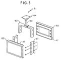
- FIG. 8 shows the case where two display panel assemblies 60 are suspended from the ceiling using a single suspension device 71.
- the suspension device 71 shown in FIG. 8 is different from the device 70 shown in FIG. 7A in that the rectangular shaped metal fittings 67 are used in place of the L-shaped metal fittings 61 shown in FIG. 7A.
- Two display panel assemblies 60 are attached to the metal fittings 67 using the metal fittings 47 on the backface thereof, and then the assembly 60 is attached to the hanger 62 using two fixing screws, respectively. Since the metal fitting 67 is not provided with the arch-shaped elongated holes, the shape of the metal fitting 67 should be appropriately formed so that the display panel assemblies 60 orient desired direction. This may be achieved by varying the width of the recessed portion of the metal fitting 67 so that the faces of the display panel assemblies 60 orient upwardly or downwardly, as desired.
- the second frame 21 is formed with the elongated fixing holes 23 elongated in its longitudinal direction. Therefore, the stress caused in attaching the second frame 21 does not affect the display panel 10 through the first frame 20 when the first frame 20 and the second frame 21 are fixed with each other.
- cylindrical elastic members 26 are interposed between the panel attachment frame 30 and the side attachment frame 27 or the lateral attachment frame 28, and hence the stress caused in attaching the assembly to the front casing is absorbed by the elastic member 26 and does not make any influence on the display panel device 10.
- the metal fittings 47 used in suspending the display panel assembly 60 from the ceiling is fixed to the side attachment frame 27 and the lateral attachment frame 28 via the rear casing 44, if the stress takes place when suspending the assembly 60, it does not make any influence to the front casing 40 and/or the rear casing 44 and to the display panel device 10 via the side attachment frame 27 and the lateral attachment frame 28. While the above description is directed to the case where the side attachment frames 27 and the front casing 40 are fixed together to the rear casing 44, it is also possible to fix the side attachment frames 27 to the front casing 40 by the fixing screws 46 and then the rear casing 44 is also fixed to the side attachment frames 27. This is advantageous in attaching the display panel assembly 60 to the wall by the metal fittings and the like.
- the cylindrical elastic member used in attaching the display panel device is not limited to the feature described and illustrated by referring to FIG. 4A, and may be configured as shown in FIG. 9A, wherein the bolt 80 is inserted into the cylindrical elastic member 26 having the laterally protruding section to fit with the nut 81.
- the cylindrical elastic member 26 may be provided with two annular grooves 26d and 26e in which the side attachment frame 27 (or the lateral attachment frame 28) and the lateral attachment frame 28 (or the side attachment frame 27) fit, and then the two frames are fixed by the bolt 80 and the nut 81.
- at least one of the surfaces of the annular grooves 26d and 26e, which contact one of the frames may be formed with the wave-like indentation to improve the elasticity.
- the frames described above may be formed by aluminum, for example.
- the elastic member 26 may be of other shape than the cylindrical shape.
Landscapes
- Physics & Mathematics (AREA)
- General Physics & Mathematics (AREA)
- Engineering & Computer Science (AREA)
- Theoretical Computer Science (AREA)
- Devices For Indicating Variable Information By Combining Individual Elements (AREA)
- Illuminated Signs And Luminous Advertising (AREA)
- Casings For Electric Apparatus (AREA)
Applications Claiming Priority (3)
| Application Number | Priority Date | Filing Date | Title |
|---|---|---|---|
| JP172800/97 | 1997-06-13 | ||
| JP17280097A JPH113041A (ja) | 1997-06-13 | 1997-06-13 | 表示パネルの取付装置 |
| JP17280097 | 1997-06-13 |
Publications (2)
| Publication Number | Publication Date |
|---|---|
| EP0884713A2 true EP0884713A2 (de) | 1998-12-16 |
| EP0884713A3 EP0884713A3 (de) | 2001-11-14 |
Family
ID=15948611
Family Applications (1)
| Application Number | Title | Priority Date | Filing Date |
|---|---|---|---|
| EP98110836A Withdrawn EP0884713A3 (de) | 1997-06-13 | 1998-06-12 | Befestigungsvorrichtung für Anzeigetafel |
Country Status (2)
| Country | Link |
|---|---|
| EP (1) | EP0884713A3 (de) |
| JP (1) | JPH113041A (de) |
Cited By (2)
| Publication number | Priority date | Publication date | Assignee | Title |
|---|---|---|---|---|
| EP1591870A2 (de) | 2004-04-27 | 2005-11-02 | Siemens Aktiengesellschaft | Stützelement und Anordnung zur Abstützung eines Displays gegen ein Gehäuse |
| US8599543B2 (en) | 2009-11-27 | 2013-12-03 | Canon Kabushiki Kaisha | Image display apparatus including connection structure for connection with supporting body |
Families Citing this family (6)
| Publication number | Priority date | Publication date | Assignee | Title |
|---|---|---|---|---|
| JP2005173509A (ja) * | 2003-12-15 | 2005-06-30 | Fujitsu Ltd | 電子装置 |
| JP5281819B2 (ja) * | 2008-04-28 | 2013-09-04 | シャープ株式会社 | 表示装置 |
| JP5317249B2 (ja) * | 2010-07-15 | 2013-10-16 | Necディスプレイソリューションズ株式会社 | フレーム筐体及び表示装置 |
| JP2010282217A (ja) * | 2010-07-26 | 2010-12-16 | Fujitsu Ltd | 電子装置 |
| JP6204325B2 (ja) * | 2014-11-07 | 2017-09-27 | 京セラドキュメントソリューションズ株式会社 | 画像走査ユニットの支持構造、画像形成装置 |
| JP7134143B2 (ja) * | 2019-06-28 | 2022-09-09 | 三菱電機株式会社 | 表示装置及びネジ固定構造 |
Family Cites Families (3)
| Publication number | Priority date | Publication date | Assignee | Title |
|---|---|---|---|---|
| EP0604893B1 (de) * | 1992-12-26 | 2002-05-02 | Canon Kabushiki Kaisha | Flüssigkristallapparat |
| JP3294053B2 (ja) * | 1995-05-19 | 2002-06-17 | 株式会社富士通ゼネラル | ディスプレイ装置 |
| JPH09149346A (ja) * | 1995-11-22 | 1997-06-06 | Fujitsu General Ltd | 表示器の破損ガラス破片飛散防止装置 |
-
1997
- 1997-06-13 JP JP17280097A patent/JPH113041A/ja active Pending
-
1998
- 1998-06-12 EP EP98110836A patent/EP0884713A3/de not_active Withdrawn
Cited By (3)
| Publication number | Priority date | Publication date | Assignee | Title |
|---|---|---|---|---|
| EP1591870A2 (de) | 2004-04-27 | 2005-11-02 | Siemens Aktiengesellschaft | Stützelement und Anordnung zur Abstützung eines Displays gegen ein Gehäuse |
| EP1591870A3 (de) * | 2004-04-27 | 2011-06-22 | Continental Automotive GmbH | Stützelement und Anordnung zur Abstützung eines Displays gegen ein Gehäuse |
| US8599543B2 (en) | 2009-11-27 | 2013-12-03 | Canon Kabushiki Kaisha | Image display apparatus including connection structure for connection with supporting body |
Also Published As
| Publication number | Publication date |
|---|---|
| EP0884713A3 (de) | 2001-11-14 |
| JPH113041A (ja) | 1999-01-06 |
Similar Documents
| Publication | Publication Date | Title |
|---|---|---|
| US6688576B2 (en) | Display apparatus | |
| US6791825B1 (en) | Tablet computer housing and method of construction | |
| EP0884713A2 (de) | Befestigungsvorrichtung für Anzeigetafel | |
| JPS61191786A (ja) | 密封式二重ガラス張りユニツト | |
| KR102209285B1 (ko) | 높이조절식 엘이디 디스플레이장치 | |
| CN115547203A (zh) | 承载箱体的拼装件和拼接显示装置 | |
| US20030136037A1 (en) | Advertisement light box | |
| US20250175116A1 (en) | Surface mount assemblies for a solar panel system | |
| JP2003227545A (ja) | 免震構造 | |
| JPH07212681A (ja) | 平面ディスプレイの据付装置 | |
| KR860001927B1 (ko) | 창 구조물 및 그 장착방법 | |
| US6581354B1 (en) | Glass curtain wall system | |
| US7006169B2 (en) | Display frame structure mounting arrangement | |
| JP5423100B2 (ja) | 画像表示装置 | |
| US8066234B2 (en) | Image display apparatus | |
| JP2003316274A (ja) | 平面ディスプレイ装置 | |
| US8599543B2 (en) | Image display apparatus including connection structure for connection with supporting body | |
| CN107725994B (zh) | 一种投影屏幕的安装调节组件及投影屏幕 | |
| CN223924359U (zh) | 调节装置及显示装置 | |
| CN211600131U (zh) | 一种用于安装显示设备的安装组件及显示组件 | |
| JP3904889B2 (ja) | ガラス板の支持構造および施工方法 | |
| JP3152382B2 (ja) | ガラス板の支持構造 | |
| CN213183420U (zh) | 一种户外led显示屏 | |
| CN121953186A (zh) | 拼接屏的安装支架及安装方法、显示装置 | |
| KR200347132Y1 (ko) | 평판 디스플레이용 지지대 |
Legal Events
| Date | Code | Title | Description |
|---|---|---|---|
| PUAI | Public reference made under article 153(3) epc to a published international application that has entered the european phase |
Free format text: ORIGINAL CODE: 0009012 |
|
| AK | Designated contracting states |
Kind code of ref document: A2 Designated state(s): AT BE CH CY DE DK ES FI FR GB GR IE IT LI LU MC NL PT SE Kind code of ref document: A2 Designated state(s): DE FR GB |
|
| AX | Request for extension of the european patent |
Free format text: AL;LT;LV;MK;RO;SI |
|
| PUAL | Search report despatched |
Free format text: ORIGINAL CODE: 0009013 |
|
| AK | Designated contracting states |
Kind code of ref document: A3 Designated state(s): AT BE CH CY DE DK ES FI FR GB GR IE IT LI LU MC NL PT SE |
|
| AX | Request for extension of the european patent |
Free format text: AL;LT;LV;MK;RO;SI |
|
| AKX | Designation fees paid |
Free format text: DE FR GB |
|
| STAA | Information on the status of an ep patent application or granted ep patent |
Free format text: STATUS: THE APPLICATION IS DEEMED TO BE WITHDRAWN |
|
| 18D | Application deemed to be withdrawn |
Effective date: 20020515 |