EP0884725A2 - Appareil d'enregistrement/reproduction magnétique - Google Patents
Appareil d'enregistrement/reproduction magnétique Download PDFInfo
- Publication number
- EP0884725A2 EP0884725A2 EP98304339A EP98304339A EP0884725A2 EP 0884725 A2 EP0884725 A2 EP 0884725A2 EP 98304339 A EP98304339 A EP 98304339A EP 98304339 A EP98304339 A EP 98304339A EP 0884725 A2 EP0884725 A2 EP 0884725A2
- Authority
- EP
- European Patent Office
- Prior art keywords
- cartridge
- slide member
- magnetic recording
- reproducing apparatus
- housing
- Prior art date
- Legal status (The legal status is an assumption and is not a legal conclusion. Google has not performed a legal analysis and makes no representation as to the accuracy of the status listed.)
- Granted
Links
- 230000033001 locomotion Effects 0.000 claims description 19
- 238000003780 insertion Methods 0.000 claims description 18
- 230000037431 insertion Effects 0.000 claims description 18
- 230000000694 effects Effects 0.000 abstract description 5
- 238000010276 construction Methods 0.000 description 7
- 238000004080 punching Methods 0.000 description 3
- 238000005452 bending Methods 0.000 description 2
- 230000000881 depressing effect Effects 0.000 description 1
- 230000000994 depressogenic effect Effects 0.000 description 1
- 230000006866 deterioration Effects 0.000 description 1
- 239000000428 dust Substances 0.000 description 1
- 238000000465 moulding Methods 0.000 description 1
- 230000002093 peripheral effect Effects 0.000 description 1
- 229910001220 stainless steel Inorganic materials 0.000 description 1
- 239000010935 stainless steel Substances 0.000 description 1
- 238000004804 winding Methods 0.000 description 1
Images






Classifications
-
- G—PHYSICS
- G11—INFORMATION STORAGE
- G11B—INFORMATION STORAGE BASED ON RELATIVE MOVEMENT BETWEEN RECORD CARRIER AND TRANSDUCER
- G11B33/00—Constructional parts, details or accessories not provided for in the other groups of this subclass
- G11B33/02—Cabinets; Cases; Stands; Disposition of apparatus therein or thereon
Definitions
- the present invention relates to a magnetic recording/reproducing apparatus. Particularly, the invention is concerned with a loading and unloading mechanism for a cartridge with a magnetic tape received therein.
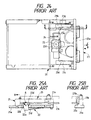
- FIG. 24 is a plan view of the apparatus
- FIG. 25A which is a sectional view taken on line A-A in FIG. 24, and
- FIG. 25B which is a side view of a principal portion thereof.
- a pair of guide members 21b and 21c each having a U-shaped groove are attached in an opposed relation to each other to right and left side faces of a base plate 21a.
- openings 21d are formed in portions of the base plate 21a, as shown in FIG. 25A.
- each plate spring 22 On the back of the base plate 21a are mounted a pair of plate springs 22 having a strong resilience, the plate springs 22 being screwed at one end thereof and free at the opposite end. At the tip of the free end of each plate spring 22 is formed a retaining portion 22a and a roller 22b is supported rotatably by the retaining portion 22a.
- the roller 22b is inserted into the associated opening 21d of the base plate 21a.
- the strong resilience of the plate spring 22 permits the roller 22b to move vertically within the opening 21d with the foregoing screwed portion of the plate spring as fulcrum.
- a cartridge 23, with a magnetic tape 23a accommodated therein, has guide grooves 23b formed in both side faces thereof, as shown in FIG. 25B.
- the guide grooves 23b are guided by the guide members 21b and 21c to conduct the cartridge 23 into the apparatus 21.
- the front end portion of the cartridge is inserted manually in the direction of arrow B from an inlet 21e of the apparatus.
- the operator For unloading the cartridge 23 from the apparatus 21, the operator is required to pull a rear end portion 23e of the cartridge, which projects from the inlet 21e to the exterior of the apparatus, manually in the direction of arrow C against the biasing force of the plate springs 22, allowing the rollers 22b to be disengaged from the cutout portions 23d of the cartridge 23, whereby the cartridge can be removed from the apparatus 21.
- a magnetic recording/reproducing apparatus including a loading and unloading mechanism which makes it possible for a cartridge with a magnetic tape received therein to be loaded and unloaded with respect to the apparatus, also including a slide member capable of engaging the cartridge, and further including a housing for holding the slide member, the loading and unloading of the cartridge being effected by sliding the slide member in an engaged state thereof with the cartridge.
- a magnetic recording/reproducing apparatus wherein the slide member is held slidably with respect to the housing and in such a manner that when the slide member lies on a cartridge inlet side, engaging portions thereof for engagement with the cartridge can be engaged with and disengaged from the cartridge in a direction orthogonal to the sliding direction.
- a magnetic recording/reproducing apparatus wherein the engagement of the slide member with the cartridge is effected by engagement of retaining portions formed as protuberances on the slide member side with engaging grooves formed on the cartridge side, the retaining portions of the slide member being displaceable vertically with respect to the sliding direction.
- a magnetic recording/reproducing apparatus wherein the retaining portions of the slide member are constituted by rollers supported on one end side of the slide member.
- a magnetic recording/reproducing apparatus wherein the slide member is formed with stoppers at positions near the rollers, the stoppers being higher than the rollers.
- a magnetic recording/reproducing apparatus wherein the housing is provided with cam portions to displace the slide member into engagement with and disengagement from the cartridge.
- a magnetic recording/reproducing apparatus wherein when the rollers are positioned on the lower side with a vertical motion of the slide member, the rollers come into contact with end portions of the engaging grooves of the cartridge to lock the cartridge temporarily.
- a magnetic recording/reproducing apparatus wherein the housing is provided with a drive source and a rotary cam mechanism connected to the drive source, and the slide member is driven electrically by the rotary cam mechanism.
- a magnetic recording/reproducing apparatus wherein in a cartridge loading position the whole of the cartridge is loaded completely into the housing.
- a magnetic recording/reproducing apparatus including a loading and unloading mechanism which makes it possible for a cartridge with a magnetic tape received therein to be loaded and unloaded with respect to the apparatus, also including a slide member capable of engaging the cartridge, further including an electric drive means for sliding the slide member, a housing for holding the slide member, and a sensor for detecting that the cartridge has been inserted into the housing, wherein when it is detected by the sensor that the cartridge has been inserted into the housing, the electric drive means is operated to start sliding of the slide member for completing the loading of the cartridge.
- a magnetic recording/reproducing apparatus wherein the housing is provided with a slidable opening member for opening a lid of the cartridge and wherein, after the cartridge has been inserted and its lid opened by the opening member, the opening member is allowed to slide with a further cartridge inserting motion, and this sliding of the opening member is detected by the sensor to detect that the cartridge has been inserted, whereupon the operation of the electric drive means is started.
- a magnetic recording/reproducing apparatus wherein an opening member for opening a lid of the cartridge is fixed to the housing and wherein, when it is detected by the sensor that the lid has been opened and that the cartridge has been inserted, the operation of the electric drive means is started.
- a magnetic recording/reproducing apparatus wherein the slide member is held slidably with respect to the housing and in such a manner that when the slide member lies on a cartridge inlet side, engaging portions thereof for engagement with the cartridge are movable in a direction orthogonal to the sliding direction.
- a magnetic recording/reproducing apparatus wherein the engagement of the slide member with the cartridge is effected by engagement of retaining portions constituted by rollers with engaging grooves formed in the cartridge, the said rollers being supported on one end side of the slide member and displaceable vertically with respect to the sliding direction.
- a magnetic recording/reproducing apparatus wherein the slide member is formed with stoppers at positions near the rollers, the stoppers being higher than the rollers.
- a magnetic recording/reproducing apparatus wherein the electric drive means comprises a motor and a transfer mechanism.
- a magnetic recording/reproducing apparatus including a loading and unloading mechanism which makes it possible for a cartridge with a magnetic tape received therein to be loaded and unloaded with respect to the apparatus, also including a slide member capable of engaging the cartridge, and further including a housing for holding the slide member, wherein the slide member is provided with a stopper mechanism for stopping the cartridge at a position of engagement with the slide member upon insertion of the cartridge into the apparatus and which stopper mechanism, when the slide member is pulled in, permits movement of the cartridge while maintaining the engaged state of the cartridge with the slide member.
- a magnetic recording/reproducing apparatus 1 substantially comprises a housing 2 which is generally rectangular in external shape and in the interior of which are mounted various components to be described later, and a cover 17 for closing an upper portion of the housing 2, with a cartridge inlet la being formed in a front portion of the housing.
- FIG. 2 is an appearance view at completed loading of the cartridge 4 into the apparatus 1 with the retaining portions of the slide member engaged in the grooves 4g.
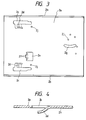
- the housing 2 is constituted by a metallic plate for example. As shown in a plan view of FIG. 3, the housing 2 is formed in a rectangular external shape and it comprises a bottom plate 2a and side plates 2b, 2b formed opposedly to each other by bending the bottom plate 2a upward (to this side perpendicularly to the paper surface of FIG. 3).
- portions of the housing 2 are projected to the back side of the bottom plate 2a to form the cam portions 2d as the above inclined portions integral with the housing.
- a head mounting hole 2e by punching.
- two stoppers 2f by cutting and raising portions of the bottom plate 2a upward (to this side perpendicularly to the paper surface of FIG. 3).
- an arcuate guide slot 2g is formed through the bottom plate 2a.
- Rivet mounting apertures 2j are formed in the bottom plate 2a at positions near the openings 2c, 2c and also near the guide slot 2g. Additionally, around the guide slot 2g are formed a plurality of circular apertures of a small diameter.
- the slide member 3 is disposed in contact with a back side 2h of the bottom plate 2a.
- the slide member 3 is constituted by a metallic plate having resilience such as a stainless steel plate. As shown in a perspective view of FIG. 5, the slide member 3 is generally U-shaped in external form and comprises a base portion 3a and arm portions 3b, 3c extending forward from both right and left sides of the base portion 3a.
- Tips of the arm portions 3b and 3c are bent upward at right angles from the outside to form a pair of roller holding portions 3d in an opposed relation to each other.
- Retaining portions are formed respectively at the tips of the paired roller holding portions 3d, 3d.
- the retaining portions are constituted respectively by metallic, retaining rollers 3e, 3e which are supported rotatably by shafts.
- elongated sliding slots 3f, 3f respectively by punching so that their longitudinal directions are parallel to each other.
- a sliding slot 3g by punching in a direction parallel to the sliding slots 3f.
- an elliptical aperture 3h is formed on the right-hand side of the sliding slot 3g in FIG. 5 in a direction orthogonal to the sliding slot 3g.
- the arm portions 3b and 3c are of the same length and their front ends 3j and 3k are formed in a rectilinear shape.
- the roller holding portions 3d, 3d extend forward beyond the front ends 3j and 3k.
- the slide member 3 of such a construction is mounted slidably to the back side 2h of the bottom plate 2a of the housing 2 with rivets 2K.
- the housing 2 shown in FIG. 3 is turned inside out so that the back side 2h faces up. Then, the roller holding portions 3d of the slide member 3 with the retaining rollers 3e attached thereto are aligned with the two openings 2c of the bottom plate 2a and inserted therein. Then, alignment is made so that the front ends 3j and 3k of the slide member 3 do not strike on the slants of the cam portions 2d of the bottom plate 2a.
- the three rivet mounting apertures 2j are aligned respectively with the sliding slots 3f, 3f and 3g formed in the slide member 3, and the tips of rivets 2k having head portions of a diameter larger than the width of each sliding slot are inserted into those sliding slots and rivet mounting apertures.
- the rivets 2k thus inserted into the rivet mounting apertures 2j of the housing 2 are then caulked and fixed to the bottom plate 2a with a caulking jig (not shown), whereby the slide member 3 is attached slidably to the back side 2h of the housing 2.
- the cartridge 4 to be loaded into the apparatus 1 receives therein a magnetic tape 4a, which is wound round rotatable reels 4b, 4b.
- a cutout portion 4j is formed centrally of a front side 4c of the cartridge 4, and a pinch roller 4d is disposed so that its outer peripheral portion partially overhangs the cutout portion 4j.
- the reels 4b, 4b rotate in interlock with rotation of the pinch roller 4d, thereby making it possible to wind up or wind back the magnetic tape 4a.
- guide portions 4e and 4f are formed guide portions 4e and 4f in an up-and-down relation to each other to guide the cartridge 4 into the apparatus 1.
- the right and left lower guide portions 4e respectively have engaging grooves 4g formed by partially cutting out the guide portions.
- a lid 4h capable of being opened and closed. With the lid 4h open, the magnetic tape 4a is exposed.
- a support pin 4m which supports the lid pivotably.
- a torsion coil spring (not shown) is wound round the support pin 4m to urge the lid 4h in its closing direction resiliently at all times.
- An end portion 4n of the lid 4h is projected on the right-hand side of the cartridge relative to the support pin 4m.
- the lid 4h turns around the support pin 4m to open the right-hand portion of the front side 4c of the cartridge 4.
- a motor mounting plate 5 is secured with bolts or the like to the bottom plate 2a of the housing 2, and an electric motor 6 for sliding the slide member 3 is mounted to the motor mounting plate 5. That is, the electric motor 6 is used as a drive source for sliding the slide member 3.
- a pinion gear 6a is mounted on the shaft of the motor 6 and the rotation of the motor is transmitted to gears 7via the pinion gear 6a.
- the gears 7 comprise a pinion gear 7a, a worm gear 7b integral with the pinion gear 7a, and pinion gears 7c, 7d each comprising two pinion gears of different diameters formed integrally with each other, which pinion gears and worm gear are in a mutually engaged state.
- the gears 7 thus constituted are fitted through respective shaft portions into apertures of a small diameter formed in the vicinity of the guide slot 2g.
- the cam mechanism 8 comprises a spur gear 9 and a cam plate 10.
- the spur gear 9 is circular in external form and has a plurality of tooth threads 9a formed on its outer periphery.
- the gear of a smaller diameter in the pinion gear 7d is in mesh with the tooth threads 9a to transmit the rotation of the motor 9 to the cam mechanism 8.
- a projection 9b of a generally triangular shape is formed on the surface of the spur gear 9 at a position close to the outer periphery of the surface.
- a cam groove 9c of a generally arcuate shape at predetermined width and depth in such a manner that the distance from the rotational center gradually becomes larger clockwise in FIG. 7A from near a central hole 9d up to near the tooth threads 9a formed on the outer periphery side.
- a rotatable cam plate 10 which converts the rotational motion of the spur gear 9 into a linear motion, is disposed between the spur gear 9 and the bottom plate 2a of the housing 2.
- the cam plate 10 has a generally L-shaped external form.
- a cam pin 10a of a circular section is projected upward at one end portion, and a support shaft 10b is projected downward at the rotational center of the cam plate.
- a slide pin 10c of a circular section is projected downward in the same direction as the support shaft 10b.
- the cam pin 10, support shaft 10b and slide pin 10c are secured to the cam plate 10 by caulking and the like.
- the support shaft 10b is attached rotatably to the bottom plate 2a, as shown in FIG. 9.
- the slide pin 10c of the cam plate 10 is fitted through the arcuate guide slot 2g movably and its tip is inserted into the elliptical aperture 3h formed in the slide member 3.
- the tip of the slide pin 10c projects downward through the aperture 3h and a washer (not shown) is caulked thereto.
- the slide member 3 is connected slidably to the tip of the slide pin 10c so as to prevent dislodgment thereof.
- the cam pin 10a is slidably engaged with the cam groove 9c of the spur gear 9.
- the cam plate 10 rotates counterclockwise about the support shaft 10b and the slide pin 10c moves in the arcuate guide slot 2g of the housing 2 in the direction of arrow E, causing the slide member 3 to slide in the arrow E direction.
- a magnetic head 11 is mounted within the head mounting hole 2e of the housing 2.
- a conveyance roller 12 for winding the magnetic tape 4a.
- the conveyance roller 12 is rotated clockwise and counterclockwise, thereby making it possible to wind up and wind back the magnetic tape 4a.
- the upper portion of the housing 2 is covered with a cover 17 to close the interior of the magnetic recording/reproducing apparatus 1.
- a cartridge inlet 1a In a front portion of the apparatus 1 is formed a cartridge inlet 1a, through which the cartridge 4 can be conducted smoothly into the apparatus.
- cartridge guide members for guiding the insertion of the cartridge 4 along the side plates 2b.
- an elongated opening member 13 for opening the lid 4h of the cartridge 4 is disposed slidably.
- the opening member 13 is formed by molding and the like. As shown in FIG. 15, a lid opening portion 13a is formed arcuately at an end portion of the opening member 13 so as to be positioned near the cartridge inlet 1a of the apparatus 1.
- the opening member 13 also has a pressing portion 13bprojecting upward on the right-hand side in the figure of the lid opening portion 13a.
- the pressing portion 13b is pressed by an end portion on the front side 4c of the cartridge, whereby the opening member 13 is made slidable.
- a coil spring retaining portion 13c On the right-hand side of the pressing portion 13b is formed a coil spring retaining portion 13c, and at a rightmost end in the figure is formed a switch input portion 13d as a lower stepped portion.
- a coil spring 14 is anchored at the coil spring retaining portion 13c of the opening member 13, while the opposite end thereof is fixed to the cartridge guide member (not shown). Consequently, the slidable opening member 13 is urged resiliently in the direction of arrow F at all times by virtue of the coil spring 14.
- a sensor 15 say, a push switch
- a printed circuit board 16 Above the switch input portion 13d formed on the right-hand side of the opening member 13, a sensor 15, say, a push switch, is secured to a printed circuit board 16.
- the switch input portion 13d pushes the detector 15 upward to turn ON the sensor, the sliding motion of the opening member 13 is detected by the sensor 15 and thus the insertion of the cartridge 4 can be detected.
- the printed circuit board 16 is mounted with bolts or the like to mounting portions (not shown) formed by cutting and bending the side plates 2b of the housing 2.
- the printed circuit board 16 is also covered with the cover 17.
- the front ends 3j (3k) of the slide member 3 strike on the slants of the cam portions 2d projecting from the bottom plate 2a of the housing 2. Further, the roller holding portions 3d sink downward and the retaining rollers 3e are positioned approximately half within the openings 2c.
- the front ends 3j (3k) of the slide member 3 are moved up and down by the cam portions 2d, whereby the retaining rollers 3e as the foregoing retaining portions can be engaged with and disengaged from the engaging grooves 4g of the cartridge 4.
- the retaining portions of the slide member for engagement with the cartridge are displaceable in a direction orthogonal to the sliding direction of the slide member.
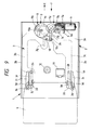
- the cartridge 4 which is indicated with a dash-double dot line in FIG. 9, is pushed in lightly in the direction of arrow E from the cartridge inlet la formed on the front side of the apparatus 1, by manual operation of the operator.
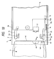
- the guide portions 4e and 4f formed on both right and left sides of the cartridge 4 are guided by the guide members disposed on both right and left sides in the interior of the housing 2, and the end portion 4n of the cartridge lid comes into abutment with the lid opening portion 13a of the opening member 13 in the interior of the housing 2, as shown in FIGS. 15 and 18.
- the end portion 4n of the lid 4 is pressed against the lid opening portion 13a of the opening member 13 and turns in the direction of arrow D in FIG. 18 with the support pin 4m as fulcrum, so that the front side 4c of the cartridge 4 is opened partially.
- the lid 4h assumes a forwardly straight state with respect to the front side 4c of the cartridge and thus becomes parallel to the opening member 13, as shown in FIG. 19.
- the opening member 13 moves, against the resilience of the coil spring 14, inwards together with the cartridge 4 and the switch input portion 13d of the opening member 13 turns ON the sensor 15 such as a push switch, attached to the printed circuit board 16 positioned above, to detect that the cartridge 4 has been inserted into the apparatus 1.
- the operation of the drive source 6 such as a motor for example is started.
- the relation between the retaining rollers 3e as the retaining portions of the slide member 3 and the engaging grooves 4g of the cartridge 4 is sudh that the retaining rollers 3e come to be positioned in the engaging grooves 4g from their state shown in FIG. 12 in which the retaining rollers strike on ends of the guide portions 4e.
- the insertion of the cartridge 4 gives rise to a click feeling.
- the senor 15 is turned ON and the operation for inserting the cartridge 4 into the apparatus 1 is switched over from manual operation to electric drive using the drive source 6 such as a motor for example.
- the top of the apex of the triangular projection 9b of the spur gear turns ON a slide position detecting switch (not shown) which is provided on the printed circuit board 16 located above the spur gear and which is for detecting a slide position in the loading direction, with the result that the drive source 6 turns OFF.
- the pin 10a on the cam plate 10 engaged in the cam groove 9c of the spur gear 9 is positioned approximately on the outermost periphery side, and the pin 10c, which is in an engagement anti-dislodgmentwise with the slide member 3, moves up to the outermost side in the arrow E direction of the guide slot 2g of the housing 2.
- the cartridge 4 comes into abutment with the conveyance roller 12 and its sliding motion stops.
- the slide member 3 moves a little more in the arrow E direction and then stops in order to prevent slippage with respect to the pinch roller.
- the retaining rollers 3e of the slide member 3 somewhat strike on the side walls of the guide portions 4e with the engaging grooves 4g formed therein and are located at lower positions to retain the cartridge 4.
- recording and reproduction for the magnetic tape 4a can be done any time in accordance with a command issued from an external computer (not shown) for example.
- the cartridge 4 can be loaded into the apparatus 1 and positioned and held therein.
- the drive source 6 is turned ON and is rotated in the direction opposite to the rotational direction in the loading of the cartridge 4, thereby causing the spur gear 9 to rotate clockwise from its state shown in FIG. 10.
- cam plate 10 is rotated clockwise and the pin 10c is moved in the arrow F direction, thus causing the slide member 3 to slide toward the cartridge inlet la (in the arrow F direction).
- the slide member 3 and the cartridge 4 are returned to their positions shown in FIGS. 9 and 12.
- the apex of the triangular projection 9b of the spur gear 9 turns ON a slide position detecting switch (not shown) which is provided on the printed circuit board 16 and which is for detecting a slide position in the eject direction, resulting in that the rotation of the drive source 6 is stopped to stop the movement in the arrow F direction of the slide member 3.
- the cartridge 4 moves to the front side of the apparatus 1 relative to the position where the sensor 15 turns ON, with the resilience of the coil spring 14 which is anchored at the opening member -13.
- the retaining rollers 3e of the slide member 3 are in a temporarily engaged state in the engaging grooves 4g of the cartridge 4, as shown in FIG. 12, so that the cartridge can be easily taken out from the apparatus 1 manually and with a light force.
- the apparatus 1 Upon completion of the cartridge extracting operation, the apparatus 1 assumes a stand-by state waiting for insertion of the cartridge 4.
- the motor 6 as the drive source or the cam mechanism 8 fails during the cartridge eject operation from the apparatus 1 and the cartridge 4 is left behind within the apparatus, the operator is required to pull out the cartridge while holding a rear side 4K of the cartridge, whereby the holding portions 3d are deflected downward and hence the cartridge can be taken out.
- the cartridge 4 is employable without any trouble.
- a resilient member for urging the cartridge 4 in a direction to eject it to the exterior of the apparatus 1 is provided separately and the cartridge is ejected by the resilient member, it is possible to further improve the operability.
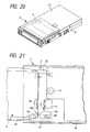
- FIG. 20 there is illustrated another embodiment of the present invention, in which the whole of the cartridge 4 is loaded completely into the housing 2.
- the cartridge 4 there is no portion of the cartridge 4 projecting from the apparatus 1 to the exterior and therefore there is no fear of, for example, the operator's hand striking against the cartridge by mistake which would cause a deviation in the abutment position between the tape and the head.
- the cartridge may be left loaded in the apparatus over a long period. Even in such a case, this embodiment permits suppressing the deterioration of performance caused by the entry of dust or the like. Thus, it is possible to effect recording and reproduction with a high reliability.
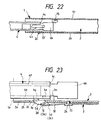
- FIGS. 21 and 22 there is illustrated a further embodiment of the present invention in which the body of a cartridge is detected directly and then the loading of the cartridge is started.
- an opening member 13' is formed integrally with a cartridge guide member (not shown) which is fixed in the interior of the housing 2 to guide the insertion of a cartridge 4.
- a sensor 15 is attached to the opening member 13' in an opposed relation to an opening position of a lid 4h of the cartridge 4.
- the surface of the lid 4h pushes ON the sensor 15 attached to the opening member 13 and constituted by a push switch or the like, whereby it is detected that the cartridge 4 has been inserted into the apparatus. Then, a drive source 6 such as a motor is turned ON.
- the sensor 15 may be attached to an upper case 17 or printed circuit board 16, as shown in FIG. 22. According to this construction, when the cartridge 4 is further inserted into the apparatus 1 after the lid 4h has been opened by the opening member 13', an upper end portion of the lid 4h pushes ON the sensor 15.
- the senor is provided correspondingly to the lid opening position of the cartridge, it is possible to surely detect insertion of the cartridge and opening of the lid without using any other separate member.
- FIG. 23 a description is directed to a magnetic recording/reproducing apparatus according to a still further embodiment of the present invention which apparatus is provided with stoppers for preventing the overrun of a cartridge at the time of insertion of the cartridge.
- a slide member 3 is integrally forined with stopper portions 3m by press working so as to be located at a more inside position than roller holding portions 3d and higher than retaining rollers 3e of the slide member 3.
- the stopper portions 3m are formed so that they can stop insertion of a cartridge 4 at a position where the retaining rollers 3e are engaged in retaining grooves 4g of the cartridge 4.
- the slide member since the slide member is brought into engagement with engaging portions of a cartridge, allowing the cartridge to slide and be loaded to and ejected from the apparatus with sliding motions of the slide member, the cartridge can be loaded to and ejected from a recording/reproducing position of the apparatus easily and securely.
Landscapes
- Feeding And Guiding Record Carriers (AREA)
Applications Claiming Priority (9)
| Application Number | Priority Date | Filing Date | Title |
|---|---|---|---|
| JP15222097 | 1997-06-10 | ||
| JP152220/97 | 1997-06-10 | ||
| JP9152220A JPH10340508A (ja) | 1997-06-10 | 1997-06-10 | 磁気記録再生装置 |
| JP159686/97 | 1997-06-17 | ||
| JP15968597A JP3431453B2 (ja) | 1997-06-17 | 1997-06-17 | 磁気記録再生装置 |
| JP15968697 | 1997-06-17 | ||
| JP159685/97 | 1997-06-17 | ||
| JP15968597 | 1997-06-17 | ||
| JP15968697A JP3455064B2 (ja) | 1997-06-17 | 1997-06-17 | 磁気記録再生装置 |
Publications (3)
| Publication Number | Publication Date |
|---|---|
| EP0884725A2 true EP0884725A2 (fr) | 1998-12-16 |
| EP0884725A3 EP0884725A3 (fr) | 1999-02-03 |
| EP0884725B1 EP0884725B1 (fr) | 2003-05-07 |
Family
ID=27320240
Family Applications (1)
| Application Number | Title | Priority Date | Filing Date |
|---|---|---|---|
| EP98304339A Expired - Lifetime EP0884725B1 (fr) | 1997-06-10 | 1998-06-02 | Appareil d'enregistrement/reproduction magnétique |
Country Status (3)
| Country | Link |
|---|---|
| US (1) | US6201660B1 (fr) |
| EP (1) | EP0884725B1 (fr) |
| DE (1) | DE69814233T2 (fr) |
Cited By (5)
| Publication number | Priority date | Publication date | Assignee | Title |
|---|---|---|---|---|
| WO2000016324A1 (fr) * | 1998-09-10 | 2000-03-23 | Onstream, Inc. | Appareil d'ecriture et/ou lecture d'informations |
| GB2352865A (en) * | 1999-05-17 | 2001-02-07 | Hewlett Packard Co | Picker indexing and multimedia cartridge referencing spring |
| US6621654B2 (en) | 2001-02-22 | 2003-09-16 | Hewlett-Packard Development Company, L.P. | Apparatus and method for retaining different sizes of data cartridges in a storage magazine |
| EP1288934A3 (fr) * | 2001-08-23 | 2003-12-03 | Hewlett-Packard Company | Système et procédé pour retenir les support de données dans un système de stockage |
| US7006319B2 (en) | 2003-03-27 | 2006-02-28 | Hewlett-Packard Development Company, L.P. | Media-detection system and method for identifying types of data cartridges |
Family Cites Families (13)
| Publication number | Priority date | Publication date | Assignee | Title |
|---|---|---|---|---|
| US5272579A (en) * | 1988-11-08 | 1993-12-21 | Teac Corporation | Mechanism for loading tape cartridge into tape driving apparatus |
| US5109308A (en) * | 1989-04-25 | 1992-04-28 | Archive Corporation | Stationary head tape drive with a movable door opening mechanism |
| US5025334A (en) * | 1989-09-12 | 1991-06-18 | Cipher Data Products, Inc. | Auto-loading transport for tape cartridge with tape access door and belt capstan roller |
| EP0562390A3 (en) * | 1992-03-27 | 1994-11-17 | Wangtek Inc | Magnetic tape cartridge drive with automatic pre-loading |
| US5236146A (en) | 1992-04-15 | 1993-08-17 | Tandberg Data A/S | Capstan belt drive |
| US5371642A (en) * | 1992-11-13 | 1994-12-06 | Wangtek | Tape drive assembly with an automatic door opening/closing mechanism |
| DE69316742T2 (de) | 1993-07-08 | 1998-05-14 | Tandberg Data | Motoraufhängung für Antriebsrolle |
| US5373406A (en) * | 1993-08-12 | 1994-12-13 | Tandberg Data A/S | Auto load/eject system for tape cassette |
| JPH0798909A (ja) * | 1993-09-30 | 1995-04-11 | Teac Corp | 磁気記録再生装置 |
| JPH10504672A (ja) | 1994-06-09 | 1998-05-06 | コナー ペリフェラルズ インコーポレイテッド | テープドライブの内部でテープを動かすための機構 |
| US5568340A (en) * | 1994-12-28 | 1996-10-22 | Industrial Technology Research Institute | Cassette loading and unloading device |
| US5557485A (en) | 1995-03-31 | 1996-09-17 | Hewlett-Packard Company | Alignment and latching mechanism in a drive for magnetic data tape mini-cartridges |
| US6016236A (en) * | 1996-10-21 | 2000-01-18 | Onstream, Inc. | Apparatus for the storage and/or reproduction of information on/from an information carrier |
-
1998
- 1998-06-02 DE DE69814233T patent/DE69814233T2/de not_active Expired - Fee Related
- 1998-06-02 EP EP98304339A patent/EP0884725B1/fr not_active Expired - Lifetime
- 1998-06-09 US US09/094,063 patent/US6201660B1/en not_active Expired - Fee Related
Cited By (8)
| Publication number | Priority date | Publication date | Assignee | Title |
|---|---|---|---|---|
| WO2000016324A1 (fr) * | 1998-09-10 | 2000-03-23 | Onstream, Inc. | Appareil d'ecriture et/ou lecture d'informations |
| GB2352865A (en) * | 1999-05-17 | 2001-02-07 | Hewlett Packard Co | Picker indexing and multimedia cartridge referencing spring |
| US6259579B1 (en) | 1999-05-17 | 2001-07-10 | Hewlett-Packard Company | Picker indexing and multimedia cartridge referencing spring |
| GB2352865B (en) * | 1999-05-17 | 2003-10-29 | Hewlett Packard Co | Picker indexing and multimedia cartridge referencing spring |
| US6621654B2 (en) | 2001-02-22 | 2003-09-16 | Hewlett-Packard Development Company, L.P. | Apparatus and method for retaining different sizes of data cartridges in a storage magazine |
| EP1288934A3 (fr) * | 2001-08-23 | 2003-12-03 | Hewlett-Packard Company | Système et procédé pour retenir les support de données dans un système de stockage |
| US6804877B2 (en) | 2001-08-23 | 2004-10-19 | Hewlett-Packard Development Company, L.P. | Methods for attaching a spring mechanism to a media storage device |
| US7006319B2 (en) | 2003-03-27 | 2006-02-28 | Hewlett-Packard Development Company, L.P. | Media-detection system and method for identifying types of data cartridges |
Also Published As
| Publication number | Publication date |
|---|---|
| DE69814233D1 (de) | 2003-06-12 |
| EP0884725A3 (fr) | 1999-02-03 |
| US6201660B1 (en) | 2001-03-13 |
| DE69814233T2 (de) | 2003-11-20 |
| EP0884725B1 (fr) | 2003-05-07 |
Similar Documents
| Publication | Publication Date | Title |
|---|---|---|
| EP0884725B1 (fr) | Appareil d'enregistrement/reproduction magnétique | |
| US4763212A (en) | Floppy disk drive with a linearly operated media clamp | |
| US5764433A (en) | Short-side-loading tape cassette recording and/or reproducing apparatus | |
| JPS6231061A (ja) | フロツピ−デイスク装置 | |
| JP3455064B2 (ja) | 磁気記録再生装置 | |
| JP3431453B2 (ja) | 磁気記録再生装置 | |
| EP0855707B1 (fr) | Appareil à disque | |
| US6188541B1 (en) | Magnetic recording-reproducing device | |
| JP3835340B2 (ja) | 光ディスク装置 | |
| EP0892402B1 (fr) | Procédé de fonctionnement d'appareil d'enregistrement et de reproduction magnétique | |
| JP3105026B2 (ja) | ディスクカートリッジのシャッタ開閉機構 | |
| JP3610224B2 (ja) | 磁気記録再生装置 | |
| US20030102371A1 (en) | Card connecting unit provided with loading mechanism | |
| JPH10340508A (ja) | 磁気記録再生装置 | |
| JPH0237134Y2 (fr) | ||
| JP3642089B2 (ja) | 磁気ディスクドライバ | |
| JP3589252B2 (ja) | 磁気記録再生装置のヘッド移送機構 | |
| JP3105198B2 (ja) | ディスクカートリッジのシャッタ開閉機構 | |
| JP2816278B2 (ja) | フレキシブルディスク装置 | |
| JPH0249009Y2 (fr) | ||
| JPH09207094A (ja) | テープ印字装置のカッタ機構 | |
| JPH08203182A (ja) | ディスクカートリッジローディング装置 | |
| JPH05109169A (ja) | フレキシブルデイスク駆動装置 | |
| JPH11224449A (ja) | 磁気記録再生装置 | |
| JPH0726937U (ja) | 磁気ディスク駆動装置 |
Legal Events
| Date | Code | Title | Description |
|---|---|---|---|
| PUAI | Public reference made under article 153(3) epc to a published international application that has entered the european phase |
Free format text: ORIGINAL CODE: 0009012 |
|
| AK | Designated contracting states |
Kind code of ref document: A2 Designated state(s): DE FR GB |
|
| AX | Request for extension of the european patent |
Free format text: AL;LT;LV;MK;RO;SI |
|
| PUAL | Search report despatched |
Free format text: ORIGINAL CODE: 0009013 |
|
| AK | Designated contracting states |
Kind code of ref document: A3 Designated state(s): AT BE CH CY DE DK ES FI FR GB GR IE IT LI LU MC NL PT SE |
|
| AX | Request for extension of the european patent |
Free format text: AL;LT;LV;MK;RO;SI |
|
| 17P | Request for examination filed |
Effective date: 19990213 |
|
| AKX | Designation fees paid |
Free format text: DE FR GB |
|
| 17Q | First examination report despatched |
Effective date: 20010213 |
|
| GRAH | Despatch of communication of intention to grant a patent |
Free format text: ORIGINAL CODE: EPIDOS IGRA |
|
| GRAH | Despatch of communication of intention to grant a patent |
Free format text: ORIGINAL CODE: EPIDOS IGRA |
|
| GRAA | (expected) grant |
Free format text: ORIGINAL CODE: 0009210 |
|
| AK | Designated contracting states |
Designated state(s): DE FR GB |
|
| REG | Reference to a national code |
Ref country code: GB Ref legal event code: FG4D |
|
| REF | Corresponds to: |
Ref document number: 69814233 Country of ref document: DE Date of ref document: 20030612 Kind code of ref document: P |
|
| ET | Fr: translation filed | ||
| PLBE | No opposition filed within time limit |
Free format text: ORIGINAL CODE: 0009261 |
|
| STAA | Information on the status of an ep patent application or granted ep patent |
Free format text: STATUS: NO OPPOSITION FILED WITHIN TIME LIMIT |
|
| 26N | No opposition filed |
Effective date: 20040210 |
|
| PGFP | Annual fee paid to national office [announced via postgrant information from national office to epo] |
Ref country code: GB Payment date: 20050512 Year of fee payment: 8 |
|
| PGFP | Annual fee paid to national office [announced via postgrant information from national office to epo] |
Ref country code: FR Payment date: 20050519 Year of fee payment: 8 |
|
| PGFP | Annual fee paid to national office [announced via postgrant information from national office to epo] |
Ref country code: DE Payment date: 20050822 Year of fee payment: 8 |
|
| PG25 | Lapsed in a contracting state [announced via postgrant information from national office to epo] |
Ref country code: GB Free format text: LAPSE BECAUSE OF NON-PAYMENT OF DUE FEES Effective date: 20060602 |
|
| PG25 | Lapsed in a contracting state [announced via postgrant information from national office to epo] |
Ref country code: DE Free format text: LAPSE BECAUSE OF NON-PAYMENT OF DUE FEES Effective date: 20070103 |
|
| GBPC | Gb: european patent ceased through non-payment of renewal fee |
Effective date: 20060602 |
|
| REG | Reference to a national code |
Ref country code: FR Ref legal event code: ST Effective date: 20070228 |
|
| PG25 | Lapsed in a contracting state [announced via postgrant information from national office to epo] |
Ref country code: FR Free format text: LAPSE BECAUSE OF NON-PAYMENT OF DUE FEES Effective date: 20060630 |