EP0884745A1 - Leistungsschalter mit einem Einschaltwiderstand - Google Patents
Leistungsschalter mit einem Einschaltwiderstand Download PDFInfo
- Publication number
- EP0884745A1 EP0884745A1 EP98401355A EP98401355A EP0884745A1 EP 0884745 A1 EP0884745 A1 EP 0884745A1 EP 98401355 A EP98401355 A EP 98401355A EP 98401355 A EP98401355 A EP 98401355A EP 0884745 A1 EP0884745 A1 EP 0884745A1
- Authority
- EP
- European Patent Office
- Prior art keywords
- contacts
- circuit breaker
- semi
- closing
- arcing
- Prior art date
- Legal status (The legal status is an assumption and is not a legal conclusion. Google has not performed a legal analysis and makes no representation as to the accuracy of the status listed.)
- Granted
Links
- 238000003780 insertion Methods 0.000 claims description 11
- 230000037431 insertion Effects 0.000 claims description 11
- 238000007664 blowing Methods 0.000 claims description 8
- 230000006835 compression Effects 0.000 claims description 5
- 238000007906 compression Methods 0.000 claims description 5
- 230000003111 delayed effect Effects 0.000 claims description 3
- 238000013022 venting Methods 0.000 abstract 1
- 238000006073 displacement reaction Methods 0.000 description 6
- 238000010891 electric arc Methods 0.000 description 4
- 239000002184 metal Substances 0.000 description 4
- 241000722921 Tulipa gesneriana Species 0.000 description 3
- 230000002040 relaxant effect Effects 0.000 description 2
- 230000035939 shock Effects 0.000 description 2
- 238000010276 construction Methods 0.000 description 1
- 230000007423 decrease Effects 0.000 description 1
- 230000000694 effects Effects 0.000 description 1
- 229910052573 porcelain Inorganic materials 0.000 description 1
- 238000000926 separation method Methods 0.000 description 1
Images



Classifications
-
- H—ELECTRICITY
- H01—ELECTRIC ELEMENTS
- H01H—ELECTRIC SWITCHES; RELAYS; SELECTORS; EMERGENCY PROTECTIVE DEVICES
- H01H33/00—High-tension or heavy-current switches with arc-extinguishing or arc-preventing means
- H01H33/02—Details
- H01H33/04—Means for extinguishing or preventing arc between current-carrying parts
- H01H33/16—Impedances connected with contacts
- H01H33/166—Impedances connected with contacts the impedance being inserted only while closing the switch
Definitions
- the invention relates to a circuit breaker comprising a first contact permanent and a first arcing contact fixedly mounted in an enclosure, a second permanent contact and a second arcing contact mounted mobile in the envelope in a certain longitudinal direction and intended to cooperate with the first fixed contacts and a resistor insertion system closing, the second movable contacts being part of a crew carrying a blowing nozzle.
- the object of the invention is to propose a system for inserting the closing resistance for such a circuit breaker which is of a simple design and which allows to obtain a good compactness of the assembly with a minimum moving parts.
- the invention relates to such a circuit breaker characterized in that that said closing resistance insertion system comprises a block semi-mobile which is arranged to be moved, during a closing operation, by the blowing nozzle in said longitudinal direction and which carries a third arcing contact intended to cooperate with a fourth fixed arcing contact connected to the fixed permanent contact, this semi-mobile block by its displacement, bringing the third and fourth arcing contacts together to short-circuit this closing resistance while said first and second arcing contacts are connected to each other and that the permanent contacts are separated from each other, these permanent contacts being connected to each other only after the third and fourth arcing contacts are themselves connected to each other.
- the semi-mobile block has a conical end which fits into the blowing nozzle in the shape of a tulip during the closing operation of the circuit breaker.
- the effects of the shock between the nozzle and the block are eliminated.
- semi-mobile when they come into contact with each other and we get a displacement speed of the semi-mobile unit identical to that of the first movable contacts when the circuit breaker closes.
- the semi-mobile block has a tubular shape and has a spring which is compressed on closing of the circuit breaker and a chamber that fills with gas during this closing operation so that when the circuit breaker opens, the spring by relaxing automatically moves the semi-movable block in the direction of movement of the first arcing contacts and permanent to separate the third and fourth arcing contacts.
- the displacement of this semi-mobile block the opening of the circuit breaker is delayed and slowed down compared to displacement of the first arcing contacts and permanent because the spring relaxation is accompanied by a necessary evacuation of gas from the chamber by calibrated openings.
- circuit breaker An exemplary embodiment of the circuit breaker according to the invention is described below in more detail and illustrated in the drawings.
- Figure 1 very schematically shows a circuit breaker according to the invention in the fully open position.
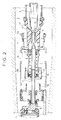
- Figure 2 very schematically shows the circuit breaker of Figure 1 in a first intermediate closed position.
- Figure 3 shows very schematically the circuit breaker of Figure 1 in a second intermediate closed position.
- Figure 4 very schematically shows the circuit breaker of Figure 1 in a fully closed position.
- Figure 5 shows very schematically the circuit breaker of Figure 1 in a first intermediate opening position.
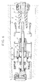
- Figure 6 shows very schematically the circuit breaker of Figure 1 in a second intermediate open position.
- the circuit breaker partially shown in the figures includes a insulating casing 1 of cylindrical shape, for example of porcelain, which delimits an interior volume 2 intended to be filled with a dielectric gas as SF6 under a pressure of a few bars.
- This circuit breaker is a single movement circuit breaker, i.e. with a single movable equipment of arcing and permanent contacts, and includes a insertion system of a closing resistor whose arrangement allows simply control the duration of insertion of the closing resistance of the circuit breaker, this resistor should not be inserted when the circuit breaker.
- the closing resistor 4 consists of a stack of resistors housed in an insulating support 5 placed inside the enclosure to one end of it. Closing resistor 4 is in electrical contact with a metal block 6 on which is fixed a metal rod 7 which extends axially in the envelope. In the embodiment shown in the figures, the closing resistor 4 extends axially in the envelope but one could also provide an eccentric arrangement of this resistance in the envelope without departing from the scope of the invention.
- the fixed arcing contact 8 is disposed at the free end of the rod 7.
- the fixed permanent contact 9 is arranged at one end of a metal tube 9A arranged coaxially around the rod 7.
- An insulating cone 10 is provided so optional to hold the rod 7 inside the tube 9A.
- the closing resistor 4 insertion system comprises a block semi-mobile metallic 14 of tubular shape which is mounted to be able slide on the rod 7, that is to say along the axis 3.
- This semi-mobile block 14 is electrically connected to the rod 7 by sliding contacts 17. It carries a arcing contact 15 subsequently called first switching contact in the form of tulip which is intended to cooperate with another arcing contact 16 in the form ring (hereinafter called second switching contact) disposed at inside the cylindrical tube 9A and electrically connected thereto.
- the arrangement of the resistance insertion system is essentially arranged axially in the envelope which can therefore have a relatively small diameter.
- the semi-mobile block 14 has one end, which faces the blowing nozzle 13, cone-shaped adapted to come fit into the nozzle.
- the other end face (left face on the figures) of the semi-mobile block 14 closes behind a compression piston 18 which is constituted by a crown secured to the rod 7.
- a spring 20 is mounted between the piston 18 and a shoulder located at rear of the conical end of the semi-movable block.
- the space defined between this piston and this other end face constitutes a chamber 19 with volume variable.
- Chamber 19 in the semi-mobile block communicates with the volume inside the tube 9A through openings 21.
- FIG. 1 the circuit breaker is in the fully open position.
- the fixed contacts 8 and 9 are separated from mobile contacts 11 and 12.
- Contact 15 is separated from contact 16.
- the spring 20 in the semi-movable block is completely relaxed and the space between the piston 18 and the left face of the semi-mobile block is minimum.
- the arcing contacts 8 and 11 are less distant by construction from each other than permanent contacts 9 and 12 ce which means that when the circuit breaker closes, the contacts 8 and 11 are connected mutually before contacts 9 and 12.
- the contacts of switching 15 and 16 are distant from each other by a distance such that these contacts connect to each other after connecting the arcing contacts but before the connection of the permanent contacts which allows control, via the displacement of the semi-mobile block, the duration of the insertion of the resistor 4 at the closing as we will see later.
- the chamber 19 is filled gas passing through the openings 21.
- the arcing contacts 8 and 11 are connected to each other while the switching contacts 15 and 16 are just close enough to each other to that an electric arc 22 can be created between them without an electric arc can be created between permanent contacts 9 and 12. Indeed, the latter are at this time distant from each other by a greater distance than that separating the switching contacts.
- the closing resistance 4 is short-circuited since the current flows between the arcing contacts 11 and 8, in the rod 7, in the sliding contacts 17, in the semi-mobile block 14, in switching contact 15, in switching contact 16 and in the tube 9A.
- the movable contacts 11 and 12 are move from left to right in the figures. Permanent contacts 9 and 12 separate first from each other, then then the arcing contacts 8 and 11 but the switching contacts 15 and 16 always remain connected for some time to each other as shown in Figures 5 and 6 because the block semi-mobile moves more slowly than mobile contacts. In fact, the block semi-mobile moves from left to right in the figures by the action of the spring 20 which exerts a restoring force by relaxing against the piston 18.
- the relaxation of the spring 20 is delayed and slowed down by the fact that a force opposite of resistance opposes the restoring force exerted by the spring, this contrary force resulting from the necessary compression of gas in the chamber 19 whose volume decreases as the semi-movable block moves because the gas exhaust openings in this chamber are calibrated so adequate.
- This calibration is such that the switching contacts 15 and 16 are only separate from each other after complete separation of the contacts arc. In this way, the short-circuit current cannot pass through the closing resistance 4 when opening the circuit breaker. It's only when the electric arc created between the arcing contacts is blown out in particular that the semi-mobile block 14 finishes its race to separate the contacts 15 and 16 and return to its initial position illustrated in FIG. 1.
Landscapes
- Circuit Breakers (AREA)
- Arc-Extinguishing Devices That Are Switches (AREA)
- Driving Mechanisms And Operating Circuits Of Arc-Extinguishing High-Tension Switches (AREA)
- Refuge Islands, Traffic Blockers, Or Guard Fence (AREA)
- Keying Circuit Devices (AREA)
- Cookers (AREA)
Applications Claiming Priority (2)
| Application Number | Priority Date | Filing Date | Title |
|---|---|---|---|
| FR9707284A FR2764728B1 (fr) | 1997-06-12 | 1997-06-12 | Disjoncteur a resistance de fermeture |
| FR9707284 | 1997-06-12 |
Publications (2)
| Publication Number | Publication Date |
|---|---|
| EP0884745A1 true EP0884745A1 (de) | 1998-12-16 |
| EP0884745B1 EP0884745B1 (de) | 2004-03-17 |
Family
ID=9507893
Family Applications (1)
| Application Number | Title | Priority Date | Filing Date |
|---|---|---|---|
| EP98401355A Expired - Lifetime EP0884745B1 (de) | 1997-06-12 | 1998-06-08 | Leistungsschalter mit einem Einschaltwiderstand |
Country Status (9)
| Country | Link |
|---|---|
| US (1) | US5955715A (de) |
| EP (1) | EP0884745B1 (de) |
| CN (1) | CN1089939C (de) |
| AT (1) | ATE262216T1 (de) |
| BR (1) | BR9802002A (de) |
| CA (1) | CA2239239C (de) |
| DE (1) | DE69822369T2 (de) |
| FR (1) | FR2764728B1 (de) |
| RU (1) | RU2157016C2 (de) |
Families Citing this family (6)
| Publication number | Priority date | Publication date | Assignee | Title |
|---|---|---|---|---|
| FR2887070B1 (fr) * | 2005-06-10 | 2008-11-07 | Areva T & D Ag | Commutateur electrique comportant un contact fixe annulaire |
| DE502007004867D1 (de) * | 2007-09-10 | 2010-10-07 | Abb Technology Ag | Einschaltwiderstand für Hochspannungsleistungsschalter |
| FR2922354B1 (fr) * | 2007-10-15 | 2009-12-11 | Areva T & D Sa | Disjoncteur a deux chambres de coupure alignees, a transmission commune et encombrement reduit |
| CN101409176B (zh) * | 2008-12-04 | 2011-12-07 | 天水长城开关厂有限公司 | 一种真空断路器用主回路结构 |
| US9305726B2 (en) * | 2014-08-27 | 2016-04-05 | Eaton Corporation | Arc extinguishing contact assembly for a circuit breaker assembly |
| CN109872885A (zh) * | 2017-12-04 | 2019-06-11 | 江苏大全封闭母线有限公司 | 一种动静触头插拔限位机构 |
Citations (1)
| Publication number | Priority date | Publication date | Assignee | Title |
|---|---|---|---|---|
| DE3411445A1 (de) * | 1984-02-06 | 1985-08-08 | BBC Aktiengesellschaft Brown, Boveri & Cie., Baden, Aargau | Hochspannungsschalter |
Family Cites Families (3)
| Publication number | Priority date | Publication date | Assignee | Title |
|---|---|---|---|---|
| FR2596575B1 (fr) * | 1986-03-26 | 1988-05-20 | Alsthom | Disjoncteur a gaz dielectrique sous pression |
| FR2629260B1 (fr) * | 1988-03-23 | 1994-07-08 | Alsthom | Disjoncteur a haute tension a faible energie de manoeuvre |
| FR2657459A1 (fr) * | 1990-01-19 | 1991-07-26 | Alsthom Gec | Disjoncteur a haute tension a resistance de fermeture. |
-
1997
- 1997-06-12 FR FR9707284A patent/FR2764728B1/fr not_active Expired - Fee Related
-
1998
- 1998-06-08 DE DE69822369T patent/DE69822369T2/de not_active Expired - Lifetime
- 1998-06-08 AT AT98401355T patent/ATE262216T1/de not_active IP Right Cessation
- 1998-06-08 EP EP98401355A patent/EP0884745B1/de not_active Expired - Lifetime
- 1998-06-11 CA CA002239239A patent/CA2239239C/fr not_active Expired - Fee Related
- 1998-06-11 US US09/095,713 patent/US5955715A/en not_active Expired - Lifetime
- 1998-06-11 RU RU98111066/09A patent/RU2157016C2/ru not_active IP Right Cessation
- 1998-06-12 CN CN98114759A patent/CN1089939C/zh not_active Expired - Lifetime
- 1998-06-12 BR BR9802002-1A patent/BR9802002A/pt not_active IP Right Cessation
Patent Citations (1)
| Publication number | Priority date | Publication date | Assignee | Title |
|---|---|---|---|---|
| DE3411445A1 (de) * | 1984-02-06 | 1985-08-08 | BBC Aktiengesellschaft Brown, Boveri & Cie., Baden, Aargau | Hochspannungsschalter |
Also Published As
| Publication number | Publication date |
|---|---|
| FR2764728A1 (fr) | 1998-12-18 |
| RU2157016C2 (ru) | 2000-09-27 |
| CA2239239A1 (fr) | 1998-12-12 |
| DE69822369T2 (de) | 2005-03-17 |
| EP0884745B1 (de) | 2004-03-17 |
| FR2764728B1 (fr) | 1999-09-24 |
| US5955715A (en) | 1999-09-21 |
| CN1089939C (zh) | 2002-08-28 |
| CN1202716A (zh) | 1998-12-23 |
| ATE262216T1 (de) | 2004-04-15 |
| BR9802002A (pt) | 1999-10-19 |
| DE69822369D1 (de) | 2004-04-22 |
| CA2239239C (fr) | 2004-01-13 |
Similar Documents
| Publication | Publication Date | Title |
|---|---|---|
| EP1271590A1 (de) | Hybridleistungsschalter für Hoch- oder Mittelspannung mit Vakuum und Gas | |
| EP0315505A1 (de) | Elektrischer selbstgeblasener Lastschalter mit veränderlichem Löschkammervolumen | |
| CA2053951C (fr) | Disjoncteur a sf6 a condensateur incorpore | |
| CH634949A5 (fr) | Dispositif d'insertion d'une resistance a la seule fermeture d'un appareil d'interruption. | |
| FR2720188A1 (fr) | Disjoncteur à autocompression réduite. | |
| EP0884745B1 (de) | Leistungsschalter mit einem Einschaltwiderstand | |
| CA2206950C (fr) | Disjoncteur a haute tension avec insertion de resistance a la fermeture. | |
| FR2638564A1 (fr) | Disjoncteur a haute tension a gaz dielectrique sous pression | |
| CH666137A5 (fr) | Interrupteur electrique a ecran. | |
| FR2733086A1 (fr) | Dispositif de coupure hybride a haute tension | |
| EP0053524A1 (de) | Elektrischer Schalter mit Selbstblasung durch Lichtbogenrotation | |
| EP0759629B1 (de) | Lastschalter mit Einschaltwiderstand und Einfügungsvorrichtung | |
| EP1054419A1 (de) | Hochspannungstrennschalter mit schnellbeweglichem Kontakt | |
| EP0515268B1 (de) | Varistor Einführvorrichtung, eingebaut in einem Hochspannungslastschalter | |
| EP0895262A1 (de) | Gasschalter mit komprimierbaren Volum und Wärmeausdehnung | |
| CA2281971C (fr) | Interrupteur avec un systeme d'insertion d'une resistance a longue duree d'insertion | |
| EP0021951A1 (de) | Selbstbeblasender Schalter mit Saugwirkung | |
| EP0004213A1 (de) | Lichtbogenlöscheinrichtung mit pneumatischer und magnetischer Blasung | |
| FR2554273A1 (fr) | Disjoncteur de puissance a haute tension | |
| FR2490397A2 (fr) | Disjoncteur a haute tension a arc tournant et autosoufflage | |
| FR2760126A1 (fr) | Disjoncteur a haute tension a resistance de fermeture | |
| FR2737937A1 (fr) | Disjoncteur a double mouvement avec resistance de fermeture | |
| CH634687A5 (en) | Rotating-arc and self-blasting high-voltage circuit breaker | |
| FR2662540A1 (fr) | Disjoncteur a moyenne tension. | |
| FR2762925A1 (fr) | Disjoncteur a haute tension a double mouvement des contacts d'arc |
Legal Events
| Date | Code | Title | Description |
|---|---|---|---|
| PUAI | Public reference made under article 153(3) epc to a published international application that has entered the european phase |
Free format text: ORIGINAL CODE: 0009012 |
|
| AK | Designated contracting states |
Kind code of ref document: A1 Designated state(s): AT CH DE ES GB IT LI SE |
|
| AX | Request for extension of the european patent |
Free format text: AL;LT;LV;MK;RO;SI |
|
| AKX | Designation fees paid |
Free format text: AT CH DE ES GB IT LI SE |
|
| 17P | Request for examination filed |
Effective date: 19990929 |
|
| GRAP | Despatch of communication of intention to grant a patent |
Free format text: ORIGINAL CODE: EPIDOSNIGR1 |
|
| RAP1 | Party data changed (applicant data changed or rights of an application transferred) |
Owner name: ALSTOM T & D SA |
|
| GRAS | Grant fee paid |
Free format text: ORIGINAL CODE: EPIDOSNIGR3 |
|
| GRAA | (expected) grant |
Free format text: ORIGINAL CODE: 0009210 |
|
| AK | Designated contracting states |
Kind code of ref document: B1 Designated state(s): AT CH DE ES GB IT LI SE |
|
| PG25 | Lapsed in a contracting state [announced via postgrant information from national office to epo] |
Ref country code: AT Free format text: LAPSE BECAUSE OF FAILURE TO SUBMIT A TRANSLATION OF THE DESCRIPTION OR TO PAY THE FEE WITHIN THE PRESCRIBED TIME-LIMIT Effective date: 20040317 |
|
| REG | Reference to a national code |
Ref country code: GB Ref legal event code: FG4D Free format text: NOT ENGLISH |
|
| REG | Reference to a national code |
Ref country code: CH Ref legal event code: EP |
|
| REF | Corresponds to: |
Ref document number: 69822369 Country of ref document: DE Date of ref document: 20040422 Kind code of ref document: P |
|
| RAP2 | Party data changed (patent owner data changed or rights of a patent transferred) |
Owner name: AREVA T&D SA |
|
| REG | Reference to a national code |
Ref country code: SE Ref legal event code: TRGR |
|
| PG25 | Lapsed in a contracting state [announced via postgrant information from national office to epo] |
Ref country code: ES Free format text: LAPSE BECAUSE OF FAILURE TO SUBMIT A TRANSLATION OF THE DESCRIPTION OR TO PAY THE FEE WITHIN THE PRESCRIBED TIME-LIMIT Effective date: 20040628 |
|
| GBT | Gb: translation of ep patent filed (gb section 77(6)(a)/1977) |
Effective date: 20040803 |
|
| REG | Reference to a national code |
Ref country code: CH Ref legal event code: PFA Owner name: AREVA T&D SA Free format text: AREVA T&D SA#3, AVENUE ANDRE MALRAUX, LE "SEXTANT"#92309 LEVALLOIS-PERRET CEDEX (FR) -TRANSFER TO- AREVA T&D SA#3, AVENUE ANDRE MALRAUX, LE "SEXTANT"#92309 LEVALLOIS-PERRET CEDEX (FR) Ref country code: CH Ref legal event code: PFA Owner name: AREVA T&D SA Free format text: ALSTOM T & D SA#25 AVENUE KLEBER#75116 PARIS (FR) -TRANSFER TO- AREVA T&D SA#3, AVENUE ANDRE MALRAUX, LE "SEXTANT"#92309 LEVALLOIS-PERRET CEDEX (FR) Ref country code: CH Ref legal event code: NV Representative=s name: BOVARD AG PATENTANWAELTE |
|
| PLBE | No opposition filed within time limit |
Free format text: ORIGINAL CODE: 0009261 |
|
| STAA | Information on the status of an ep patent application or granted ep patent |
Free format text: STATUS: NO OPPOSITION FILED WITHIN TIME LIMIT |
|
| 26N | No opposition filed |
Effective date: 20041220 |
|
| REG | Reference to a national code |
Ref country code: CH Ref legal event code: PFA Owner name: AREVA T&D SA Free format text: AREVA T&D SA#3, AVENUE ANDRE MALRAUX, LE "SEXTANT"#92309 LEVALLOIS-PERRET CEDEX (FR) -TRANSFER TO- AREVA T&D SA#3, AVENUE ANDRE MALRAUX, LE "SEXTANT"#92309 LEVALLOIS-PERRET CEDEX (FR) |
|
| REG | Reference to a national code |
Ref country code: DE Ref legal event code: R082 Ref document number: 69822369 Country of ref document: DE Representative=s name: DREISS PATENTANWAELTE PARTNERSCHAFT, DE |
|
| REG | Reference to a national code |
Ref country code: DE Ref legal event code: R082 Ref document number: 69822369 Country of ref document: DE Representative=s name: DREISS PATENTANWAELTE PARTG MBB, DE Effective date: 20121211 Ref country code: DE Ref legal event code: R082 Ref document number: 69822369 Country of ref document: DE Representative=s name: DREISS PATENTANWAELTE PARTNERSCHAFT, DE Effective date: 20121211 Ref country code: DE Ref legal event code: R081 Ref document number: 69822369 Country of ref document: DE Owner name: ALSTOM GRID SAS, FR Free format text: FORMER OWNER: AREVA T&D S.A., LEVALLOIS-PERRET, FR Effective date: 20121211 Ref country code: DE Ref legal event code: R081 Ref document number: 69822369 Country of ref document: DE Owner name: ALSTOM TECHNOLOGY LTD., CH Free format text: FORMER OWNER: AREVA T&D S.A., LEVALLOIS-PERRET, FR Effective date: 20121211 |
|
| REG | Reference to a national code |
Ref country code: DE Ref legal event code: R082 Ref document number: 69822369 Country of ref document: DE Representative=s name: DREISS PATENTANWAELTE PARTNERSCHAFT, DE |
|
| PGFP | Annual fee paid to national office [announced via postgrant information from national office to epo] |
Ref country code: GB Payment date: 20130620 Year of fee payment: 16 |
|
| REG | Reference to a national code |
Ref country code: DE Ref legal event code: R082 Ref document number: 69822369 Country of ref document: DE Representative=s name: DREISS PATENTANWAELTE PARTG MBB, DE Effective date: 20130610 Ref country code: DE Ref legal event code: R082 Ref document number: 69822369 Country of ref document: DE Representative=s name: DREISS PATENTANWAELTE PARTNERSCHAFT, DE Effective date: 20130610 Ref country code: DE Ref legal event code: R081 Ref document number: 69822369 Country of ref document: DE Owner name: ALSTOM TECHNOLOGY LTD., CH Free format text: FORMER OWNER: ALSTOM GRID SAS, PARIS, FR Effective date: 20130610 |
|
| REG | Reference to a national code |
Ref country code: CH Ref legal event code: PUE Owner name: ALSTOM TECHNOLOGY LTD, CH Free format text: FORMER OWNER: AREVA T&D SA, FR |
|
| PGFP | Annual fee paid to national office [announced via postgrant information from national office to epo] |
Ref country code: IT Payment date: 20130618 Year of fee payment: 16 |
|
| REG | Reference to a national code |
Ref country code: GB Ref legal event code: 732E Free format text: REGISTERED BETWEEN 20130815 AND 20130821 |
|
| GBPC | Gb: european patent ceased through non-payment of renewal fee |
Effective date: 20140608 |
|
| PG25 | Lapsed in a contracting state [announced via postgrant information from national office to epo] |
Ref country code: IT Free format text: LAPSE BECAUSE OF NON-PAYMENT OF DUE FEES Effective date: 20140608 |
|
| PG25 | Lapsed in a contracting state [announced via postgrant information from national office to epo] |
Ref country code: GB Free format text: LAPSE BECAUSE OF NON-PAYMENT OF DUE FEES Effective date: 20140608 |
|
| PGFP | Annual fee paid to national office [announced via postgrant information from national office to epo] |
Ref country code: SE Payment date: 20160629 Year of fee payment: 19 |
|
| PGFP | Annual fee paid to national office [announced via postgrant information from national office to epo] |
Ref country code: CH Payment date: 20170627 Year of fee payment: 20 |
|
| PGFP | Annual fee paid to national office [announced via postgrant information from national office to epo] |
Ref country code: DE Payment date: 20170628 Year of fee payment: 20 |
|
| REG | Reference to a national code |
Ref country code: SE Ref legal event code: EUG |
|
| PG25 | Lapsed in a contracting state [announced via postgrant information from national office to epo] |
Ref country code: SE Free format text: LAPSE BECAUSE OF NON-PAYMENT OF DUE FEES Effective date: 20170609 |
|
| REG | Reference to a national code |
Ref country code: DE Ref legal event code: R071 Ref document number: 69822369 Country of ref document: DE |
|
| REG | Reference to a national code |
Ref country code: CH Ref legal event code: PL |