EP0884822A2 - Système de supression adaptative du bruit - Google Patents
Système de supression adaptative du bruit Download PDFInfo
- Publication number
- EP0884822A2 EP0884822A2 EP98304043A EP98304043A EP0884822A2 EP 0884822 A2 EP0884822 A2 EP 0884822A2 EP 98304043 A EP98304043 A EP 98304043A EP 98304043 A EP98304043 A EP 98304043A EP 0884822 A2 EP0884822 A2 EP 0884822A2
- Authority
- EP
- European Patent Office
- Prior art keywords
- signal
- noise
- baseband
- input signal
- adaptive
- Prior art date
- Legal status (The legal status is an assumption and is not a legal conclusion. Google has not performed a legal analysis and makes no representation as to the accuracy of the status listed.)
- Withdrawn
Links
Images



Classifications
-
- H—ELECTRICITY
- H02—GENERATION; CONVERSION OR DISTRIBUTION OF ELECTRIC POWER
- H02J—ELECTRIC POWER NETWORKS; CIRCUIT ARRANGEMENTS OR SYSTEMS FOR SUPPLYING OR DISTRIBUTING ELECTRIC POWER; SYSTEMS FOR STORING ELECTRIC ENERGY
- H02J13/00—Circuit arrangements for providing remote monitoring or remote control of equipment in a power distribution network
- H02J13/13—Circuit arrangements for providing remote monitoring or remote control of equipment in a power distribution network characterised by the transmission of data to equipment in the power network
- H02J13/1311—Circuit arrangements for providing remote monitoring or remote control of equipment in a power distribution network characterised by the transmission of data to equipment in the power network using the power network as support for the transmission
-
- Y—GENERAL TAGGING OF NEW TECHNOLOGICAL DEVELOPMENTS; GENERAL TAGGING OF CROSS-SECTIONAL TECHNOLOGIES SPANNING OVER SEVERAL SECTIONS OF THE IPC; TECHNICAL SUBJECTS COVERED BY FORMER USPC CROSS-REFERENCE ART COLLECTIONS [XRACs] AND DIGESTS
- Y02—TECHNOLOGIES OR APPLICATIONS FOR MITIGATION OR ADAPTATION AGAINST CLIMATE CHANGE
- Y02B—CLIMATE CHANGE MITIGATION TECHNOLOGIES RELATED TO BUILDINGS, e.g. HOUSING, HOUSE APPLIANCES OR RELATED END-USER APPLICATIONS
- Y02B90/00—Enabling technologies or technologies with a potential or indirect contribution to GHG emissions mitigation
- Y02B90/20—Smart grids as enabling technology in buildings sector
-
- Y—GENERAL TAGGING OF NEW TECHNOLOGICAL DEVELOPMENTS; GENERAL TAGGING OF CROSS-SECTIONAL TECHNOLOGIES SPANNING OVER SEVERAL SECTIONS OF THE IPC; TECHNICAL SUBJECTS COVERED BY FORMER USPC CROSS-REFERENCE ART COLLECTIONS [XRACs] AND DIGESTS
- Y04—INFORMATION OR COMMUNICATION TECHNOLOGIES HAVING AN IMPACT ON OTHER TECHNOLOGY AREAS
- Y04S—SYSTEMS INTEGRATING TECHNOLOGIES RELATED TO POWER NETWORK OPERATION, COMMUNICATION OR INFORMATION TECHNOLOGIES FOR IMPROVING THE ELECTRICAL POWER GENERATION, TRANSMISSION, DISTRIBUTION, MANAGEMENT OR USAGE, i.e. SMART GRIDS
- Y04S40/00—Systems for electrical power generation, transmission, distribution or end-user application management characterised by the use of communication or information technologies, or communication or information technology specific aspects supporting them
- Y04S40/12—Systems for electrical power generation, transmission, distribution or end-user application management characterised by the use of communication or information technologies, or communication or information technology specific aspects supporting them characterised by data transport means between the monitoring, controlling or managing units and monitored, controlled or operated electrical equipment
- Y04S40/121—Systems for electrical power generation, transmission, distribution or end-user application management characterised by the use of communication or information technologies, or communication or information technology specific aspects supporting them characterised by data transport means between the monitoring, controlling or managing units and monitored, controlled or operated electrical equipment using the power network as support for the transmission
Definitions
- This invention relates to eliminating house noise from received power line network signals.
- Power line communication systems transmit and receive information using conventional power lines that supply power to houses. Such systems use blocking circuits to block noise generated within the house by devices such as home appliances. However, the blocking circuits are imperfect due to finite impedances of the inductive elements and limited sizes of the shunt capacitors used in the blocking circuits. Thus, there is a need in power line communication systems to further reduce the effect of house noise from interfering with power line communications.
- a power line adaptive noise cancellation system reduces house noise from interfering with power line communication systems by receiving noise signals from house power lines and adaptively canceling the received noise signals from a power line input signal.
- the system includes a power line input signal receiver, at least one power line noise signal receiver and an adaptive noise cancellation device.
- the input signal and the noise signals are bandpass filtered and demodulated by a local oscillator frequency to translate to baseband both the input signal and the noise signals in a selected frequency band of interest.
- the noise signal is input into an adaptive filter that filters the noise signal based on a set of adaptive weights.
- the output of the adaptive filter is subtracted from the delayed total baseband input signal plus noise to generate a received filtered input signal.
- the received filtered input signal is input into a baseband receiver and also fed back as a residual error to the adaptive filter for updating the filter adaptive weights.
- Figure 1 shows houses 102, 104, 106 and 108 that are interconnected by power lines 118 through power line extensions 110, 112, 114 and 116. These power lines 118, 110, 112, 114 and 116 receive power from a power transformer 120 which in turn receives power from high voltage lines.
- FIG. 2 shows a circuit diagram of a power line connection for the house 102, for example.
- the power transformer 120 outputs power through two power lines 202 and 204 as well as a neutral line 206 which is grounded to earth.
- the power lines 202 and 204 are connected to power lines 210 and 212 within the house 102 through a blocking circuit 208.
- the power supplied by the power lines 210 and 212 is about 220 volts AC.
- a neutral point 211 is provided in the house 102 through a grounding wire and the neutral point is wired throughout the house 102 as neutral lines 214 and 216.
- the power between power line 210 and neutral line 214 is about 110 volts AC and similarly the power between power line 212 and neutral 216 is about 110 volts AC.
- Noise sources 218 and 220 represent noise generated by devices such as home appliances that are connected across power lines 210, 212 and neutral lines 214, 216, respectively.
- a power line transmitter/receiver 222 is connected on the power transformer side of the house blocking circuit 208.
- the power line transmitter/receiver 222 is coupled to the power lines 202 and 204 through two coupling capacitors and an impedance matching transformer.
- the transmitter amplifier 230 and receiver buffer amplifier 228 are connected across the impedance transformer.
- the receiver 228 and transmitter 230 have differential inputs and differential signal outputs as for example signal lines 224 and 226.
- Figure 3 shows a circuit diagram of a power line adaptive noise cancellation system 200.
- the power line adaptive noise cancellation system 200 includes two noise receivers 232 and 234. Since the power system into the house 102 is unbalanced, both noise references between 210 and the neutral point 211 and between 212 and the neutral point 211 are needed. The number of noise receivers is determined by the number of phases entering the residence. In this discussion, there are two noise receivers.
- the noise receivers are coupled to the power lines 202 and 204 at the house side of the blocking unit 208 and the neutral lines 214 and 216 via coupling capacitors and impedance match transformers similar to that described above for the signal transmitter/receiver 222.
- Noise receiver amplifiers 248 and 250 differentially amplify the noise signals and output the amplified noise signals through differential output line pairs 242, 240 and 238, 236 corresponding to the noise signal receivers 232 and 234, respectively.
- the outputs of the input signal receiver 222 and the noise receivers 232 and 234 are input to an adaptive noise cancellation device 244 which processes the input signal and the noise signals and outputs a filtered desired signal on a line 246.
- the power line adaptive noise cancellation system 200 cancels noise in an input signal received from the power lines 202 and 204 by adjusting and subtracting the noise signals received by the noise receivers 232 and 234 from the input signal received by the power line transmitter/receiver 222.
- the received noise signals cannot be directly subtracted from the input signal because the transmission functions that couple the noise signals to the power lines 202 and 204 are complex and generally cause time dependent frequency variations.
- the noise signals are removed from the input signal as described below.
- Power line communication systems may use a band of frequencies such as 10-30 MHz to transmit/receive information.
- This frequency band is divided into smaller frequency bands in a method called frequency division multiplexing (FDM) so that multiple channels may be established where the channels may transmit information independently of other channels.
- FDM frequency division multiplexing
- the adaptive noise cancellation device bandpasses the input signal and the noise signals using bandpass filters 402, 404 and 406 to select one of the desired channels of the FDM to the band.
- FIG. 4 shows an example of frequency bands that may be used in an FDM communication system.
- Frequency channels 302, 304, 306, 308 and 310 are typically positioned in a contiguous non-overlapping arrangement in the frequency domain. Each of the channels has a center frequency such as f 0 for channel 306.
- the output of the bandpass filter from output signal line 408 is demodulated and lowpass filtered.
- the bandpass filter 402 maybe a signal acoustic wave (SAW) filter.
- SAW filters can be made highly selective to reject adjacent FDM channels such as channels 304 and 308.
- Bandpass filters 404 and 406 do not need such high selectivity as long as they select the noise signals correlated with noise in the desired filtered signal band and reasonably suppress out-of-band components. Thus, less expensive bandpass filters may be used as bandpass filters 404 and 406.
- Demodulators 428, 431 and 433 receive the bandpass filter outputs through signal lines 408, 410 and 412 and mix the bandpassed signals using mixers 418, 420 and 424, respectively, with an oscillator output at frequency f 0 through line 416.
- the output of the mixers 418, 420 and 424 are filtered by lowpass filters 428, 430 and 432 and output as a baseband signal 456, a first noise baseband signal 446 and a second noise baseband signal 448, respectively.
- Figure 6 shows an example of the frequency domain amplitude spectra diagrams for the input baseband signal, the first noise baseband signal and the second noise baseband signal.
- the input signal can contain noise components that are correlated with the first and second noise baseband signals because the first and second noise baseband signals are not entirely blocked by the blocking circuit 208 and hence appear on power lines 202 and 204.
- contributions of the first and second noise baseband signals 446 and 448 should be subtracted out of the input baseband signal 456.
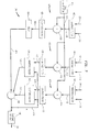
- Figure 7 shows a least mean square LMS-form of adaptive noise cancellation device 244 in detail.
- the noise cancellation could have other forms such as recursive least squares (RLS), but the objective is the same.
- the outputs of the demodulators 431 and 433 are input into two adaptive filters 436 and 442.
- the filters 436 and 442 adaptively filter the first and second noise baseband signals.
- the adaptive filter outputs are subtracted from the input baseband signal 454 by the summer 438.
- the LMS filter weights are adjusted using the error ⁇ and inputs the first and second noise baseband signals 446 and 448 to reduce the minimum-mean-square noise in the output error 444.
- the adaptive filters 436 and 442 must continuously update adaptive weights based on an error signal so that the adaptive filters 436 and 442 may adjust the contributions of first and second noise baseband signals in 454 to minimize the noise induced error signal.
- the error signal is the output of the summer 438 which is fed back to the adaptive filters 436 and 442 through signal line 444.
- the input baseband signal output by the input baseband demodulator 429 must be delayed by a delay unit 434 before input into the summer 438 through signal line 454.
- the delay unit 434 matches in time the signal output by the input baseband demodulator relative to the time of the first and second noise baseband signals output by the adaptive filters 436 and 442.
- the output of the summer 438 is the received input signal which is also the error signal fed back to the adaptive filters 436 and 442.
- the received input signal is input into the baseband receiver 440. If the baseband receiver 440 is a digital receiver, the received input signal is decoded and translated into received data, 1's and 0's, that was transmitted by the original transmitter. The decoded digital signal is output by the adaptive noise cancellation device 244 to other processing functions through signal line 246.
- FIG. 8 shows an exemplary embodiment of the adaptive filter 436 in greater detail. While different adaptive filters may be used, FIG. 8 shows a finite-impulse-response (FIR) least-mean square-error (MMSE) adaptive filter.
- the filter portion 502 receives the first noise baseband signal from signal line 446 and delays the first noise baseband signal by delay units 520, 522 and 524. As indicated by the dotted portion of signal line 536, any number of delay units 520, 522 and 524 may be used depending on a particular design of the least mean square adaptive filter.
- the delay units 520, 522 and 524, multiplier units 506, 508, 510 and 512 and adder units 514, 516 and 518 together form a filter that filters the first noise baseband signal and outputs the filtered first noise baseband signal through signal line 450.
- the filter characteristics are determined by the weights W 1 , W 2 , W 3 ,... W M , where M is the length of the filter. Depending on the particular values of the weights, the frequency characteristic of the filter may be changed.
- the weights W 1 , W 2 ,... W M are adaptive weights.
- the adaptive weights are updated and the updated weights are used by the multipliers 506, 508, 510 and 512 as indicated by the lines connecting a weight update unit 504 and the multipliers 506, 508, 510 and 512.
- the weight update unit 504 calculates new weights based on the current set of weights adjusted by a factor which is a product of a constant g multiplied by the error signal ⁇ (j) multiplied by the first noise baseband signal h(j), where j is the current time.
- the constant g is selected so that the weight update algorithm converges to generate an optimum set of weights W 1 , W 2 ...W M that results in the best removal of the first noise baseband signal from the input baseband signal within the constraint of adaptivity to changing system conditions.
- the error signal ⁇ (j) is the output of the summer 438 which is also the received baseband signal to be detected.
- the first noise baseband signal h(j) is delayed corresponding to the total number of delays applied to the first noise baseband signal by delay units 520, 522 and 524.
- the first noise baseband signal used to update W 1 is an undelayed first noise baseband signal h(j).
- W 2 is updated by using the first noise baseband signal delayed by the delay unit 520, and so on.
- the weight update unit 504 generates weights adaptively to minimize the mean square error component of noise h present in output ⁇ (j) and thus achieves a received input signal having a maximized signal-to-noise ratio at the input of receiver 440.
Landscapes
- Engineering & Computer Science (AREA)
- Power Engineering (AREA)
- Noise Elimination (AREA)
Applications Claiming Priority (2)
| Application Number | Priority Date | Filing Date | Title |
|---|---|---|---|
| US08/871,297 US6313738B1 (en) | 1997-06-09 | 1997-06-09 | Adaptive noise cancellation system |
| US871297 | 1997-06-09 |
Publications (2)
| Publication Number | Publication Date |
|---|---|
| EP0884822A2 true EP0884822A2 (fr) | 1998-12-16 |
| EP0884822A3 EP0884822A3 (fr) | 2000-01-05 |
Family
ID=25357146
Family Applications (1)
| Application Number | Title | Priority Date | Filing Date |
|---|---|---|---|
| EP98304043A Withdrawn EP0884822A3 (fr) | 1997-06-09 | 1998-05-21 | Système de supression adaptative du bruit |
Country Status (2)
| Country | Link |
|---|---|
| US (1) | US6313738B1 (fr) |
| EP (1) | EP0884822A3 (fr) |
Families Citing this family (41)
| Publication number | Priority date | Publication date | Assignee | Title |
|---|---|---|---|---|
| US6452482B1 (en) * | 1999-12-30 | 2002-09-17 | Ambient Corporation | Inductive coupling of a data signal to a power transmission cable |
| GB9827601D0 (en) * | 1998-12-15 | 1999-02-10 | Northern Telecom Ltd | A power line communications system and method of operation thereof |
| US6928046B1 (en) * | 1999-05-05 | 2005-08-09 | Lucent Technologies Inc. | Frame synchronization of an OFDM signal |
| US7154382B2 (en) * | 1999-12-30 | 2006-12-26 | Ambient Corporation | Arrangement of inductive couplers for data communication |
| WO2001054297A1 (fr) * | 2000-01-20 | 2001-07-26 | Current Technologies, Llc | Procede d'isolation de donnees dans un reseau de communications a ligne electrique |
| US6965302B2 (en) | 2000-04-14 | 2005-11-15 | Current Technologies, Llc | Power line communication system and method of using the same |
| BR0110299A (pt) | 2000-04-14 | 2005-08-02 | Current Tech Llc | Comunicações digitais utilizando linhas de distribuição de energia de média voltagem |
| US6998962B2 (en) | 2000-04-14 | 2006-02-14 | Current Technologies, Llc | Power line communication apparatus and method of using the same |
| US7103240B2 (en) | 2001-02-14 | 2006-09-05 | Current Technologies, Llc | Method and apparatus for providing inductive coupling and decoupling of high-frequency, high-bandwidth data signals directly on and off of a high voltage power line |
| KR100569748B1 (ko) * | 2000-10-31 | 2006-04-11 | 티디케이가부시기가이샤 | 전력선 잡음 필터 |
| EP1371219A4 (fr) | 2001-02-14 | 2006-06-21 | Current Tech Llc | Communication de donnees par ligne electrique |
| US7194528B1 (en) * | 2001-05-18 | 2007-03-20 | Current Grid, Llc | Method and apparatus for processing inbound data within a powerline based communication system |
| US7173938B1 (en) | 2001-05-18 | 2007-02-06 | Current Grid, Llc | Method and apparatus for processing outbound data within a powerline based communication system |
| ES2188373B1 (es) * | 2001-05-25 | 2004-10-16 | Diseño De Sistemas En Silencio, S.A. | Procedimiento de optimizacion de la comunicacion para sistema de transmision digital ofdm multiusuario sobre red electrica. |
| US7053756B2 (en) | 2001-12-21 | 2006-05-30 | Current Technologies, Llc | Facilitating communication of data signals on electric power systems |
| JP2003338722A (ja) * | 2002-05-20 | 2003-11-28 | Tdk Corp | ノイズ抑制回路 |
| US7102478B2 (en) | 2002-06-21 | 2006-09-05 | Current Technologies, Llc | Power line coupling device and method of using the same |
| US6982611B2 (en) | 2002-06-24 | 2006-01-03 | Current Technologies, Llc | Power line coupling device and method of using the same |
| US7132819B1 (en) | 2002-11-12 | 2006-11-07 | Current Technologies, Llc | Floating power supply and method of using the same |
| US7076378B1 (en) | 2002-11-13 | 2006-07-11 | Current Technologies, Llc | Device and method for providing power line characteristics and diagnostics |
| US7064654B2 (en) | 2002-12-10 | 2006-06-20 | Current Technologies, Llc | Power line communication system and method of operating the same |
| US6980091B2 (en) | 2002-12-10 | 2005-12-27 | Current Technologies, Llc | Power line communication system and method of operating the same |
| US6965303B2 (en) | 2002-12-10 | 2005-11-15 | Current Technologies, Llc | Power line communication system and method |
| US7075414B2 (en) | 2003-05-13 | 2006-07-11 | Current Technologies, Llc | Device and method for communicating data signals through multiple power line conductors |
| US6980090B2 (en) | 2002-12-10 | 2005-12-27 | Current Technologies, Llc | Device and method for coupling with electrical distribution network infrastructure to provide communications |
| US7046124B2 (en) | 2003-01-21 | 2006-05-16 | Current Technologies, Llc | Power line coupling device and method of using the same |
| JP2004274161A (ja) * | 2003-03-05 | 2004-09-30 | Tdk Corp | ノイズ抑制回路 |
| US6822928B1 (en) * | 2003-04-14 | 2004-11-23 | The United States Of America As Represented By The Secretary Of The Navy | Adaptive sonar signal processing method and system |
| US7079012B2 (en) * | 2004-01-21 | 2006-07-18 | Evans Wetmore | System and method for distributing broadband communication signals over power lines |
| US9001921B1 (en) | 2004-02-18 | 2015-04-07 | Marvell International Ltd. | Circuits, architectures, methods, algorithms, software, and systems for improving the reliability of data communications having time-dependent fluctuations |
| US8938021B1 (en) | 2004-05-06 | 2015-01-20 | Paul Shala Henry | Outbound interference reduction in a broadband powerline system |
| US7804763B2 (en) | 2005-04-04 | 2010-09-28 | Current Technologies, Llc | Power line communication device and method |
| US7671701B2 (en) * | 2006-06-09 | 2010-03-02 | Current Technologies, Llc | Method and device for providing broadband over power line communications |
| US9705562B2 (en) * | 2006-07-25 | 2017-07-11 | Broadcom Europe Limited | Dual transformer communication interface |
| US8472576B2 (en) * | 2008-06-06 | 2013-06-25 | Maxim Integrated Products, Inc. | Jammer canceller for power-line communication |
| US8188855B2 (en) * | 2008-11-06 | 2012-05-29 | Current Technologies International Gmbh | System, device and method for communicating over power lines |
| US8279058B2 (en) | 2008-11-06 | 2012-10-02 | Current Technologies International Gmbh | System, device and method for communicating over power lines |
| US20100111199A1 (en) * | 2008-11-06 | 2010-05-06 | Manu Sharma | Device and Method for Communicating over Power Lines |
| TWI478560B (zh) | 2011-03-06 | 2015-03-21 | Pcn Technology Inc | 資料傳輸與管理的系統及方法 |
| JP2015008354A (ja) * | 2013-06-24 | 2015-01-15 | 富士通株式会社 | 伝送装置および高周波フィルタ |
| US11101105B1 (en) * | 2020-05-28 | 2021-08-24 | Applied Materials Israel Ltd. | Noise reduction of a high voltage supply voltage |
Family Cites Families (4)
| Publication number | Priority date | Publication date | Assignee | Title |
|---|---|---|---|---|
| US4344150A (en) | 1980-07-10 | 1982-08-10 | Newmont Mining Corporation | Coherent noise cancelling filter |
| US5278777A (en) | 1989-10-10 | 1994-01-11 | Nicolet Instrument Corporation | Efficient cancelling of AC line interference in electronic instrumentation |
| US5870016A (en) * | 1997-02-03 | 1999-02-09 | Eva Cogenics Inc Euaday Division | Power line carrier data transmission systems having signal conditioning for the carrier data signal |
| CA2290629A1 (fr) * | 1997-05-21 | 1998-11-26 | Victor M. Depinto | Systeme de detection du bruit d'un ecg |
-
1997
- 1997-06-09 US US08/871,297 patent/US6313738B1/en not_active Expired - Fee Related
-
1998
- 1998-05-21 EP EP98304043A patent/EP0884822A3/fr not_active Withdrawn
Also Published As
| Publication number | Publication date |
|---|---|
| US6313738B1 (en) | 2001-11-06 |
| EP0884822A3 (fr) | 2000-01-05 |
Similar Documents
| Publication | Publication Date | Title |
|---|---|---|
| US6313738B1 (en) | Adaptive noise cancellation system | |
| US6959056B2 (en) | RFI canceller using narrowband and wideband noise estimators | |
| US6940973B1 (en) | Method and apparatus for cancelling common mode noise occurring in communications channels | |
| US5952914A (en) | Power line communication systems | |
| US6993311B2 (en) | Radio receiver having an adaptive equalizer and method therefor | |
| US6052420A (en) | Adaptive multiple sub-band common-mode RFI suppression | |
| US5400084A (en) | Method and apparatus for NTSC signal interference cancellation using recursive digital notch filters | |
| US6047022A (en) | Apparatus and method for transmission of high speed data over communication channels | |
| US5325188A (en) | Apparatus for NTSC signal interference cancellation through the use of digital recursive notch filters | |
| JP3988802B2 (ja) | 無線周波数ノイズ・キャンセラ | |
| EP1245084B1 (fr) | Procede et dispositif d'elimination du bruit de mode commun dans un recepteur dsl | |
| US5282023A (en) | Apparatus for NTSC signal interference cancellation through the use of digital recursive notch filters | |
| US20140098911A1 (en) | Adaptive Frequency-Domain Reference Noise Canceller for Multicarrier Communications Systems | |
| KR20010071126A (ko) | 직접 변환 수신기용 왜곡 정정 회로 | |
| US7738654B2 (en) | Isolation of transmit and receive signals | |
| US7460662B2 (en) | Isolation of transmit and receive signals in full-duplex communication systems | |
| EP0773643A3 (fr) | Réduction d'interférence pour système de télécommunication | |
| WO2001063777A2 (fr) | Eliminateur d'interferences | |
| US4612571A (en) | Constant Z bandswitched input filter | |
| US7123897B2 (en) | Directional receiver coupling arrangement with frequency selectivity and gain control for DSL | |
| US6628969B1 (en) | One-tuner adaptive array | |
| EP2946470A1 (fr) | Méthodes, systèmes et supports lisibles par ordinateur non transitoires pour filtrage à large bande accordable en fréquence et en largeur de bande | |
| US7010277B1 (en) | Arrangement and method for interference cancelling | |
| CN100388633C (zh) | 在二次转频接收器中前馈镜像抑制的设备及方法 | |
| HK1015557A (en) | Adaptive noise cancellation system |
Legal Events
| Date | Code | Title | Description |
|---|---|---|---|
| PUAI | Public reference made under article 153(3) epc to a published international application that has entered the european phase |
Free format text: ORIGINAL CODE: 0009012 |
|
| AK | Designated contracting states |
Kind code of ref document: A2 Designated state(s): DE GB |
|
| AX | Request for extension of the european patent |
Free format text: AL;LT;LV;MK;RO;SI |
|
| PUAL | Search report despatched |
Free format text: ORIGINAL CODE: 0009013 |
|
| AK | Designated contracting states |
Kind code of ref document: A3 Designated state(s): AT BE CH CY DE DK ES FI FR GB GR IE IT LI LU MC NL PT SE |
|
| AX | Request for extension of the european patent |
Free format text: AL;LT;LV;MK;RO;SI |
|
| RIC1 | Information provided on ipc code assigned before grant |
Free format text: 7H 02J 13/00 A, 7H 02J 3/01 B |
|
| 17P | Request for examination filed |
Effective date: 20000204 |
|
| AKX | Designation fees paid |
Free format text: DE GB |
|
| STAA | Information on the status of an ep patent application or granted ep patent |
Free format text: STATUS: THE APPLICATION IS DEEMED TO BE WITHDRAWN |
|
| 18D | Application deemed to be withdrawn |
Effective date: 20021203 |
|
| REG | Reference to a national code |
Ref country code: HK Ref legal event code: WD Ref document number: 1015557 Country of ref document: HK |