EP0884836B1 - Régéneration de signaux en phase et en quadrature - Google Patents
Régéneration de signaux en phase et en quadrature Download PDFInfo
- Publication number
- EP0884836B1 EP0884836B1 EP98110589A EP98110589A EP0884836B1 EP 0884836 B1 EP0884836 B1 EP 0884836B1 EP 98110589 A EP98110589 A EP 98110589A EP 98110589 A EP98110589 A EP 98110589A EP 0884836 B1 EP0884836 B1 EP 0884836B1
- Authority
- EP
- European Patent Office
- Prior art keywords
- signal
- coefficients
- phase
- samples
- phase shifted
- Prior art date
- Legal status (The legal status is an assumption and is not a legal conclusion. Google has not performed a legal analysis and makes no representation as to the accuracy of the status listed.)
- Expired - Lifetime
Links
Images


Classifications
-
- H—ELECTRICITY
- H03—ELECTRONIC CIRCUITRY
- H03D—DEMODULATION OR TRANSFERENCE OF MODULATION FROM ONE CARRIER TO ANOTHER
- H03D3/00—Demodulation of angle-, frequency- or phase- modulated oscillations
- H03D3/007—Demodulation of angle-, frequency- or phase- modulated oscillations by converting the oscillations into two quadrature related signals
- H03D3/008—Compensating DC offsets
-
- G—PHYSICS
- G01—MEASURING; TESTING
- G01S—RADIO DIRECTION-FINDING; RADIO NAVIGATION; DETERMINING DISTANCE OR VELOCITY BY USE OF RADIO WAVES; LOCATING OR PRESENCE-DETECTING BY USE OF THE REFLECTION OR RERADIATION OF RADIO WAVES; ANALOGOUS ARRANGEMENTS USING OTHER WAVES
- G01S7/00—Details of systems according to groups G01S13/00, G01S15/00, G01S17/00
- G01S7/02—Details of systems according to groups G01S13/00, G01S15/00, G01S17/00 of systems according to group G01S13/00
- G01S7/28—Details of pulse systems
- G01S7/285—Receivers
- G01S7/288—Coherent receivers
- G01S7/2886—Coherent receivers using I/Q processing
-
- H—ELECTRICITY
- H04—ELECTRIC COMMUNICATION TECHNIQUE
- H04B—TRANSMISSION
- H04B1/00—Details of transmission systems, not covered by a single one of groups H04B3/00 - H04B13/00; Details of transmission systems not characterised by the medium used for transmission
- H04B1/06—Receivers
- H04B1/16—Circuits
- H04B1/30—Circuits for homodyne or synchrodyne receivers
-
- H—ELECTRICITY
- H04—ELECTRIC COMMUNICATION TECHNIQUE
- H04L—TRANSMISSION OF DIGITAL INFORMATION, e.g. TELEGRAPHIC COMMUNICATION
- H04L27/00—Modulated-carrier systems
-
- H—ELECTRICITY
- H03—ELECTRONIC CIRCUITRY
- H03D—DEMODULATION OR TRANSFERENCE OF MODULATION FROM ONE CARRIER TO ANOTHER
- H03D2200/00—Indexing scheme relating to details of demodulation or transference of modulation from one carrier to another covered by H03D
- H03D2200/0041—Functional aspects of demodulators
- H03D2200/0047—Offset of DC voltage or frequency
Definitions
- the present invention relates to communication signal processing. More specifically, the present invention relates to the regeneration of the in-phase and quadrature signal components received by communication receivers for digitally modulated signals.
- a receiver In many communication, radar or instrumentation applications, a receiver generates two orthogonal signal components of the received signal to ease recovery of information contained within the received signal.
- the two orthogonal baseband signals are generated from an incoming signal having a centre frequency (CF) by mixing the incoming signal with a reference signal tuned to approximately a same CF.
- the in-phase (I) signal results from mixing the incoming signal with the reference signal tuned to approximately a same CF
- the quadrature (Q) signal results from mixing the incoming signal with a version of the reference signal phase shifted by 90°.
- a filter is used to remove undesired products of the mixing.
- Amplification is commonly used to adjust the I and Q signals to suitable levels for further processing.
- phase imbalances between, gain imbalances between and DC offsets on the I and Q signals may affect data derived from these signals resulting in errors in the derived data.
- a method is required to compensate for circuit imbalances between the paths and the DC offsets.
- An approach to I and Q signal regeneration according to the prior art uses a six-port junction based direct receiver (hereafter "6-port receiver”).
- 6-port receiver uses such a receiver and a two-tone calibration technique initially developed for reflectometry applications, an incoming signal is split into three separate signals and a fourth output port provides a signal proportional to the reference signal. These are then used for generation of an I component signal and a Q component signal.
- the function of such a receiver requires that an incoming signal is split into three versions each phase shifted from the other two versions by 120 degrees. This technique has specific requirements on the incoming signal to perform its calibration and is computationally intensive for real time applications.
- the primary object of the invention is to provide a method for regenerating I&Q signals from an incoming signal in the presence of gain imbalances, phase imbalances and DC offsets in regeneration circuitry.
- the method is applicable to signals either at baseband or at another centre frequency.
- Another object of the present invention is to compensate in the receiver for signal distortion due to gain and phase imbalances in the generation circuit at a transmitter.
- an in-phase and quadrature signal regeneration circuit for use with one of a quadrature receiver and a quadrature transmitter, as defined by claim 13.
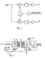
- a common approach to generating two orthogonal baseband signals from an incoming signal having a centre frequency (CF) comprises mixing the incoming signal with a reference signal tuned to approximately a same CF, as shown in Fig. 1 .
- the in-phase (I) signal results from mixing the incoming signal with the reference signal tuned to approximately a same CF and the quadrature (Q) signal results from mixing the incoming signal with a version of the reference signal phase shifted by 90°.
- a filter is used to remove undesired products of the mixing.
- Amplification is commonly used to adjust the I and Q signals to suitable levels for further processing.
- RF modulated input signal of interest (RF signal) is fed to a port 1 of a six-port junction.
- a reference signal (LO signal), at a frequency close to a centre frequency of the RF signal, is fed to another port 2 of the receiver from a signal generator 10.
- Signals provided at each of three of the output ports 3, 4, 5 are vector sums of the two input signals with a total phase difference between each of them of 120°.
- a signal provided at a fourth output port 6 is proportional to the LO signal.
- These four output signals are fed to square-law diodes 11, power detectors, to produce baseband signals and are then filtered and amplified with filters and amplifiers 12 and sampled to form digital signals using analog to digital converters 13. Optionally, separate filters and amplifiers are used. The filtering is required to prevent anti-aliasing .
- the four digital signals are fed to an I&Q signal regeneration processing unit 15.
- the regeneration function entails determination of regeneration coefficients from a set of samples and application of these coefficients to incoming samples to produce two baseband signals in quadrature - in-phase and quadrature signals. Then, normal demodulation circuitry is applied.
- Fig. 3 shows a functional block diagram of a six-port junction. Many topologies may be used to implement this functionality.
- a phase difference between a vector sum of the RF and LO signals at ports 3,4 and 5 is nominally 120°.
- Design constraints include a need for a 120° phase difference, ideally, between the three output ports; minimum attenuation of the RF and LO signal components; and good isolation between the reference output port (Port 6) and the RF signal input port. These constraints are difficult to meet. Commonly, fabrication imperfections introduce errors and the constraints are, thereby, not met. Because the main use of 6-port junction devices is in reflectometer applications as a basic instrument to measure impedance, there is a need to calibrate such a 6-port junction. Several calibration techniques are known.
- the present invention addresses the compensation of phase imbalances, gain imbalance and DC offsets in I&Q regeneration circuits.
- the method and circuit for carrying out the method allow for relaxed specifications for front-end electronic circuitry.
- One use of the present invention is in a multi-port junction based direct receiver for communication applications having 4 or more ports.
- a basic element to regenerate in-phase and quadrature signal components of an incoming signal First, the incoming signal is split into three paths ⁇ 0 . ⁇ 1, and ⁇ 2 , each path resulting in a different phase shift of the incoming signal r(t). The amount of phase shift between each phase-shifted signal must be different than 0° and 180° and, optimally, is approximately 120° for the three signal paths.
- the phase-shifted signals are digitised using an analog to digital converter 31 and samples of each are provided to a processor 32. The samples are used to determine regeneration coefficients.
- these coefficients are passed to a regeneration circuit 33 where the coefficients are applied to samples of the phase shifted versions of the signal r(t) in order to extract I&Q signal components therefrom.
- the regeneration coefficients are updated regularly to compensate for changes due to time or temperature induced variations. In some cases, updating of the regeneration coefficients is unnecessary; when unnecessary, determining the regeneration coefficients is performed once during the initial setup of the receiver.
- the processor 32 determines the regeneration coefficients using an eigen-decomposition method.
- the processor 32 operates on M sets of signal samples in performing the determination of the regeneration coefficients. There are constraints on correlation between samples. For example, for a signal corrupted by additive white Gaussian noise (AWGN), the sets of samples are sometimes contiguous in time; however, when the process corrupting the samples has memory, the samples should preferably be more spaced in time. The number M of sets of samples is not extremely large.
- AWGN additive white Gaussian noise
- Eigenvalues are ranked such that: ⁇ 1 * ⁇ ⁇ 2 * ⁇ ⁇ 3 *
- coefficients are updated on a continuous basis or established once during initial setup of the receiver. In the latter case, initial gain, phase, and DC offset characteristics of the front end receiver circuit are maintained. Any fluctuations in gain imbalances, phase imbalances and DC offsets occurring after the coefficient calculations are reflected in the regenerated I and Q signal samples and, where generated, in the regenerated I and Q signals because of a linear relationship between the three input signals and the I and Q output signals.
- a smooth transition occurs from one set of coefficients to a next set of coefficients in order to prevent large phase, gain and DC offset discontinuities in resulting I and Q signals.
- a simple linear interpolation between a current set of coefficients and a new set of coefficients performed over a few tens of sample periods is often acceptable.
- a least-mean square adaptive algorithm is used to indirectly perform eigen decomposition and to derive two projection vectors that project a vector of samples of multiple phase shifted signal versions onto a two-dimensional signal subspace comprising a subspace for an in-phase signal component and a subspace for a quadrature signal component.
- This procedure updates the coefficients continuously.
- the procedure has an inherent coherency since the coefficients are derived from the previous values by adding a small correction attributed to the new measurements. This inherent coherency eliminates phase, gain and DC offset discontinuities.
- a signal generator 50 provides a reference signal at a centre frequency of an incoming signal r(t) to a port 2 of the receiver.
- the incoming signal r(t) is provided to a port 1 of the receiver.
- Three signals are provided one at each of three output ports 3, 4, and 5.
- the signals are shifted in phase relative to each other. Of course, this requires shifting at least two of the signals in phase. Since samples of the phase shifted signals are desired, shifting of phase for the sampled signals may occur before, during, or after sampling.
- I and Q signal sample regeneration comprises a step of combining the samples resulting from the analog to digital conversion in a linear fashion in order to determine quantised samples of the I and Q signal components for use by the demodulator 57 to determine output data bits.
- the linear combination coefficients are determined by the processor 34 based on sets of digital signal samples gathered at least once, and potentially periodically. Eight coefficients are determined for use in the I and Q signal regeneration circuit. According to the invention, coefficients are determined for compensating for phase imbalances, gain imbalances and DC offsets in the three output signals provided from the five-port junction based direct receiver.
- In-phase and quadrature signal components of an incoming signal are determined by a linear combination of three phase shifted versions of the received signal.
- N 3 in the equations above.
- Linear combination coefficients a i and b i , are calculated from samples of the incoming signal.
- the M sets of samples are used to calculate a correlation matrix R D either recursively or directly.
- the eigenvectors associated with the two smallest eigenvalues are then computed, normalised and scaled.
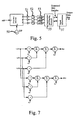
- Fig. 6 shows a simplified flow diagram of calculation steps for calculating the regeneration coefficients. Often, it is sufficient to perform the calculations with twice as much accuracy as that of the sampling analog to digital converter; for example, when using 8 bit samples, it is preferable to use 16-bit accuracy in calculations.
- sample size is specified, memory is initialised, and parameters are set, when necessary. This initialises the system for coefficient generation.
- samples are gathered from each of the phase shifted signals.
- shifting of phase for the sampled signals is performed in any of numerous fashions.
- the signal is split into three identical copies, which are phase shifted differently and then sampled.
- sampling is performed on a single signal at intervals, which result in three or more sampled signals each having a phase offset from the other sampled signals.
- the samples are then used to update the correlation matrix and the mean of each of the three or more signals.
- the number of samples is M, the number for generation of new coefficients, then the eigenvalues are determined and an eigenvector is formed as described above. DC offsets a 0 and b 0 are computed and the sample counter is reset. Then the I and Q signal sample regeneration is performed according to the above noted equations. When the number of samples is less than M, the I and Q signal sample regeneration is performed according to the above noted equations and the sample counter is incremented.
- Fig. 7 shows a functional block diagram of I and Q signal sample regeneration once the coefficients are known.
- the processing is easily implemented using digital hardware. Alternatively, an analog processor is used.
- phase shifted versions of the received signal are provided, for example, by a five-port junction.
- receivers with more than 5 ports function correctly, analysis shows little or no improvement in the resulting in-phase and quadrature signals using a receiver with more than 5 ports over receivers having 5 ports.
- acceptable performance is obtained with two phase shifted versions of the received signal as are obtained, for example, using a four-port junction.
- the frequency conversion is made using detector diodes as in the junction based receiver shown, amplitude modulation present on a desired signal and on any adjacent signals is folded into the desired signal band.
- the regeneration method requires only two baseband phase shifted versions of the received signal without loss of performance. Therefore a receiver with 4 ports functions adequately for some applications.
- phase shifted versions of the received signal is required when the received or any adjacent signals have amplitude modulation, and this modulation is not desired - the signals are brought to baseband using a direct receiver approach.
- the new method based on three phase shifted versions of the received signal allows the removal of the amplitude modulation noise introduced within the signal band.
- use of two phase shifted versions of the received signal according to the invention is useful.
- Using a 4-port junction based direct receiver hardware and processing are simplified as illustrated in Fig. 8 .
- the method is applicable using a four-port junction based direct receiver.
- amplitude modulation noise exists, an implementation using three or more phase shifted versions of the received signal is preferred.
Landscapes
- Engineering & Computer Science (AREA)
- Computer Networks & Wireless Communication (AREA)
- Signal Processing (AREA)
- Physics & Mathematics (AREA)
- General Physics & Mathematics (AREA)
- Radar, Positioning & Navigation (AREA)
- Remote Sensing (AREA)
- Power Engineering (AREA)
- Digital Transmission Methods That Use Modulated Carrier Waves (AREA)
- Radar Systems Or Details Thereof (AREA)
Claims (17)
- Un procédé de régénération de signal en phase et de régénération de signal en quadrature, le procédé compensant des déséquilibres de phase, des déséquilibres de gain ou des décalages c. c. ou une combinaison de ceux-ci, le procédé comprenant les opérations suivantes :la réception d'un signal,la génération d'une pluralité de versions déphasées numérisées du signal reçu, les versions étant déphasées les unes des autres d'une quantité autre que 0 et 180 degrés,la génération d'une matrice de corrélation, la matrice de corrélation étant dépendante de la pluralité de versions déphasées numérisées,la détermination de valeurs propres à partir d'une décomposition de la matrice de corrélation,le classement des valeurs propres déterminées et la sélection de deux des valeurs propres,la détermination de composants de vecteur propre associés aux deux valeurs propres sélectionnées,la mise en correspondance des composants de vecteur propre avec des coefficients de régénération,la détermination de coefficients de compensation de décalage c. c.,la fourniture des coefficients sous la forme de coefficients de combinaison linéaire, etl'application des coefficients de combinaison linéaire aux versions déphasées numérisées du signal de façon à extraire des composants en phase et en quadrature du signal reçu de celles-ci.
- Le procédé selon la Revendication 1 caractérisé en ce que la matrice de corrélation est déterminée de manière récursive à partir d'un nombre prédéterminé d'ensembles d'échantillons de signal de chacune des versions de la pluralité de versions déphasées numérisées.
- Le procédé selon l'une quelconque des Revendications 1 et 2, caractérisé en ce que la pluralité de versions sont des versions de bande de base du signal reçu, les versions étant sensiblement similaires aux versions de bande de base numérisées obtenues par un échantillonnage d'une pluralité de signaux de bande de base identiques déphasés les uns des autres d'une quantité autre que 0 et 180 degrés.
- Le procédé selon l'une quelconque des Revendications 1 et 2, caractérisé en ce que les coefficients de compensation de décalage c. c. sont déterminés au moyen des coefficients de régénération.
- Le procédé selon l'une quelconque des Revendications 1 et 2, caractérisé en ce que les coefficients de compensation de décalage c. c. sont déterminées au moyen d'une valeur moyenne de chaque signal.
- Le procédé selon la Revendication 4 caractérisé en ce que les deux plus petites valeurs propres sont sélectionnées lorsqu'un composant c. c. est présent dans le signal reçu.
- Le procédé selon la Revendication 4 caractérisé en ce que les deux plus grandes valeurs propres sont sélectionnées lorsqu'un composant c. c. n'est pas présent dans le signal reçu.
- Le procédé selon l'une quelconque des Revendications 4 à 7 caractérisé en ce que l'opération d'application des coefficients de régénération comprend les opérations suivantes :la réception des coefficients de régénération,la multiplication d'échantillons provenant des versions déphasées numérisées avec des coefficients de régénération associés afin de produire des résultats et l'addition des résultats de façon à produire une estimation d'échantillons des composants de signaux en phase et en quadrature, etl'addition des coefficients de compensation c. c. avec l'estimation d'échantillons des composants de signaux en phase et en quadrature de façon à produire des échantillons des composants de signaux en phase et en quadrature.
- Le procédé selon la Revendication 1 caractérisé en ce que les trois versions déphasées numérisées du signal reçu sont générées et comprenant l'opération de :projection de données dérivées de chacune des trois versions déphasées numérisées vers un sous-espace de signal possédant au moins deux dimensions.
- Le procédé selon la Revendication 9, comprenant les opérations suivantes :la détermination à partir des échantillons d'une valeur moyenne pour chaque signal, les valeurs moyennes étant destinées à compenser des décalages c. c., etla détermination à partir des échantillons d'une pluralité de coefficients destinés à une utilisation dans la mise en correspondance des trois versions déphasées numérisées du signal reçu dans au moins deux dimensions,et caractérisé en ce que des échantillons provenant de chaque version déphasée numérisée sont multipliés par un coefficient déterminé et combinés de manière linéaire.
- Le procédé selon l'une quelconque des Revendications 9 et 10 caractérisé en ce que les données dérivées de chacun des trois signaux sont assemblées en un vecteur comprenant un échantillon provenant de chaque version déphasée numérisée et où l'opération de projection comprend l'opération de transformation du vecteur.
- Le procédé selon la Revendication 11 comprenant l'opération de génération d'un signal en quadrature et en phase à partir des données de vecteur transformées au moyen d'un convertisseur numérique à analogique.
- Un circuit de régénération de signal en quadrature et en phase destiné à une utilisation avec un récepteur en quadrature, le circuit compensant des déséquilibres de phase, des déséquilibres de gain ou des décalages c. c. ou une combinaison de ceux-ci, le circuit comprenant :un convertisseur analogique à numérique (31) destiné à générer une pluralité de versions déphasées numérisées d'un signal reçu par le récepteur en quadrature, etun processeur (33) destiné à l'exécution de :la génération d'une matrice de corrélation, la matrice de corrélation étant dépendante de la pluralité de versions déphasées numérisées,la détermination de valeurs propres à partir d'une décomposition de la matrice de corrélation,le classement des valeurs propres déterminées et la sélection de deux des valeurs propres,la détermination de composants de vecteur propre associés aux deux valeurs propres sélectionnées,la mise en correspondance des composants de vecteur propre avec des coefficients de régénération,la détermination de coefficients de compensation de décalage c. c.,la fourniture des coefficients sous la forme de coefficients de combinaison linéaire, etl'application des coefficients de combinaison linéaire aux versions déphasées numérisées du signal de façon à extraire des composants en phase et en quadrature du signal reçu de celles-ci.
- Un circuit selon la Revendication 13 comprenant une jonction à cinq ports destinée à la réception d'un signal reçu par le récepteur en quadrature, à la réception d'un signal de référence et à la fourniture de trois signaux de bande de base relatifs aux signaux reçus, chaque signal de bande de base étant déphasé par rapport aux autres.
- Un circuit selon l'une quelconque des Revendications 13 et 14, caractérisé en ce que le processeur comprend un moyen d'exécuter les opérations suivantes :la détermination d'une matrice de corrélation des versions déphasées numérisées par rapport à un ensemble d'échantillons d'une taille prédéterminée, etla détermination d'une valeur moyenne de chaque version déphasée numérisée par rapport à l'ensemble d'échantillons.
- Un circuit selon la Revendication 13, caractérisé en ce que le processeur comprend un moyen de déterminer des coefficients de compensation de décalage c. c. au moyen des coefficients de régénération.
- Un circuit selon la Revendication 13, caractérisé en ce que le processeur comprend un moyen de déterminer des coefficients de compensation de décalage c. c. au moyen d'une valeur moyenne de chaque signal.
Applications Claiming Priority (2)
| Application Number | Priority Date | Filing Date | Title |
|---|---|---|---|
| US4904997P | 1997-06-10 | 1997-06-10 | |
| US49049P | 1997-06-10 |
Publications (2)
| Publication Number | Publication Date |
|---|---|
| EP0884836A1 EP0884836A1 (fr) | 1998-12-16 |
| EP0884836B1 true EP0884836B1 (fr) | 2009-11-25 |
Family
ID=21957798
Family Applications (1)
| Application Number | Title | Priority Date | Filing Date |
|---|---|---|---|
| EP98110589A Expired - Lifetime EP0884836B1 (fr) | 1997-06-10 | 1998-06-09 | Régéneration de signaux en phase et en quadrature |
Country Status (4)
| Country | Link |
|---|---|
| US (1) | US6337888B1 (fr) |
| EP (1) | EP0884836B1 (fr) |
| CA (1) | CA2239681C (fr) |
| DE (1) | DE69841295D1 (fr) |
Families Citing this family (42)
| Publication number | Priority date | Publication date | Assignee | Title |
|---|---|---|---|---|
| AU2274899A (en) * | 1997-12-18 | 1999-07-12 | Sony International (Europe) Gmbh | N-port direct receiver |
| EP1011204B1 (fr) | 1998-12-18 | 2005-04-13 | Sony International (Europe) GmbH | Récepteur utilisant un circuit à trois portes |
| EP1056193B1 (fr) * | 1999-05-27 | 2005-04-27 | Sony International (Europe) GmbH | Convertisseur vers le bas et démodulateur utilisant une jonction à trois portes |
| DE69932705T2 (de) * | 1999-06-16 | 2007-08-16 | Sony Deutschland Gmbh | Empfänger mit N Toren |
| DE69924989T2 (de) * | 1999-07-08 | 2006-02-23 | Sony International (Europe) Gmbh | Kalibrierung eines Empfängers mit N -Toren |
| DE60038369T2 (de) * | 2000-06-28 | 2009-03-05 | Sony Deutschland Gmbh | Vorrichtung zur modulationserkennung |
| US6823181B1 (en) * | 2000-07-07 | 2004-11-23 | Sony Corporation | Universal platform for software defined radio |
| EP1172927B1 (fr) * | 2000-07-11 | 2006-04-12 | Sony Deutschland GmbH | Démodulateur en quadrature utilisant capteurs de puissance |
| EP1189338A1 (fr) | 2000-09-06 | 2002-03-20 | Sony International (Europe) GmbH | Démodulateur I/Q à trois détecteurs de puissance et deux convertisseurs A/N |
| JPWO2002031965A1 (ja) * | 2000-10-12 | 2004-02-26 | ソニー株式会社 | 復調器およびそれを用いた受信機 |
| US6711219B2 (en) * | 2000-12-04 | 2004-03-23 | Tensorcomm, Incorporated | Interference cancellation in a signal |
| US6977977B1 (en) * | 2001-02-20 | 2005-12-20 | Comsys Communication & Signal Processing Ltd. | Compensation of I/Q gain mismatch in a communications receiver |
| EP1450481A4 (fr) * | 2001-11-30 | 2005-02-09 | Sony Corp | Demodulateur et recepteur le mettant en application |
| US6734820B2 (en) | 2002-05-13 | 2004-05-11 | Honeywell International Inc. | Methods and apparatus for conversion of radar return data |
| US6768469B2 (en) | 2002-05-13 | 2004-07-27 | Honeywell International Inc. | Methods and apparatus for radar signal reception |
| US6639545B1 (en) | 2002-05-13 | 2003-10-28 | Honeywell International Inc. | Methods and apparatus to determine a target location in body coordinates |
| US6950056B2 (en) * | 2002-05-13 | 2005-09-27 | Honeywell International Inc. | Methods and apparatus for determination of a filter center frequency |
| US6803878B2 (en) | 2002-05-13 | 2004-10-12 | Honeywell International Inc. | Methods and apparatus for terrain correlation |
| US6856279B2 (en) * | 2002-05-13 | 2005-02-15 | Honeywell International Inc. | Methods and apparatus for determining an interferometric angle to a target in body coordinates |
| US6744401B2 (en) | 2002-05-13 | 2004-06-01 | Honeywell International Inc. | Methods and apparatus for radar data processing |
| US6674397B2 (en) | 2002-05-13 | 2004-01-06 | Honeywell International Inc. | Methods and apparatus for minimum computation phase demodulation |
| US6680691B2 (en) | 2002-05-13 | 2004-01-20 | Honeywell International Inc. | Methods and apparatus for accurate phase detection |
| DE60215923T2 (de) * | 2002-06-20 | 2007-05-10 | Sony Deutschland Gmbh | I/Q Demodulator unter Verwendung einer Sechs-Tor-Schaltung |
| DE60224929T2 (de) * | 2002-09-16 | 2009-01-29 | Sony Deutschland Gmbh | Adaptives Selbstkalibrierungsverfahren für einen Quadraturdemodulator eines Fünfport-Empfängers |
| KR100457924B1 (ko) * | 2002-10-07 | 2004-11-18 | 한국전자통신연구원 | I 채널 및 q 채널 간 이득 및 위상 불일치를 보상하는직교 복조 장치 |
| US7369813B2 (en) * | 2003-05-14 | 2008-05-06 | Telefonaktiebolaget L M Ericsson (Publ) | Fast calibration of electronic components |
| US7310504B2 (en) * | 2004-03-26 | 2007-12-18 | Agilent Technologies, Inc. | IF frequency response characterization employing overlapping frequency bands |
| US7463866B1 (en) | 2005-04-13 | 2008-12-09 | Rf Micro Devices, Inc. | I/Q mismatch calibration of direct conversion transceivers using the OFDM short training sequence |
| US7395202B2 (en) * | 2005-06-09 | 2008-07-01 | Motorola, Inc. | Method and apparatus to facilitate vocoder erasure processing |
| KR100843421B1 (ko) * | 2007-02-27 | 2008-07-03 | 삼성전기주식회사 | 5-포트 네트워크의 i/q 재생 장치 |
| US7848450B2 (en) * | 2007-03-22 | 2010-12-07 | Texas Instruments Incorporated | Methods and apparatus to pre-compensate for I/Q distortion in quadrature transmitters |
| KR100946124B1 (ko) * | 2008-12-08 | 2010-03-10 | 삼성전기주식회사 | 멀티포트 네트워크의 i/q 신호 재생 장치 및 그 방법 |
| US8750441B2 (en) * | 2010-12-20 | 2014-06-10 | Texas Instruments Incorporated | Signal cancellation to reduce phase noise, period jitter, and other contamination in local oscillator, frequency timing, or other timing generators or signal sources |
| US9264268B2 (en) | 2012-10-12 | 2016-02-16 | Innoventure L.P. | Periodic time segment sequence based decimation |
| US9484969B2 (en) | 2012-10-12 | 2016-11-01 | Innoventure L.P. | Delta-pi signal acquisition |
| US9490944B2 (en) | 2012-10-12 | 2016-11-08 | Innoventure L.P. | Phase sector based RF signal acquisition |
| US9225368B2 (en) | 2012-10-12 | 2015-12-29 | Innoventure L.P. | Periodic time segment sequence based signal generation |
| US9484968B2 (en) | 2012-10-12 | 2016-11-01 | Innoventure L.P. | Post conversion mixing |
| WO2014172294A1 (fr) * | 2013-04-15 | 2014-10-23 | Aoptix Technologies, Inc. | Récupération de fréquence et de phase de porteuse dans les communications dans la bande e codées en quadrature |
| US11054499B2 (en) * | 2016-01-22 | 2021-07-06 | Texas Instruments Incorporated | Digital compensation for mismatches in a radar system |
| CN114236471B (zh) * | 2021-12-18 | 2025-05-06 | 中国科学技术大学 | 一种相关干扰源下的稳健自适应波束形成方法 |
| CN115800287B (zh) * | 2022-10-27 | 2023-10-27 | 深圳市国电科技通信有限公司 | 一种基于阈值分割聚类的低压台区拓扑识别方法 |
Family Cites Families (6)
| Publication number | Priority date | Publication date | Assignee | Title |
|---|---|---|---|---|
| US5095536A (en) | 1990-03-23 | 1992-03-10 | Rockwell International Corporation | Direct conversion receiver with tri-phase architecture |
| US5263196A (en) | 1990-11-19 | 1993-11-16 | Motorola, Inc. | Method and apparatus for compensation of imbalance in zero-if downconverters |
| US5461646A (en) * | 1993-12-29 | 1995-10-24 | Tcsi Corporation | Synchronization apparatus for a diversity receiver |
| JP2850942B2 (ja) | 1994-07-13 | 1999-01-27 | 日本電気株式会社 | 復調器 |
| US5822368A (en) * | 1996-04-04 | 1998-10-13 | Lucent Technologies Inc. | Developing a channel impulse response by using distortion |
| FI102702B (fi) | 1996-05-03 | 1999-01-29 | Nokia Mobile Phones Ltd | Menetelmä suoramuunnosvastaanottimen toteuttamiseksi 6-porttipiirillä |
-
1998
- 1998-06-05 CA CA002239681A patent/CA2239681C/fr not_active Expired - Fee Related
- 1998-06-08 US US09/092,945 patent/US6337888B1/en not_active Expired - Lifetime
- 1998-06-09 EP EP98110589A patent/EP0884836B1/fr not_active Expired - Lifetime
- 1998-06-09 DE DE69841295T patent/DE69841295D1/de not_active Expired - Lifetime
Also Published As
| Publication number | Publication date |
|---|---|
| DE69841295D1 (de) | 2010-01-07 |
| CA2239681A1 (fr) | 1998-12-10 |
| EP0884836A1 (fr) | 1998-12-16 |
| US6337888B1 (en) | 2002-01-08 |
| CA2239681C (fr) | 2007-08-21 |
Similar Documents
| Publication | Publication Date | Title |
|---|---|---|
| EP0884836B1 (fr) | Régéneration de signaux en phase et en quadrature | |
| US7088765B1 (en) | Vector calibration system | |
| EP2060081B1 (fr) | Estimation d'un déséquilibre I/Q dépendant de la fréquence | |
| RU2407025C2 (ru) | Ослабление фазовой многолучевости | |
| US6842489B2 (en) | Coherent adaptive calibration system and method | |
| US4621365A (en) | Synchronization preamble correlation detector and frequency estimator | |
| US8976914B2 (en) | Multi-tap IQ imbalance estimation and correction circuit and method | |
| JP5226186B2 (ja) | 入力信号と基準周波数との周波数差を得る方法並びにこの方法を実行する弁別装置、gps受信機及びコンピュータプログラム | |
| EP0496621B1 (fr) | Système pour contrÔler les défauts de la phase et de l'amplification d'un récepteur I/Q avec transposition directe | |
| US4584710A (en) | Coherent receiver phase and amplitude alignment circuit | |
| JP3050383B2 (ja) | 信号の周波数及び位相のデジタル式評価法及び該方法を実施するための装置 | |
| KR100581059B1 (ko) | 직교 복조 수신 시스템에서 가변루프이득을 이용한 동위상채널과 직교 채널 간 위상 및 이득 불일치 보상 장치 및그 방법 | |
| US9985812B1 (en) | Systems and methods for IQ demodulation with error correction | |
| EP2894823A1 (fr) | Estimation du coefficient d'étalonnage du QI numérique | |
| US5339040A (en) | AM demodulation receiver using digital signal processor | |
| Green et al. | Quadrature receiver mismatch calibration | |
| US20040125893A1 (en) | Methods and systems for tracking of amplitudes, phases and frequencies of a multi-component sinusoidal signal | |
| EP0568056B1 (fr) | Dispositif pour la correction d'erreurs de phase de quadrature d'un démodulateur synchrone | |
| US20040022547A1 (en) | Kalman filter intensity noise subtraction for optical heterodyne receivers | |
| CN117713960A (zh) | 一种宽带零中频接收阵列的通道标校与均衡方法 | |
| EP1067675B1 (fr) | Calibration d'un récepteur à N portes | |
| EP0271266B1 (fr) | Traitement de signal | |
| CA2356476C (fr) | Methode pour calibrer un systeme de radiogoniometrie a large bande | |
| US11881620B2 (en) | Method for decoupling signals in transceiver systems | |
| KR100758302B1 (ko) | 직교 복조 수신시스템에서의 반송파 위상 복원 및i/q채널간 위상불일치 보상 장치 및 그 방법 |
Legal Events
| Date | Code | Title | Description |
|---|---|---|---|
| PUAI | Public reference made under article 153(3) epc to a published international application that has entered the european phase |
Free format text: ORIGINAL CODE: 0009012 |
|
| AK | Designated contracting states |
Kind code of ref document: A1 Designated state(s): DE FR GB IT |
|
| AX | Request for extension of the european patent |
Free format text: AL;LT;LV;MK;RO;SI |
|
| RIN1 | Information on inventor provided before grant (corrected) |
Inventor name: DE LESELEUC, MICHEL Inventor name: HINDSON, DANIEL J. Inventor name: CARON, MARIO Inventor name: HUANG, XINPING |
|
| 17P | Request for examination filed |
Effective date: 19990610 |
|
| AKX | Designation fees paid |
Free format text: DE FR GB IT |
|
| 17Q | First examination report despatched |
Effective date: 20021127 |
|
| 17Q | First examination report despatched |
Effective date: 20021127 |
|
| RAP1 | Party data changed (applicant data changed or rights of an application transferred) |
Owner name: HER MAJESTY THE QUEEN IN RIGHT OF CANADA, AS REPRE |
|
| RAP1 | Party data changed (applicant data changed or rights of an application transferred) |
Owner name: E.B. WELLS ELECTRONICS II, L.L.C. |
|
| GRAP | Despatch of communication of intention to grant a patent |
Free format text: ORIGINAL CODE: EPIDOSNIGR1 |
|
| RTI1 | Title (correction) |
Free format text: IN-PHASE AND QUADRATURE SIGNAL REGENERATION |
|
| GRAS | Grant fee paid |
Free format text: ORIGINAL CODE: EPIDOSNIGR3 |
|
| GRAA | (expected) grant |
Free format text: ORIGINAL CODE: 0009210 |
|
| AK | Designated contracting states |
Kind code of ref document: B1 Designated state(s): DE FR GB IT |
|
| REG | Reference to a national code |
Ref country code: GB Ref legal event code: FG4D |
|
| REF | Corresponds to: |
Ref document number: 69841295 Country of ref document: DE Date of ref document: 20100107 Kind code of ref document: P |
|
| PLBE | No opposition filed within time limit |
Free format text: ORIGINAL CODE: 0009261 |
|
| STAA | Information on the status of an ep patent application or granted ep patent |
Free format text: STATUS: NO OPPOSITION FILED WITHIN TIME LIMIT |
|
| 26N | No opposition filed |
Effective date: 20100826 |
|
| PG25 | Lapsed in a contracting state [announced via postgrant information from national office to epo] |
Ref country code: IT Free format text: LAPSE BECAUSE OF FAILURE TO SUBMIT A TRANSLATION OF THE DESCRIPTION OR TO PAY THE FEE WITHIN THE PRESCRIBED TIME-LIMIT Effective date: 20091125 |
|
| REG | Reference to a national code |
Ref country code: DE Ref legal event code: R082 Ref document number: 69841295 Country of ref document: DE Representative=s name: DR. RALF KOTITSCHKE, DE Ref country code: DE Ref legal event code: R082 Ref document number: 69841295 Country of ref document: DE Representative=s name: KOTITSCHKE & HEURUNG PARTNERSCHAFT MBB, DE Ref country code: DE Ref legal event code: R082 Ref document number: 69841295 Country of ref document: DE Representative=s name: KOTITSCHKE & HEURUNG PARTNERSCHAFT MBB PATENT-, DE |
|
| REG | Reference to a national code |
Ref country code: FR Ref legal event code: PLFP Year of fee payment: 18 |
|
| REG | Reference to a national code |
Ref country code: FR Ref legal event code: PLFP Year of fee payment: 19 |
|
| REG | Reference to a national code |
Ref country code: FR Ref legal event code: PLFP Year of fee payment: 20 |
|
| PGFP | Annual fee paid to national office [announced via postgrant information from national office to epo] |
Ref country code: GB Payment date: 20170526 Year of fee payment: 20 Ref country code: FR Payment date: 20170518 Year of fee payment: 20 |
|
| PGFP | Annual fee paid to national office [announced via postgrant information from national office to epo] |
Ref country code: DE Payment date: 20170623 Year of fee payment: 20 |
|
| REG | Reference to a national code |
Ref country code: DE Ref legal event code: R071 Ref document number: 69841295 Country of ref document: DE |
|
| REG | Reference to a national code |
Ref country code: GB Ref legal event code: PE20 Expiry date: 20180608 |
|
| PG25 | Lapsed in a contracting state [announced via postgrant information from national office to epo] |
Ref country code: GB Free format text: LAPSE BECAUSE OF EXPIRATION OF PROTECTION Effective date: 20180608 |