EP0884862A1 - Dispositif de radiocommunication d'un systeme de transmission en diversite - Google Patents
Dispositif de radiocommunication d'un systeme de transmission en diversite Download PDFInfo
- Publication number
- EP0884862A1 EP0884862A1 EP97946820A EP97946820A EP0884862A1 EP 0884862 A1 EP0884862 A1 EP 0884862A1 EP 97946820 A EP97946820 A EP 97946820A EP 97946820 A EP97946820 A EP 97946820A EP 0884862 A1 EP0884862 A1 EP 0884862A1
- Authority
- EP
- European Patent Office
- Prior art keywords
- transmitters
- channels
- signal
- reception
- transmission
- Prior art date
- Legal status (The legal status is an assumption and is not a legal conclusion. Google has not performed a legal analysis and makes no representation as to the accuracy of the status listed.)
- Withdrawn
Links
- 230000005540 biological transmission Effects 0.000 title claims abstract description 121
- 238000004891 communication Methods 0.000 claims abstract description 50
- 238000009792 diffusion process Methods 0.000 claims description 11
- 230000005684 electric field Effects 0.000 claims description 6
- 230000015572 biosynthetic process Effects 0.000 description 25
- 238000003786 synthesis reaction Methods 0.000 description 25
- 238000000034 method Methods 0.000 description 16
- 230000003247 decreasing effect Effects 0.000 description 4
- 238000001514 detection method Methods 0.000 description 4
- 238000010295 mobile communication Methods 0.000 description 4
- 238000006243 chemical reaction Methods 0.000 description 2
- 230000015556 catabolic process Effects 0.000 description 1
- 238000006731 degradation reaction Methods 0.000 description 1
- 238000010586 diagram Methods 0.000 description 1
- 230000000694 effects Effects 0.000 description 1
- 230000005672 electromagnetic field Effects 0.000 description 1
- 238000001914 filtration Methods 0.000 description 1
- 238000012986 modification Methods 0.000 description 1
- 230000004048 modification Effects 0.000 description 1
- 230000008054 signal transmission Effects 0.000 description 1
Images


Classifications
-
- H—ELECTRICITY
- H04—ELECTRIC COMMUNICATION TECHNIQUE
- H04B—TRANSMISSION
- H04B7/00—Radio transmission systems, i.e. using radiation field
- H04B7/02—Diversity systems; Multi-antenna system, i.e. transmission or reception using multiple antennas
- H04B7/04—Diversity systems; Multi-antenna system, i.e. transmission or reception using multiple antennas using two or more spaced independent antennas
- H04B7/06—Diversity systems; Multi-antenna system, i.e. transmission or reception using multiple antennas using two or more spaced independent antennas at the transmitting station
- H04B7/0602—Diversity systems; Multi-antenna system, i.e. transmission or reception using multiple antennas using two or more spaced independent antennas at the transmitting station using antenna switching
- H04B7/0608—Antenna selection according to transmission parameters
-
- H—ELECTRICITY
- H04—ELECTRIC COMMUNICATION TECHNIQUE
- H04B—TRANSMISSION
- H04B7/00—Radio transmission systems, i.e. using radiation field
- H04B7/02—Diversity systems; Multi-antenna system, i.e. transmission or reception using multiple antennas
- H04B7/04—Diversity systems; Multi-antenna system, i.e. transmission or reception using multiple antennas using two or more spaced independent antennas
- H04B7/08—Diversity systems; Multi-antenna system, i.e. transmission or reception using multiple antennas using two or more spaced independent antennas at the receiving station
- H04B7/0802—Diversity systems; Multi-antenna system, i.e. transmission or reception using multiple antennas using two or more spaced independent antennas at the receiving station using antenna selection
- H04B7/0817—Diversity systems; Multi-antenna system, i.e. transmission or reception using multiple antennas using two or more spaced independent antennas at the receiving station using antenna selection with multiple receivers and antenna path selection
- H04B7/082—Diversity systems; Multi-antenna system, i.e. transmission or reception using multiple antennas using two or more spaced independent antennas at the receiving station using antenna selection with multiple receivers and antenna path selection selecting best antenna path
-
- H—ELECTRICITY
- H04—ELECTRIC COMMUNICATION TECHNIQUE
- H04L—TRANSMISSION OF DIGITAL INFORMATION, e.g. TELEGRAPHIC COMMUNICATION
- H04L1/00—Arrangements for detecting or preventing errors in the information received
- H04L1/02—Arrangements for detecting or preventing errors in the information received by diversity reception
- H04L1/06—Arrangements for detecting or preventing errors in the information received by diversity reception using space diversity
-
- Y—GENERAL TAGGING OF NEW TECHNOLOGICAL DEVELOPMENTS; GENERAL TAGGING OF CROSS-SECTIONAL TECHNOLOGIES SPANNING OVER SEVERAL SECTIONS OF THE IPC; TECHNICAL SUBJECTS COVERED BY FORMER USPC CROSS-REFERENCE ART COLLECTIONS [XRACs] AND DIGESTS
- Y02—TECHNOLOGIES OR APPLICATIONS FOR MITIGATION OR ADAPTATION AGAINST CLIMATE CHANGE
- Y02D—CLIMATE CHANGE MITIGATION TECHNOLOGIES IN INFORMATION AND COMMUNICATION TECHNOLOGIES [ICT], I.E. INFORMATION AND COMMUNICATION TECHNOLOGIES AIMING AT THE REDUCTION OF THEIR OWN ENERGY USE
- Y02D30/00—Reducing energy consumption in communication networks
- Y02D30/70—Reducing energy consumption in communication networks in wireless communication networks
Definitions
- the present invention relates to a radio communication apparatus in which a transmission antenna is selected by a diversity transmission system.
- a diversity technique is used to prevent degradation of communication quality due to phasing, etc.
- An example of the diversity technique is a diversity transmission system adopted in a base station of PHS (personal Handyphone System).
- a plurality of antennas are provided and a transmission signal from a mobile station (radio communication terminal) is received by the plural antennas. On the basis of reception results by the plural antennas, an antenna with highest communication quality is found and a signal is transmitted to the mobile station from this antenna.
- This system is advantageous in that since the antenna is selected on the basis of the degree of phasing at antenna, there is no load on the mobile station side.
- CDMA Code Division Multiple Access
- the present invention has been made in order to solve this problem, and its object is to provide a radio communication apparatus capable of selecting the best antenna and enhance communication quality without lowering the efficiency of use of frequency.
- a radio communication apparatus having a diversity transmission function In a radio communication apparatus having a diversity transmission function according to the present invention, a signal in which plural channels are multiplexed is received via a plurality of paths, a best path is selected, and signals are transmitted via the selected path.
- the apparatus comprises transmitters, the number of which is greater than the number of the multiplexed channels, and means for transmitting transmission signals of some channels via the plural transmitters and the plural paths.
- the transmission signal of a certain channel is transmitted via plural transmitters and paths, the possibility of erroneous selection of paths is decreased. As a result, the communication quality can be enhanced. Further, when a great number of channels are multiplexed, an up link will easily interfere with another channel. In the prior art, in order to prevent erroneous selection of paths, the number of channels to be multiplexed is reduced and the frequency use efficiency is decreased. According to the present invention, the diversity transmission control can be performed without decreasing the frequency use efficiency.
- FIG. 1 shows the structure of equipment relating to a diversity transmission function of a base station for mobile communication of CDMA system according to the embodiment of the invention.
- the number of diversity antennas is four and the number of multiplexed channels is five.
- the communication apparatus of the base station has four diversity antennas 11 to 14 provided at different locations, e.g. four corners of a square. It is known that a diversity effect can be obtained if the distance between antennas is about 1/4 or more of the wavelength.
- the antennas 11 to 14 are connected to transmission/reception switching circuits 21 to 24, respectively.
- Each transmission/reception switching circuit 21 to 24 comprises, e.g. a circulator which corresponds to a time division duplex system (TDD) in which a transmission signal and a reception signal are duplexed on the same time axis.
- TDD time division duplex system
- Signals transmitted from a mobile station (not shown) and received by the antennas 11 to 14 via propagation paths in the air are output from the transmission/reception switching circuits 21 to 24 and supplied to reception units 31 to 34.
- Each reception unit 31 to 34 comprises five receivers (Rx) 311 to 315; 321 to 325; 331 to 335; 341 to 345 so as to receive signals of five channels.
- the receivers 311, 321, 331 and 341 receive signals of the first channel (i.e. perform inverse diffusion decoding by using codes corresponding to the first channel).
- the receivers 312, 322, 332 and 342 receive signals of the second channel.
- the receivers 313, 323, 333 and 343 receive signals of the third channel.
- the receivers 314, 324, 334 and 344 receive signals of the fourth channel.
- the receivers 315, 325, 335 and 345 receive signals of the fifth channel.
- Each receiver performs delay time adjustment and synthesis process, known as LAKE process, so as to receive a multi-path signal reflected by various objects.
- the receivers 311 to 315 of receiver 31, for example, will now be described.
- the receivers 311 to 315 receive reception signals from the transmission/ reception switching circuit 21 and perform predetermined reception processes (inverse diffusion demodulation) associated with the first to fifth channels, thus obtaining reception data.
- the obtained reception data of the respective channels are input to reception synthesis circuits ( ⁇ ) 41 to 45 associated with the respective channels.
- the receivers 311 to 315 detect reception power (electromagnetic field intensity) levels of the associated channels in order to determine the communication qualities and reception states of the respective antennas, and supply the detection results P11 to P15 to a controller 90 (described later).
- the other reception units 32 to 34 perform the same processes as the reception unit 31, and a detailed description thereof is omitted.
- the reception units 32 to 34 perform predetermined processes for the respective channels and supply the reception data of the respective channels to the reception synthesis circuits 41 to 45.
- the reception units 32 to 34 similarly detect reception power levels P21 to P25, P31 to P35 and P41 to P45 of the respective channels and supply the detection results to the controller 90.
- the reception synthesis circuits 41 to 45 perform weighting processes for the reception data of first to fifth channels obtained by the four antennas 11 to 14 in accordance with reception levels on the basis of a control signal from the controller 90.
- the reception synthesis circuits 41 to 45 synthesize processed results and supply reception data RxD1 to RxD5 of respective channels to signal process units of a rear stage (not shown).
- the transmission data TxD1 to TxD5 of respective channels are supplied to the transmission/reception switching circuits 21 to 24 via a first connection circuit 50, a transmission unit 60, a second connection circuit 70 and transmission synthesis circuits 81 to 84. Connection in the first connection circuit 50 and second connection circuit 70 is controlled by the controller 90.
- the first connection circuit 50 has five input terminals for receiving transmission data TxD1 to TxD5 of respective channels and six output terminals.
- the first to fifth output terminals output transmission data TxD1 to TxD5 of first to fifth channels, and the sixth output terminal outputs one of transmission data TxD1 to TxD5 of first to fifth channels which is designated by the controller 90.
- the number of output terminals corresponds to the number of transmitters of the transmission unit 60 (described later). Thus, the number is not limited six and may be at least six.
- the transmission unit 60 has transmitters (Tx) 61 to 66.
- the transmitters 61 to 66 correspond to the six output terminals of the first connection circuit 50.
- the transmitters 61 to 66 receive the transmission data, respectively.
- the first to fifth transmitters 61 to 65 correspond to the first to fifth channels. Using predetermined diffusion codes corresponding to the respective channels, the first to fifth transmitters 61 to 65 perform diffusion modulation processes and then perform D/A conversion and filtering. Thereafter, the first to fifth transmitters 61 to 65 frequency-convert the input data to signals of radio frequencies.
- the sixth transmitter 66 which is an auxiliary transmitter, performs a diffusion modulation process with use of other diffusion codes and then performs a transmission process.
- auxiliary transmitter may be used only when there is a possibility of inter-channel interference and ordinary diversity control is insufficient. Alternatively, the auxiliary transmitter may always be used so that two different coding processes are performed for one channel without fail.
- the second connection circuit 70 has six input terminals and four output terminal groups. Each output terminal group comprises two or more and six or less (three in this case) output terminals.
- the second connection circuit 70 is provided for diversity transmission. Under control of the controller 90, the second connection circuit 70 connects the output signals of transmitters 61 to 66 to an associated one of the four output terminal groups.
- the four output terminal groups of the second connection circuit 90 are connected to transmission synthesis circuits ( ⁇ ) 81 to 84.
- the transmission synthesis circuits 81 to 84 synthesize transmission signals output from the plural (three in this case) output terminals included in each output terminal group of the second connection circuit 70.
- the synthesis results are radiated to the space from the antennas 11 to 14 via the associated transmission/reception switching circuits 21 to 24.
- step S12 the controller 90 monitors the data P11 to P15, P21 to P25, P31 to P35, P41 to P45 indicating reception power levels of respective channels from the receivers of the reception units 31 to 34.
- the controller 90 finds the antenna (with best communication quality and reception state) by which a reception signal with a maximum reception power level is obtained for each channel.
- the reception power level of antenna 12 is maximum for the first channel
- the reception power level of antenna 11 is maximum for the second and third channels
- the reception power level of antenna 13 is maximum for the fourth channel
- the reception power level of antenna 12 is maximum for the fifth channel.
- step S14 it is determined whether or not maximum reception power levels of all channels are predetermined levels or above. If the maximum power level is a predetermined level of below, inter-channel interference may occur and the reception power level is not reliable. Even if the diversity transmission control is carried out on the basis of such reception power level, it is highly possible that the optimal antenna may be erroneously selected.
- step S14 If it is determined in step S14 that the maximum reception power levels of all channels are predetermined level or above, an ordinary diversity transmission control is performed.
- FIG. 3 shows the connection states in the first and second connection circuits 50 and 70 in this case.
- step S16 the controller 90 controls the connection in the first connection circuit 50 so that the transmission data TxD1 to TxD5 of respective channels input to the first to fifth input terminals are supplied to the transmitters 61 to 65 of associated channels.
- the connection is controlled such that no transmission data of any channel is supplied to the transmitter 66.
- step S18 the controller 90 controls the connection in the second connection circuit 70 so that the transmission signals of respective channels (outputs of transmitters 61 to 65 of respective channels) may be supplied to the transmission synthesis circuits connected to the antennas by which the reception signals of maximum reception power levels of respective channels have been obtained.
- the transmission signals of the first and fifth channels which are outputs of transmitters 61 and 65, are connected to the transmission synthesis circuit 82 for second antenna 12.
- the transmission signals of the second and third channels, which are outputs of the transmitters 62 and 63, are connected to transmission synthesis circuit 81 for first antenna 11, and the transmission signal of the fourth channel, which is an output of the transmitter 64, is connected to transmission synthesis circuit 83 for third antenna 13.
- the transmission signals of the second and third channels synthesized by the transmission synthesis circuit 81 and supplied via the transmission/reception switching circuit 21 is transmitted to the space from the antenna 11.
- the transmission signals of the first and fifth channels synthesized by the transmission synthesis circuit 82 and supplied via the transmission/reception switching circuit 22 is transmitted to the space from the antenna 12.
- the transmission signal of the fourth channel is transmitted to the space from the antenna 13 via the transmission synthesis circuit 83 and transmission/reception switching circuit 23. No transmission signal is radiated from the antenna 14 since the reception signal of the maximum reception power level was not obtained for any of the channels.
- the transmission signals of the respective channels are transmitted via the antennas with maximum reception power levels, and the diversity transmission control is carried out.
- step S14 If it is determined in step S14 that there is a channel for which the maximum reception power level is a predetermined level or less, a control using the auxiliary transmitter 66 is carried out.
- the reason is that in this case there is a possibility that an upward propagation path from the mobile station to the base station has interfered with another channel and the communication qualities of all propagation paths have deteriorated and consequently the antenna with maximum reception power level is not necessarily the optimal antenna.
- the reception power levels of respective channels are as mentioned above and the maximum value (reception power level of antenna 12) for the fifth channel is a predetermined value or less.
- the fifth channel is referred to as a duplex assignment channel.
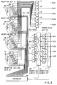
- FIG. 4 shows the connection states in the first and second connection circuits 50 and 70 in this case.
- step S20 the antenna with the second highest reception power level for the fifth channel is found.
- the reception power level of third antenna 13 is second highest.
- the controller 90 controls the connection in the first connection circuit 50 so that the transmission data TxD1 to TxD5 of respective channels input to the first to fifth input terminals may be supplied to the transmitters 61 to 65 of the associated channels and also the transmission data TxD5 of the duplex assignment channel (fifth channel with the maximum value being the predetermined level of less) may be supplied to the sixth transmitter 66.
- step S24 the controller 90 controls the connection in the second connection circuit 70 so that the outputs from the transmitters 61 to 65 of respective channels may be supplied to the transmission synthesis circuits connected to the antennas with which the reception signals of highest levels of respective channels were obtained and also the transmission signal of the duplex assignment channel (the fifth channel; however, this fifth channel being referred to as "fifth prime (5') channel" since the signal in this channel has been diversion-modulated with use of a code different from the original one), which is the output from the auxiliary transmitter 66, may be supplied to the transmission synthesis circuit connected to the antenna with which the second highest reception power level of fifth channel was obtained.
- the fifth channel the fifth channel; however, this fifth channel being referred to as "fifth prime (5') channel" since the signal in this channel has been diversion-modulated with use of a code different from the original one
- the transmission signals of the first and fifth channels which have been output from the transmitters 61 and 65, are supplied to the transmission synthesis circuit 82 for second antenna 12.
- the transmission signals of the second and third channels synthesized by the transmission synthesis circuit 81 and supplied via the transmission/reception switching circuit 21 is transmitted to the space from the antenna 11.
- the transmission signals of the first and fifth channels synthesized by the transmission synthesis circuit 82 and supplied via the transmission/reception switching circuit 22 is transmitted to the space from the antenna 12.
- the transmission signals of the fourth and fifth prime (5') channels synthesized by the transmission synthesis circuit 83 and supplied via the transmission/reception switching circuit 23 are transmitted to the space from the antenna 13. No transmission signal is radiated from the antenna 14 since the reception signal of the maximum reception power level was not obtained for any of the channels.
- the transmission signals of the respective channels are transmitted via the antennas with maximum reception power levels, and the transmission signal of the channel with the maximum reception power level being the predetermined level or less is transmitted also via the antenna with the second highest reception power level. Accordingly, the possibility of selecting the optimal antenna increases and as a result the communication quality is enhanced.
- each mobile station is provided with two receivers so as to receive two diversity-modulated transmission signals from the base station.
- a plurality of antennas are provided and a transmission signal from a mobile station is received by plural antennas. Based on reception results, one of the antennas (propagation paths) which has a highest communication quality is found and transmission to the mobile station is carried out via this antenna. If communication qualities of all propagation paths have deteriorated, it is determined that the upward propagation path from the mobile station to the base station interferes with another channel and detection precision of parameters indicating the communication quality of each path has lowered.
- the auxiliary transmitter is also used for the channel with the maximum reception power level being the predetermined level or less, two kinds of coding processes are performed, and the obtained signals are transmitted from different antennas.
- the possibility of selecting the optimal antenna increases and as a result the communication quality can be enhanced. Since the auxiliary transmitter is used, the traffic of other channels is not affected. Since two antennas are assigned to only the channel with the maximum reception power level being the predetermined level or less, the channel is not unnecessarily occupied, nor is the power consumption increased.
- the present invention is not limited to the above embodiment.
- the auxiliary transmitter 66 is used only in the case where there is a possibility of occurrence of inter-channel interference and an ordinary diversity control is insufficient. However, irrespective of whether or not the maximum reception power level is the predetermined level or less, the auxiliary transmitter 66 may always be used for the channel with a lowest maximum reception power level and two different coding processes are always carried out for one channel for transmission.
- auxiliary transmitters 66 are not limited to one. If two or more auxiliary transmitters 66 are provided, there is no problem even if two or more channels have maximum reception power levels being a predetermined level or less.
- the number of terminals of second connection circuits 70 connected to the same antenna i.e. the number of terminals of the output terminal group, is not limited to three. Needless to say, the invention can be worked if the number is two or more.
- reception power levels from the reception units 31 to 34 are used by the controller 90 as parameters for determining the transmission antenna assignment.
- the same advantage can be obtained even if the transmission antenna assignment is determined, for example, on the basis of a signal/noise ratio of a desired signal to noise of interference by another channel, a so-called CN ratio, or CI ratio.
- parameters for finding the optimal transmission antenna and parameters for finding the channel for which the auxiliary transmitter is used are the same (reception electric field intensity).
- the reception electric field intensity may be used on the one hand, and the signal/noise ratio on the other.
- the transmitters 61 to 66 were described as having two functions: a diffusion modulation function using diffusion codes, and a frequency conversion function of frequency-converting a D/A converted analog transmission signal to a radio-frequency signal.
- the invention can be worked even if these functions are separated.
- diffusion modulators may be provided at the positions of transmitters 61 to 66 in FIG. 1, and frequency converters may be provided between the transmission synthesis circuits 81 to 84 and transmission/reception switching circuits 21 to 24.
- transmission for at least one channel is carried out via two antennas. If two or more auxiliary transmitters are provided, transmission may be carried out via tree or more antennas.
- the CDMA system was adopted as an example of the multi-channel access system. However, TDMA (Time Division Multiple Access) system or FDMA (Frequency Division Multiple Access) may be adopted.
- TDMA Time Division Multiple Access
- FDMA Frequency Division Multiple Access
- one antenna has one propagation path. If one antenna is provided with plural propagation paths, one of the paths may be selected. In this case, the number of antennas may be one.
- transmitters the number of which is greater than the number of channels, are provided in a radio communication apparatus of a diversity transmission system.
- signal transmission is carried out from plural antennas via plural transmitters.
- the communication quality can be enhanced without lowering the frequency use efficiency.
Landscapes
- Engineering & Computer Science (AREA)
- Computer Networks & Wireless Communication (AREA)
- Signal Processing (AREA)
- Radio Transmission System (AREA)
- Mobile Radio Communication Systems (AREA)
Applications Claiming Priority (3)
| Application Number | Priority Date | Filing Date | Title |
|---|---|---|---|
| JP8324965A JPH10163936A (ja) | 1996-12-05 | 1996-12-05 | 無線通信装置 |
| JP324965/96 | 1996-12-05 | ||
| PCT/JP1997/004473 WO1998025357A1 (fr) | 1996-12-05 | 1997-12-05 | Dispositif de radiocommunication d'un systeme de transmission en diversite |
Publications (2)
| Publication Number | Publication Date |
|---|---|
| EP0884862A1 true EP0884862A1 (fr) | 1998-12-16 |
| EP0884862A4 EP0884862A4 (fr) | 1999-10-27 |
Family
ID=18171610
Family Applications (1)
| Application Number | Title | Priority Date | Filing Date |
|---|---|---|---|
| EP97946820A Withdrawn EP0884862A4 (fr) | 1996-12-05 | 1997-12-05 | Dispositif de radiocommunication d'un systeme de transmission en diversite |
Country Status (4)
| Country | Link |
|---|---|
| US (1) | US6396821B1 (fr) |
| EP (1) | EP0884862A4 (fr) |
| JP (1) | JPH10163936A (fr) |
| WO (1) | WO1998025357A1 (fr) |
Cited By (4)
| Publication number | Priority date | Publication date | Assignee | Title |
|---|---|---|---|---|
| WO2000076095A1 (fr) * | 1999-06-03 | 2000-12-14 | Nokia Corporation | Essai d'un emetteur-recepteur radio |
| WO2002093819A1 (fr) * | 2001-05-16 | 2002-11-21 | Qualcomm Incorporated | Procede et appareil destines a attribuer des ressources a un systeme de communication a entrees et sorties multiples (mimo) |
| WO2003058871A1 (fr) * | 2002-01-08 | 2003-07-17 | Qualcomm Incorporated | Attribution de ressources pour systemes de communication mimo-ofdm |
| CN1826819B (zh) * | 2003-06-30 | 2010-06-09 | 诺基亚公司 | 用于对从多个天线开始的加权发送进行调度的系统和相关方法 |
Families Citing this family (9)
| Publication number | Priority date | Publication date | Assignee | Title |
|---|---|---|---|---|
| JP3110333B2 (ja) * | 1997-01-23 | 2000-11-20 | 埼玉日本電気株式会社 | Tdma方式無線装置の送信ダイバシチー回路 |
| FI980035A7 (fi) * | 1998-01-09 | 1999-07-10 | Nokia Corp | Menetelmä antennikeilan suuntaamiseksi ja lähetinvastaanotin |
| JP3649374B2 (ja) * | 1998-11-30 | 2005-05-18 | ソニー株式会社 | アンテナ装置及びカード状記憶媒体 |
| US6775260B1 (en) * | 1999-02-25 | 2004-08-10 | Texas Instruments Incorporated | Space time transmit diversity for TDD/WCDMA systems |
| US7079809B1 (en) * | 2002-02-07 | 2006-07-18 | Kathrein-Werke Kg | Systems and methods for providing improved wireless signal quality using diverse antenna beams |
| JP3913575B2 (ja) * | 2002-02-28 | 2007-05-09 | 三洋電機株式会社 | 無線装置、無線通信システム、空間パス制御方法および空間パス制御プログラム |
| US20060052065A1 (en) * | 2002-06-14 | 2006-03-09 | Gideon Argaman | Transmit diversity fo base stations |
| JP5310070B2 (ja) * | 2009-02-19 | 2013-10-09 | 日本電気株式会社 | 無線通信装置、無線通信方法及び無線通信システム |
| US10720953B1 (en) | 2019-05-30 | 2020-07-21 | Shure Acquisition Holdings, Inc. | Scalable diversity deployment for wide tuning range transceiver |
Family Cites Families (8)
| Publication number | Priority date | Publication date | Assignee | Title |
|---|---|---|---|---|
| JPH07105753B2 (ja) * | 1985-05-21 | 1995-11-13 | 株式会社東芝 | スペースダイバーシチ方式 |
| US5303240A (en) * | 1991-07-08 | 1994-04-12 | Motorola, Inc. | Telecommunications system using directional antennas |
| JP3356852B2 (ja) | 1993-08-02 | 2002-12-16 | 住友電気工業株式会社 | 酸化物超電導線材の製造方法 |
| JP2876517B2 (ja) * | 1994-02-16 | 1999-03-31 | 松下電器産業株式会社 | Cdma/tdd方式基地局装置およびcdma/tdd方式移動局装置およびcdma/tdd方式無線通信システムおよびcdma/tdd方式無線通信方法 |
| US5940452A (en) * | 1995-11-29 | 1999-08-17 | Motorola, Inc. | Dual mode radio subscriber unit having a diversity receiver apparatus and method therefor |
| US6006075A (en) * | 1996-06-18 | 1999-12-21 | Telefonaktiebolaget L M Ericsson (Publ) | Method and apparatus for transmitting communication signals using transmission space diversity and frequency diversity |
| JP3111906B2 (ja) * | 1996-07-17 | 2000-11-27 | 日本電気株式会社 | 無線基地局装置 |
| US6055230A (en) * | 1997-09-05 | 2000-04-25 | Metawave Communications Corporation | Embedded digital beam switching |
-
1996
- 1996-12-05 JP JP8324965A patent/JPH10163936A/ja active Pending
-
1997
- 1997-12-05 EP EP97946820A patent/EP0884862A4/fr not_active Withdrawn
- 1997-12-05 WO PCT/JP1997/004473 patent/WO1998025357A1/fr not_active Ceased
- 1997-12-05 US US09/101,974 patent/US6396821B1/en not_active Expired - Fee Related
Non-Patent Citations (2)
| Title |
|---|
| No further relevant documents disclosed * |
| See also references of WO9825357A1 * |
Cited By (19)
| Publication number | Priority date | Publication date | Assignee | Title |
|---|---|---|---|---|
| US7062235B2 (en) | 1999-06-03 | 2006-06-13 | Nokia Corporation | Testing of a radio transceiver |
| WO2000076095A1 (fr) * | 1999-06-03 | 2000-12-14 | Nokia Corporation | Essai d'un emetteur-recepteur radio |
| EP1830509A2 (fr) | 2001-05-16 | 2007-09-05 | QUALCOMM Incorporated | Procédé et appareil destinés à attribuer des ressources à un système de communication à entrées et sorties multiples (mimo) |
| US7907972B2 (en) | 2001-05-16 | 2011-03-15 | Qualcomm Incorporated | Method and apparatus for allocating downlink resources in a multiple-input multiple-output (MIMO) communication system |
| JP2004535106A (ja) * | 2001-05-16 | 2004-11-18 | クゥアルコム・インコーポレイテッド | 多入力多出力(mimo)通信システムでリソースを割当てる方法および装置 |
| US8489107B2 (en) | 2001-05-16 | 2013-07-16 | Qualcomm Incorporated | Method and apparatus for allocating downlink resources in a multiple-input multiple-output (MIMO) communication system |
| US6662024B2 (en) | 2001-05-16 | 2003-12-09 | Qualcomm Incorporated | Method and apparatus for allocating downlink resources in a multiple-input multiple-output (MIMO) communication system |
| US7248879B1 (en) | 2001-05-16 | 2007-07-24 | Qualcomm Incorporated | Method and apparatus for allocating downlink resources in a multiple-input multiple-output (MIMO) communication system |
| WO2002093819A1 (fr) * | 2001-05-16 | 2002-11-21 | Qualcomm Incorporated | Procede et appareil destines a attribuer des ressources a un systeme de communication a entrees et sorties multiples (mimo) |
| CN100505607C (zh) * | 2001-05-16 | 2009-06-24 | 高通股份有限公司 | 多输入多输出(mimo)通信系统内分配资源的方法和装置 |
| EP1830509A3 (fr) * | 2001-05-16 | 2009-04-08 | QUALCOMM Incorporated | Procédé et appareil destinés à attribuer des ressources à un système de communication à entrées et sorties multiples (mimo) |
| AU2002360839C1 (en) * | 2002-01-08 | 2009-01-22 | Qualcomm Incorporated | Method and apparatus for a MIMO-OFDM communication system |
| AU2002360839B2 (en) * | 2002-01-08 | 2008-07-03 | Qualcomm Incorporated | Method and apparatus for a MIMO-OFDM communication system |
| CN100385843C (zh) * | 2002-01-08 | 2008-04-30 | 高通股份有限公司 | Mimo-ofdm通信系统的资源分配 |
| WO2003058871A1 (fr) * | 2002-01-08 | 2003-07-17 | Qualcomm Incorporated | Attribution de ressources pour systemes de communication mimo-ofdm |
| US8094625B2 (en) | 2002-01-08 | 2012-01-10 | Qualcomm Incorporated | Resource allocation for MIMO-OFDM communication systems |
| US8406200B2 (en) | 2002-01-08 | 2013-03-26 | Qualcomm Incorporated | Resource allocation for MIMO-OFDM communication systems |
| US7020110B2 (en) | 2002-01-08 | 2006-03-28 | Qualcomm Incorporated | Resource allocation for MIMO-OFDM communication systems |
| CN1826819B (zh) * | 2003-06-30 | 2010-06-09 | 诺基亚公司 | 用于对从多个天线开始的加权发送进行调度的系统和相关方法 |
Also Published As
| Publication number | Publication date |
|---|---|
| WO1998025357A1 (fr) | 1998-06-11 |
| JPH10163936A (ja) | 1998-06-19 |
| US6396821B1 (en) | 2002-05-28 |
| EP0884862A4 (fr) | 1999-10-27 |
Similar Documents
| Publication | Publication Date | Title |
|---|---|---|
| US6226508B1 (en) | Transmission diversity apparatus | |
| EP2175572B1 (fr) | Appareil et méthode pour transmision et réception | |
| US7627298B2 (en) | Wireless communication method with data rate selected based on interference | |
| FI86124B (fi) | Radiosaendarmottagarsystem. | |
| KR100333426B1 (ko) | 셀룰러 시스템 | |
| US6396821B1 (en) | Radio communication apparatus of diversity transmission system | |
| JPH08293846A (ja) | 送受信装置 | |
| US7020445B1 (en) | Wireless base station system, and wireless transmission method | |
| JPH08307333A (ja) | 送信ダイバシティ方式 | |
| KR20050032277A (ko) | 이동통신의 다중입력 다중출력 시스템에 적용되는데이터의 변조 및 코딩 방식 제어 방법 | |
| US7069041B2 (en) | Radio terminal apparatus and its reception control program | |
| WO1997008909A1 (fr) | Procede de lissage de la charge de trafic d'une station fixe dans un systeme de radiocommunications cellulaire et systeme de radiocommunications cellulaire | |
| US20070115910A1 (en) | Radio communication system and transmitter | |
| EP1641158A1 (fr) | Systeme de transmission radioelectrique a ondes porteuses multiples, dispositif emetteur et dispositif recepteur | |
| EP1044516B1 (fr) | Emetteur a mode tstd limitant la puissance de transmission d'une antenne et procede de controle associe pour une station de base dans un systeme de communications mobiles | |
| US20030068993A1 (en) | Radio base station apparatus and radio communication method | |
| KR100691627B1 (ko) | 다중 포트 기반의 mimo 안테나 수신기 | |
| US7342943B2 (en) | Radio base station and method of controlling radio communications | |
| US5903841A (en) | System and method for simplified handoff operation in a cellular mobile communication system | |
| WO1999039454A1 (fr) | Procede et systeme de diversite liaison descendante dans une radiotransmission | |
| US7206562B2 (en) | Cross polarized wave interference eliminating system and method | |
| JPS6328145A (ja) | 無線通信方式 | |
| EP1292049A2 (fr) | Station de base et procédé de commande de communications radio avec de l'émission en diversité | |
| JP3402426B2 (ja) | ダイバーシチ送信装置および方法 | |
| KR100486523B1 (ko) | 이동통신 시스템의 변파 중계기 |
Legal Events
| Date | Code | Title | Description |
|---|---|---|---|
| PUAI | Public reference made under article 153(3) epc to a published international application that has entered the european phase |
Free format text: ORIGINAL CODE: 0009012 |
|
| 17P | Request for examination filed |
Effective date: 19980721 |
|
| AK | Designated contracting states |
Kind code of ref document: A1 Designated state(s): DE FR GB |
|
| A4 | Supplementary search report drawn up and despatched |
Effective date: 19990910 |
|
| AK | Designated contracting states |
Kind code of ref document: A4 Designated state(s): DE FR GB |
|
| RIC1 | Information provided on ipc code assigned before grant |
Free format text: 6H 04B 7/06 A, 6H 04B 7/26 B, 6H 04L 1/06 B, 6H 04B 7/04 B |
|
| 17Q | First examination report despatched |
Effective date: 20040301 |
|
| RIC1 | Information provided on ipc code assigned before grant |
Ipc: 7H 04B 7/04 A |
|
| STAA | Information on the status of an ep patent application or granted ep patent |
Free format text: STATUS: THE APPLICATION IS DEEMED TO BE WITHDRAWN |
|
| 18D | Application deemed to be withdrawn |
Effective date: 20040712 |