EP0885097B1 - Procede et appareil de decoupage de placages - Google Patents
Procede et appareil de decoupage de placagesInfo
- Publication number
- EP0885097B1 EP0885097B1 EP97914872A EP97914872A EP0885097B1 EP 0885097 B1 EP0885097 B1 EP 0885097B1 EP 97914872 A EP97914872 A EP 97914872A EP 97914872 A EP97914872 A EP 97914872A EP 0885097 B1 EP0885097 B1 EP 0885097B1
- Authority
- EP
- European Patent Office
- Prior art keywords
- flitch
- staylog
- veneer
- collet dogs
- retain
- Prior art date
- Legal status (The legal status is an assumption and is not a legal conclusion. Google has not performed a legal analysis and makes no representation as to the accuracy of the status listed.)
- Expired - Lifetime
Links
Images




Classifications
-
- B—PERFORMING OPERATIONS; TRANSPORTING
- B27—WORKING OR PRESERVING WOOD OR SIMILAR MATERIAL; NAILING OR STAPLING MACHINES IN GENERAL
- B27L—REMOVING BARK OR VESTIGES OF BRANCHES; SPLITTING WOOD; MANUFACTURE OF VENEER, WOODEN STICKS, WOOD SHAVINGS, WOOD FIBRES OR WOOD POWDER
- B27L5/00—Manufacture of veneer ; Preparatory processing therefor
- B27L5/02—Cutting strips from a rotating trunk or piece; Veneer lathes
- B27L5/04—Cutting strips from a rotating trunk or piece; Veneer lathes the trunk being rotated about an axis lying outside it or about an axis which does not correspond to the axis of the trunk
-
- B—PERFORMING OPERATIONS; TRANSPORTING
- B25—HAND TOOLS; PORTABLE POWER-DRIVEN TOOLS; MANIPULATORS
- B25B—TOOLS OR BENCH DEVICES NOT OTHERWISE PROVIDED FOR, FOR FASTENING, CONNECTING, DISENGAGING, OR HOLDING
- B25B5/00—Clamps
- B25B5/003—Combinations of clamps
-
- B—PERFORMING OPERATIONS; TRANSPORTING
- B25—HAND TOOLS; PORTABLE POWER-DRIVEN TOOLS; MANIPULATORS
- B25B—TOOLS OR BENCH DEVICES NOT OTHERWISE PROVIDED FOR, FOR FASTENING, CONNECTING, DISENGAGING, OR HOLDING
- B25B5/00—Clamps
- B25B5/06—Arrangements for positively actuating jaws
- B25B5/08—Arrangements for positively actuating jaws using cams
- B25B5/087—Arrangements for positively actuating jaws using cams actuated by a hydraulic or pneumatic piston
-
- B—PERFORMING OPERATIONS; TRANSPORTING
- B25—HAND TOOLS; PORTABLE POWER-DRIVEN TOOLS; MANIPULATORS
- B25B—TOOLS OR BENCH DEVICES NOT OTHERWISE PROVIDED FOR, FOR FASTENING, CONNECTING, DISENGAGING, OR HOLDING
- B25B5/00—Clamps
- B25B5/14—Clamps for work of special profile
- B25B5/147—Clamps for work of special profile for pipes
-
- B—PERFORMING OPERATIONS; TRANSPORTING
- B27—WORKING OR PRESERVING WOOD OR SIMILAR MATERIAL; NAILING OR STAPLING MACHINES IN GENERAL
- B27L—REMOVING BARK OR VESTIGES OF BRANCHES; SPLITTING WOOD; MANUFACTURE OF VENEER, WOODEN STICKS, WOOD SHAVINGS, WOOD FIBRES OR WOOD POWDER
- B27L5/00—Manufacture of veneer ; Preparatory processing therefor
- B27L5/004—Cutting strips from a conical surface
-
- B—PERFORMING OPERATIONS; TRANSPORTING
- B27—WORKING OR PRESERVING WOOD OR SIMILAR MATERIAL; NAILING OR STAPLING MACHINES IN GENERAL
- B27L—REMOVING BARK OR VESTIGES OF BRANCHES; SPLITTING WOOD; MANUFACTURE OF VENEER, WOODEN STICKS, WOOD SHAVINGS, WOOD FIBRES OR WOOD POWDER
- B27L5/00—Manufacture of veneer ; Preparatory processing therefor
- B27L5/06—Cutting strips from a stationarily- held trunk or piece by a rocking knife carrier, or from rocking trunk or piece by a stationarily-held knife carrier; Veneer- cutting machines
Definitions
- the present invention relates to methods and apparatus for retaining a flitch on a staylog according to the preambles of claims 1, 5, 9, 13 and 16.
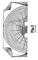
- Preparing logs for veneering begins in the sawmill. This milling process, known as "flitching", takes place on either a circular saw or a bandsaw. Traditionally, the veneer logs have been sawn at the mill to remove the log's natural taper so that the logs are left somewhat squared at the butt end, leaving substantially no taper remaining in the log from top to bottom, as opposed to from side to side, and from the small end to the butt end - substantially all of the taper from the top to the bottom having been removed from the butt end of the log. See Figs. 1 & 2. This squaring up process results in the removal of valuable veneer wood from the butt end of the veneer log.
- the squared up veneer log is then sawn in half lengthwise, and two flitches are thereby produced.
- the two flitches may or may not be of the same thickness, but each squared up flitch will hold substantially the same longitudinal thickness from top to bottom from its small end to its butt end. See Fig. 2.
- Fifty or more flitches are placed in a vat of water at a veneer mill to be heated in preparation for slicing. They are then extracted, a few at a time, and mounted one at a time on the rotary-staylog of a conventional rotary-staylog veneer slicing machine by any number of conventional dogging (attachment) systems.
- the typical rotary-staylog has a cast iron body that extends the length of the cutting surface of a veneer-slicing knife.
- the rotary-staylog body is fixed between the lathe centers of the head stock and the tail stock of the machine and rotates between them, as would a woodturning in a conventional lathe.
- the preferred dogging systems in use to attach a squared up flitch to a conventional rotary-staylog veneer slicing machine require that at least two parallel grooves be cut into the flat underside of the flitch (Fig. 2), each of a sufficient size to receive a plurality of pairs of hydraulically driven clamping dogs that are spaced along the entire length of and extend about 25.4 mm (1 in.) above the rotary-staylog's mounting surface.
- the pairs of clamping dogs engage the flitch within the grooves when the flitch is laid flush upon the rotary staylog's mounting surface and pinch the flitch between the grooves to secure the flitch to the rotary-staylog.
- WO 96/38273 A discloses a method of retaining a flitch on a flitch table, the flitch table having a plurality of pin dogs, the method comprising the steps of providing a flitch having a first plurality of holes, positioning the pin dogs in the first plurality of holes, and moving the flitch and the plurality of pin dogs into engagement to retain the flitch.
- the methods for cutting veneer sheets from a tapered flitch of the present invention allow full utilization of the natural taper of a veneer log from nearly the first cut of the veneer slicing knife, which results in superior veneer cuts, more consistent thickness of the resulting veneer sheets, no shimming out on the veneer sheets, and a much higher yield due to more of the flitch's outer surface and inner core being cut into veneer sheets.
- the methods of the present invention generate an unsliceable core of approximately 12.7 mm (1/2in.) thickness at its thickest point. The result is that 12.7 mm (1/2in.) more per flitch may be cut into veneer sheets than by the conventional methods of the prior art.
- apparatus for retaining a tapered flitch on the staylog of a veneer slicing machine with the outer surface and veneer producing zone of the tapered flitch substantially parallel to the veneer slicing knife.
- the apparatus for retaining a tapered flitch on the staylog of a veneer slicing machine of the present invention comprises the features of claims 9 or 13 or 16.
- the present invention is not limited to use on rotary staylogs of rotary-staylog veneer slicing machines, such as the one illustrated and described below, and may be incorporated into a reciprocating veneer slicer.
- the novel method and apparatus for cutting veneer sheets from a tapered flitch of the present invention requires different flitching techniques than those used in the prior art. Rather than removing substantially all of the top to bottom taper from a veneer log in the squaring up process performed in the sawmill, the method and apparatus of the present invention requires the sawyer to just barely engage the veneer log on all four sides and along its entire length -- that is, the sawyer keeps to the outside of the log By so doing, once the log has been faced on all four sides, the veneer log will still retain substantially all of its natural taper. See Fig. 3.
- each tapered flitch will have at least 25.4 mm (1 in.) of natural taper from one end of the flitch to the other, with some tapered flitches having as much as 76.2 mm (3in.) of natural taper.
- the amount of natural taper in the flitches will vary from species to species, with the greatest taper occurring in the sun-loving, more open grown species, such as walnut and white oak, and the least taper occurring in the deep woods species, such as red oak and cherry.
- the most preferred apparatus to date for putting into practice the novel method of the present invention for attaching a naturally tapered flitch to a rotary-staylog such that the veneer producing face of the naturally tapered flitch is placed in a stable, parallel relationship with the veneer slicing knife is the apparatus hereinafter referred to as the collet-dogging rotary staylog 10, which is illustrated in Figs. 4-15 with dovetail ends 11 mounted thereon that correspond to the end spindles of the lathe to which the staylog 10 will be mounted.
- the collet-dogging rotary staylog 10 differs significantly from the rotary staylogs of the prior art in the manner in which it secures a tapered flitch to the stay-log.
- the collet-dogging rotary staylog 10 of the present invention requires reworking of the conventional rotary staylogs as follows.
- the dogs of the novel collet-dogging rotary staylog 10 of the present invention for attaching a tapered flitch 16 (shown in dashed lines) to staylog 10 are hydraulically actuated collet dogs 12 that extend approximately 76.2 mm (3 in.) above the mounting surface 14 of the rotary staylog 10, as compared to the dogging clamps of the prior art that project a mere 25.4 mm (1 in.) or less above the mounting surfaces of the staylogs of the prior art.
- the depths of the holes 18 are selectively sized such that the top end of each of the collet dogs 12 makes contact with the bottom of the corresponding hole 18 in the tapered flitch when the tapered flitch 16 is lowered onto the rotary-staylog 10.
- the holes 18 to be bored into the flat underside of the tapered flitch 16 before it is mounted on the staylog 10 may be excavated by means of a series of drills that have been arranged in such a way as to bore the holes 18 in one upward plunge cut in to the flat underside of the tapered flitch 16.
- the positioning of the resulting holes along the underside of the tapered flitch 16 correspond to the positioning of the collet dogs 12 on the mounting surface 14 of the rotary-staylog 10.
- a typical boring machine consists of a steel frame which supports a surface table) on which to place the tapered flitch 16 flat underside down.
- the small end 20 of the tapered flitch rests on a gate that adjusts either up or down until the top curved surface of the tapered flitch is level from the small end 20 to the large end 22. Once the leveling has been achieved, the height that the flitch's small end rests above the table is noted, and the depth of the drills' upward plunge is adjusted accordingly. All of the drill assemblies are arranged on a steel frame mounted under the flitch supporting table so that, when activated by mechanical means, the steel frame slowly raises and the required pattern of holes is bored into the flat underside of the tapered flitch at precisely the correct depth.
- the depth of the holes 18 in the flat underside of the tapered flitch varies from the shallow 1.6 mm (1/16 in.) on the small end 20 of the tapered flitch 16 to as much as 76.2 mm (3 in.) on the large or butt end 22 of the tapered flitch 16 - these measurements being determined by the extent of the natural taper in the tapered flitch 16.
- the depth of the holes in the small end can be adjusted to provide for any desired minimum depth.
- the tapered flitch 16 is hoisted from the boring machine and lowered onto the collet dogs 12 on the mounting surface 14 of the rotary-staylog 10 until the pockets 18 have bottomed out on the tops of the collet dogs 12, as illustrated in Figs. 4 and 5. As illustrated in Fig 5. the tapered flitch does not lie flush against the mounting surface 14 of rotary staylog 10, as would a squared up flitch mounted on a rotary staylog of the prior art.
- the top curved surface of the tapered flitch 16 is level from the small end 20 to the large end 22, and thus the veneer producing face of the naturally tapered flitch 16 is in a substantially parallel relationship with the mounting surface 14 and thus the veneer slicing knife.
- the tapered flitch 16 is held stable in this position when hydraulic cylinders 24 are activated and the collet dogs 12, which are attached to the hydraulic cylinders 24, expand within the holes 18 of the tapered flitch 16 to thereby secure the tapered flitch 16 in place on the rotary-staylog 10 (Figs. 4 & 5).
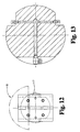
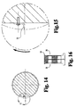
- each collet dog 12 includes a circular collet collar 26 that has been sectioned into 4 independent quadrants (Fig. 11).
- the 4 independent quadrants of collet collar 26 are held in circular disposition by steel hose clamps 26, which are sufficiently elastic to permit the 4 quadrants of collet collar 26 to expand outwardly, but not beyond the elastic limit of the steel from which the clamps 26 are constructed, so that the clamps 26 will return the collet collar 26 to its original disposition, as illustrated in Fig. 10.
- Each quadrant of the collet collar 26 has a base flange 30 by which the 4 quadrants of each collet collar 26 are retained on the mounting surface 14 of the rotary staylog 10 in cooperation with a circular steel cap 32.
- Spaces 34 are provided between each circular steel cap 32 and each collet collar 26 and its base flanges 30 to allow for the expansion outwardly of the 4 quadrants of collet collar 26.
- each collet collar 26 within each collet collar 26 is a steel plunger 36, which is attached to hydraulic cylinder 24 by means of a threaded connection 38 to the piston 40 of the hydraulic cylinder 24.
- Hydraulic cylinder 24 is hydraulically powered and controlled by conventional means.
- the conventional hydraulic connections to each of the hydraulic cylinders 24 for each of collet dogs 12 of the preferred staylog 10 of the present invention are well illustrated in the Figs.
- shallow knurling 48 has been provided to the outer surfaces of the 4 quadrants of each collet collar to provide additional grip between the collet collars and the pockets 18 of tapered flitch 16.
- a slight flair 50 may be provided to the topmost portion of each of the 4 quadrants of each collet collar 26 to provide additional gripping power between the collet collars 26 and the pockets 18 of tapered flitch 16.
- the tapered flitch 16 as it is positioned on the rotary-staylog 10 relative to the veneer cutting knife, has its entire curved outer face from which veneer will be cut substantially parallel to the veneer cutting knife's edge.
- the knife advances toward the spinning tapered flitch 16 and first engages the flitch 16, the knife will be cutting the entire length of the tapered flitch 16 due to the fact that the entire length of curved outer surface of the tapered flitch 16 is aligned with the veneer cutting knife.
- the veneer cutting knife cuts along the entire length of the tapered flitch 16 from the very first cut and from the very first veneer sheet produced thereby.
- the width of the butt end of the sheets would be increased as is shown by the dotted lines representing slices D, E, F, and G from where they extend below the line which represents the point 203.2 mm (8 in.) below the top of the tapered flitch.
- the entire width gained below the 203.2 mm (8 in.) line is due to the retention of the veneer log's natural taper. The gain in sheet width depends on the extent of the taper.
- the lines below the 203.2 mm (8 in.) line represent the butt end of a tapered flitch with a 25.4 mm (1 in.) taper, a 50.8 mm (2 in.) taper, and a 76.2 mm (3 in.) taper.
- the solid arced line between dotted lines F and G represents the last sheet that could be recovered from a squared up flitch that is being sliced on a machine of the prior art.
- the area between that solid arced line and the solid arced line below the dotted line represents the additional veneer recoverable due to the ability to reduce the required depth of engagement of the collet dogs in relation to the small end of the tapered flitch.
- a novel cut alarm indicator mounted to the rotary staylog 10 that serves to warn the lathe operator that the collet dogs 12 will strike the veneer knife's edge within a few more revolutions of the rotary staylog 10.
- Flexible tab 52 which will make an audible noise when struck by the veneer knife, may be adjusted up or down to suit the operators wishes.
- the overall quality of the veneer is enhanced in several ways by utilizing the novel method and apparatus of the present invention.
- the first sheets off the knife are full flitch length, not short and tapered.
- the heartwood tends to come in along the full length of the sheets at the same time rather than start at the butt end and slowly work its way up. This enables the user to get valuable full length sheets much sooner than the present methods of veneer cutting.
- the first half of the veneer coming off the tapered flitch is generally free of heart defects, but trees do not grow without limbs and sooner or later the knots appear. At about the same time that the knots appear, the sheets' butt end begins to widen due to the taper being left in the flitch. This additional width not only increases the yield for the veneer producer, but it also allows the end user or export veneer producer the option to clip out the knots by holding to the edge of the sheet.
- the method of attachment i.e. collet dogging method versus the grooved method, allows the tapered flitch to remain steady through the cut and thereby avoid shim sheets. The stability of cut is also greatly enhanced because the tapered flitch is resting fully on the ends of the collet dogs.
- the volume of veneer produced from each log is increased as follows, referring again to Fig. 17.
- the "b” section represents the yield increase due to the downsizing of the residual core from at least 25.4 mm (1 in.) to as little as 12.7 mm (1/2 in.)
- the "y"'s, "o”'s, and “p”'s represent the yield increase due to the inclusion of the taper: “y"'s equal 1 in. taper; “o”' s and “y”'s equal 50.8 mm (2 in.) taper; “p"'s, "o”'s, and “y”'s equal 76.2 mm (3 in.) taper.
Landscapes
- Engineering & Computer Science (AREA)
- Life Sciences & Earth Sciences (AREA)
- Manufacturing & Machinery (AREA)
- Wood Science & Technology (AREA)
- Forests & Forestry (AREA)
- Mechanical Engineering (AREA)
- Manufacture Of Wood Veneers (AREA)
Claims (18)
- Procédé pour maintenir un plot (16) sur une barre de sciage ou staylog (10) pour découper un placage à partir du plot (16), la barre de sciage (16) ayant une pluralité de moyens de griffe (12), comprenant les étapes consistant à fournir un plot (16) ayant une pluralité de trous (18) pour recevoir une pluralité de moyens de griffe (12), et positionner la pluralité de moyens de griffe (12) à l'intérieur de la pluralité de trous (18) dans le plot, caractérisé en ce que lesdits moyens de griffe sont des griffes de serrage à pince extensibles (12), et par l'étape supplémentaire consistant à étendre lesdites griffes de serrage à pince extensibles pour maintenir le plot (16) sur la barre de sciage (10).
- Procédé selon la revendication 1, dans lequel l'étape d'extension inclut des moyens permettant d'étendre de façon hydraulique les griffes de serrage à pince (12) pour maintenir le plot (16) sur la barre de sciage (10).
- Procédé selon la revendication 2, dans lequel l'étape d'extension inclut en outre un moletage (48) sur les surfaces des griffes de serrage à pince (12) qui vient en prise avec le plot (16) pour maintenir le plot (16) sur la barre de sciage (10).
- Procédé selon la revendication 3, dans lequel l'étape d'extension inclut en outre un évasement (50) sur les surfaces supérieures des griffes de serrage à pince (12) qui vient également en prise avec le plot (16) pour maintenir le plot (16) sur la barre de sciage (10).
- Procédé pour maintenir un plot (16) sur une barre de sciage ou staylog (10) pour découper un placage à partir du plot (16), la barre de sciage (16) ayant une pluralité de moyens de griffe (12), comprenant les étapes consistant à fournir un plot (16) ayant une pluralité de trous (18) pour recevoir une pluralité de moyens de griffe (12), et positionner la pluralité de moyens de griffe (12) dans la pluralité de trous (18), caractérisé en ce que lesdits moyens de griffe sont des griffes de serrage à pince (12), les trous (18) ayant un profil de profondeur et les griffes de serrage à pince (12) ayant des parties pour la mise en prise du plot configurées pour s'adapter généralement au profil de profondeur; et par une étape supplémentaire de mise en prise du plot (16) avec les griffes de serrage à pince (12) pour maintenir le plot (16) sur la barre de sciage (10), une zone de production de placage étant maintenue en relation parallèle avec une lame de découpe de placage.
- Procédé selon la revendication 5, dans lequel l'étape de mise en prise inclut des moyens permettant d'étendre de façon hydraulique les griffes de serrage à pince (12) pour maintenir le plot (16) sur la barre de sciage (10).
- Procédé selon la revendication 6, dans lequel l'étape de mise en prise inclut en outre un moletage (48) sur les surfaces des griffes de serrage à pince (12) qui vient en prise avec le plot (16) pour maintenir le plot (16) sur la barre de sciage (10).
- Procédé selon la revendication 7, dans lequel l'étape de mise en prise inclut en outre un évasement (50) sur les surfaces supérieures des griffes de serrage à pince (12) qui vient également en prise avec le plot (16) pour maintenir le plot (16) sur la barre de sciage (10).
- Appareil permettant de maintenir un plot (16) avec une face de production de placage conique sur la surface de montage d'une barre de sciage (10) pour un mouvement devant une lame de découpe de placage, comprenant des moyens de griffe (12) s'étendant à partir de la surface de montage (14) de la barre de sciage (10) pour venir en prise avec le plot (16), caractérisé en ce que lesdits moyens de griffe sont des griffes de serrage à pince (12), ledit appareil comprenant en outre des moyens permettant d'étendre les griffes de serrage à pince (12) lorsqu'elles viennent en prise avec le plot (16) pour maintenir le plot (16) sur la barre de sciage (10), la face de production de placage conique du plot (16) étant en relation parallèle avec la lame de découpe de placage, de manière à réduire au minimum la quantité de déchets de placage provenant de la face de production de placage conique du plot (16).
- Appareil selon la revendication 9, dans lequel les moyens d'extension incluent un moletage (48) sur les surfaces des griffes de serrage à pince (12) qui vient en prise avec le plot (16) pour maintenir le plot (16) sur la barre de sciage (10).
- Appareil selon la revendication 10, dans lequel les moyens d'extension incluent en outre un évasement (50) sur les surfaces supérieures des griffes de serrage à pince (12) qui vient également en prise avec le plot (16) pour maintenir le plot (16) sur la barre de sciage (10).
- Appareil selon la revendication 9, comprenant en outre des moyens permettant de faire retentir une alarme pour le cas où, lors du mouvement continu de la face de production de placage devant une lame de découpe de placage, la lame de découpe de placage entrerait en contact avec les griffes de serrage à pince (12).
- Appareil permettant de maintenir un plot sur une barre de sciage, le plot comprenant une pluralité de trous (18) formés dans la surface inférieure plate de celui-ci, comprenant une barre de sciage (10) pour supporter un plot (16), une pluralité de moyens de griffe (12) attachés à la barre de sciage (10) et positionnés pour être reçus par la pluralité de trous (18) formés dans la surface inférieure plate du plot (16) pour venir en prise avec le plot (16), caractérisé en ce que lesdits moyens de griffe sont des griffes de serrage à pince (12), ledit appareil comprenant en outre des moyens d'extension des griffes de serrage à pince (12) lorsqu'elles viennent en prise avec le plot (16) pour maintenir le plot (16) sur la barre de sciage (10).
- Appareil selon la revendication 13, dans lequel les moyens d'extension incluent un moletage (48) sur les surfaces des griffes de serrage à pince (12) qui vient en prise avec le plot (16) pour maintenir le plot (16) sur la barre de sciage (10).
- Appareil selon la revendication 14, dans lequel les moyens d'extension incluent en outre un évasement (50) sur les surfaces supérieures des griffes de serrage à pince (12) qui vient également en prise avec le plot (16) pour maintenir le plot (16) sur la barre de sciage (10).
- Appareil permettant de maintenir un plot pour le découper, comprenant une barre de sciage (10) ayant une surface de montage avec une pluralité d'emplacements prédéterminés, et une pluralité de moyens de griffe (12), situés au niveau des emplacements prédéterminés pour venir en prise avec le plot (16) pour maintenir le plot (16) sur la barre de sciage (10), caractérisé en ce que lesdits moyens de griffe sont des griffes de serrage à pince (12), et en ce que la distance entre la surface de montage et le plot (16) au niveau d'un emplacement prédéterminé est proportionnelle à l'épaisseur du plot (16) au niveau de l'emplacement prédéterminé.
- Appareil selon la revendication 16, dans lequel les griffes de serrage à pince comprennent en outre un moletage (48) sur les surfaces des griffes de serrage à pince (12) qui vient en prise avec le plot (16) pour maintenir le plot (16) sur la barre de sciage (10).
- Appareil selon la revendication 17, dans lequel les griffes de serrage à pince comprennent en outre un évasement (50) sur les surfaces des griffes de serrage à pince (12) qui vient en prise avec le plot (16) pour maintenir le plot (16) sur la barre de sciage (10).
Applications Claiming Priority (3)
| Application Number | Priority Date | Filing Date | Title |
|---|---|---|---|
| US1303596P | 1996-03-08 | 1996-03-08 | |
| US13035P | 1996-03-08 | ||
| PCT/US1997/003425 WO1997032699A1 (fr) | 1996-03-08 | 1997-03-07 | Procede et appareil de decoupage de placages |
Publications (3)
| Publication Number | Publication Date |
|---|---|
| EP0885097A1 EP0885097A1 (fr) | 1998-12-23 |
| EP0885097A4 EP0885097A4 (fr) | 2004-05-19 |
| EP0885097B1 true EP0885097B1 (fr) | 2006-10-04 |
Family
ID=21757974
Family Applications (1)
| Application Number | Title | Priority Date | Filing Date |
|---|---|---|---|
| EP97914872A Expired - Lifetime EP0885097B1 (fr) | 1996-03-08 | 1997-03-07 | Procede et appareil de decoupage de placages |
Country Status (5)
| Country | Link |
|---|---|
| US (1) | US5865232A (fr) |
| EP (1) | EP0885097B1 (fr) |
| BR (1) | BR9707956A (fr) |
| DE (1) | DE69736773T2 (fr) |
| WO (1) | WO1997032699A1 (fr) |
Families Citing this family (3)
| Publication number | Priority date | Publication date | Assignee | Title |
|---|---|---|---|---|
| US5868187A (en) | 1995-05-31 | 1999-02-09 | Capital Machine Company, Inc. | Method and apparatus for retaining a flitch for cutting |
| US6474379B1 (en) | 1999-12-16 | 2002-11-05 | Merritt Plywood Machinery, Inc. | Automatic flitch planer |
| WO2005102633A2 (fr) * | 2004-04-15 | 2005-11-03 | Miller Veneers, Inc. | Procede et appareil pour decouper des feuilles de placage a partir d'un quartelot |
Family Cites Families (26)
| Publication number | Priority date | Publication date | Assignee | Title |
|---|---|---|---|---|
| US793306A (en) * | 1904-04-04 | 1905-06-27 | Louis Koss | Veneer-slicer. |
| US2676627A (en) * | 1948-10-18 | 1954-04-27 | Johnson City Foundry & Machine | Veneer slicer |
| US2576520A (en) * | 1948-11-04 | 1951-11-27 | Capital Machine Company | Hydraulic control of veneer slicing machines |
| US2862540A (en) * | 1954-02-01 | 1958-12-02 | Ryan Aeronautical Co | Expanding clamp for a tube bending machine |
| GB1130510A (en) * | 1965-03-08 | 1968-10-16 | Capital Machine Co | A method of obtaining water-stain-free veneer |
| US3654973A (en) * | 1970-10-19 | 1972-04-11 | Capital Machine Co | Hydraulically controlled pressure cap |
| US3680612A (en) * | 1971-03-17 | 1972-08-01 | Capital Machine Co | Extension dog system for veneer slicer |
| US3808925A (en) * | 1973-03-12 | 1974-05-07 | Durand Machine Co Ltd | Rotary veneer clipper |
| US3905408A (en) * | 1974-03-29 | 1975-09-16 | Capital Machine Co | Vacuum flitch table for veneer slicer |
| IT1039407B (it) * | 1975-06-26 | 1979-12-10 | Cremona Angelo | Dispositivo per l allontanamento e successivo avvicinamento rapido del gruppo porta lama e porta barra al tronco dopo ogni operazione di taglio in una trinciatrice verticale o pressocche verticale |
| IT1039408B (it) * | 1975-06-26 | 1979-12-10 | Cremona Angelo | Dispositivo di traslazione dei gruppi porta lama e porta barra di una tranciatrice di tronchi di legno verticale o pressocche verticale |
| US4392519A (en) * | 1981-02-05 | 1983-07-12 | Calvert Manufacturing, Inc. | Knife pitch control for veneer lathe |
| DE3147688A1 (de) * | 1981-12-02 | 1983-06-16 | M.A.N. Maschinenfabrik Augsburg-Nürnberg AG, 8000 München | "rohr-schnellspannvorrichtung" |
| US4503896A (en) * | 1982-07-30 | 1985-03-12 | Capital Machine Company, Inc. | Dog system for veneer slicer |
| US4587616A (en) * | 1983-05-31 | 1986-05-06 | David R. Webb Co., Inc. | Control system for veneer slicer |
| US4601317A (en) * | 1985-01-31 | 1986-07-22 | Capital Machine Company, Inc. | Veneer slicing system |
| US4683926A (en) * | 1986-04-01 | 1987-08-04 | David R. Webb Co., Inc. | Slicer dogs for thirds and quarters |
| US5143129A (en) * | 1989-09-18 | 1992-09-01 | Raute Oy Of Vesijarvenkatu | Apparatus for adjusting the pitch angle of a knife blade in a veneer lathe |
| IT1249595B (it) * | 1991-02-12 | 1995-03-09 | Cremona Angelo & Figlio | Stazione di taglio in fogli per sfogliati di legno |
| US5150746A (en) * | 1991-05-17 | 1992-09-29 | David R. Webb Co., Inc. | Flitch table |
| US5101874A (en) * | 1991-05-17 | 1992-04-07 | David R. Webb Co., Inc. | Tangential rotary slicer |
| US5381841A (en) * | 1991-05-17 | 1995-01-17 | David R. Webb Co., Inc. | Tangential rotary slicer |
| US5333658A (en) * | 1993-08-26 | 1994-08-02 | Premier Gear & Machine Works | Veneer lathe |
| US5385184A (en) * | 1994-01-18 | 1995-01-31 | Merritt Plywood Machinery, Inc. | Vacuum holding device for a veneer slicer |
| US5694995A (en) * | 1995-05-31 | 1997-12-09 | Capital Machine Company, Inc. | Method and apparatus for preparing a flitch for cutting |
| US5562137A (en) * | 1995-05-31 | 1996-10-08 | Capital Machine Company, Inc. | Method and apparatus for retaining a flitch for cutting |
-
1997
- 1997-03-07 US US08/813,669 patent/US5865232A/en not_active Expired - Fee Related
- 1997-03-07 EP EP97914872A patent/EP0885097B1/fr not_active Expired - Lifetime
- 1997-03-07 BR BR9707956-1A patent/BR9707956A/pt not_active IP Right Cessation
- 1997-03-07 WO PCT/US1997/003425 patent/WO1997032699A1/fr not_active Ceased
- 1997-03-07 DE DE69736773T patent/DE69736773T2/de not_active Expired - Fee Related
Also Published As
| Publication number | Publication date |
|---|---|
| EP0885097A4 (fr) | 2004-05-19 |
| DE69736773T2 (de) | 2007-08-16 |
| EP0885097A1 (fr) | 1998-12-23 |
| US5865232A (en) | 1999-02-02 |
| BR9707956A (pt) | 2000-01-04 |
| WO1997032699A1 (fr) | 1997-09-12 |
| DE69736773D1 (de) | 2006-11-16 |
Similar Documents
| Publication | Publication Date | Title |
|---|---|---|
| US7967043B2 (en) | Method and apparatus for cutting veneer sheets from a flitch | |
| US2825371A (en) | Apparatus for producing and debarking wood chips | |
| EP1075915A2 (fr) | Machine a couper en onglet | |
| US3190326A (en) | Chipper apparatus | |
| US3656521A (en) | Power chisel | |
| US5865232A (en) | Method and apparatus for cutting veneer sheets from a tapered flitch | |
| US5906231A (en) | Knife insert for a wood-working machine | |
| FI80229B (fi) | Fanersvarv. | |
| JPH0415082B2 (fr) | ||
| JPH10510489A (ja) | 切削用フリッチを保持するための方法および装置 | |
| WO1989004747A1 (fr) | Procede de sciage de bois et produits de bois ainsi realises | |
| CA1091135A (fr) | Preparation en trois etapes de grandes lamelles de bois | |
| US20040144447A1 (en) | Veneer-slicing machine | |
| US5762121A (en) | Procedure for working a tree trunk by machining | |
| US3282312A (en) | Chipper knife and apparatus | |
| US4667549A (en) | Centering device and method | |
| AU623344B2 (en) | Method of sawing timber and timber products formed thereby | |
| CA1046910A (fr) | Methode d'abattage des arbres | |
| FI13903Y1 (fi) | Puunsyöttörulla | |
| SU852261A1 (ru) | Устройство дл бесстружечного срезани дЕРЕВьЕВ | |
| JP2004113016A (ja) | 一木造りの木製植栽鉢 | |
| Vermaas | Primary processing of eucalypts and factors affecting it | |
| RU2056275C1 (ru) | Пресс-нож | |
| DE60217913D1 (de) | Verfahren zur planbearbeitung von rundholz | |
| GB2330794A (en) | Woodworking router with replaceable blades. |
Legal Events
| Date | Code | Title | Description |
|---|---|---|---|
| PUAI | Public reference made under article 153(3) epc to a published international application that has entered the european phase |
Free format text: ORIGINAL CODE: 0009012 |
|
| 17P | Request for examination filed |
Effective date: 19980925 |
|
| AK | Designated contracting states |
Kind code of ref document: A1 Designated state(s): DE IT |
|
| A4 | Supplementary search report drawn up and despatched |
Effective date: 20040406 |
|
| RIC1 | Information provided on ipc code assigned before grant |
Ipc: 7B 27L 5/06 B Ipc: 7B 27L 5/04 A |
|
| 17Q | First examination report despatched |
Effective date: 20040707 |
|
| GRAP | Despatch of communication of intention to grant a patent |
Free format text: ORIGINAL CODE: EPIDOSNIGR1 |
|
| GRAS | Grant fee paid |
Free format text: ORIGINAL CODE: EPIDOSNIGR3 |
|
| GRAA | (expected) grant |
Free format text: ORIGINAL CODE: 0009210 |
|
| AK | Designated contracting states |
Kind code of ref document: B1 Designated state(s): DE IT |
|
| PG25 | Lapsed in a contracting state [announced via postgrant information from national office to epo] |
Ref country code: IT Free format text: LAPSE BECAUSE OF FAILURE TO SUBMIT A TRANSLATION OF THE DESCRIPTION OR TO PAY THE FEE WITHIN THE PRE;WARNING: LAPSES OF ITALIAN PATENTS WITH EFFECTIVE DATE BEFORE 2007 MAY HAVE OCCURRED AT ANY TIME BEFORE 2007. THE CORRECT EFFECTIVE DATE MAY BE DIFFERENT FROM THE ONE RECORDED.SCRIBED TIME-LIMIT Effective date: 20061004 |
|
| REF | Corresponds to: |
Ref document number: 69736773 Country of ref document: DE Date of ref document: 20061116 Kind code of ref document: P |
|
| PGFP | Annual fee paid to national office [announced via postgrant information from national office to epo] |
Ref country code: DE Payment date: 20070308 Year of fee payment: 11 |
|
| PLBE | No opposition filed within time limit |
Free format text: ORIGINAL CODE: 0009261 |
|
| STAA | Information on the status of an ep patent application or granted ep patent |
Free format text: STATUS: NO OPPOSITION FILED WITHIN TIME LIMIT |
|
| 26N | No opposition filed |
Effective date: 20070705 |
|
| PGFP | Annual fee paid to national office [announced via postgrant information from national office to epo] |
Ref country code: IT Payment date: 20070521 Year of fee payment: 11 |
|
| PG25 | Lapsed in a contracting state [announced via postgrant information from national office to epo] |
Ref country code: DE Free format text: LAPSE BECAUSE OF NON-PAYMENT OF DUE FEES Effective date: 20081001 |
|
| PG25 | Lapsed in a contracting state [announced via postgrant information from national office to epo] |
Ref country code: IT Free format text: LAPSE BECAUSE OF NON-PAYMENT OF DUE FEES Effective date: 20080307 |