EP0885157B1 - Kettenförderer - Google Patents
Kettenförderer Download PDFInfo
- Publication number
- EP0885157B1 EP0885157B1 EP97942748A EP97942748A EP0885157B1 EP 0885157 B1 EP0885157 B1 EP 0885157B1 EP 97942748 A EP97942748 A EP 97942748A EP 97942748 A EP97942748 A EP 97942748A EP 0885157 B1 EP0885157 B1 EP 0885157B1
- Authority
- EP
- European Patent Office
- Prior art keywords
- chain
- clips
- roller chain
- conveyer according
- base part
- Prior art date
- Legal status (The legal status is an assumption and is not a legal conclusion. Google has not performed a legal analysis and makes no representation as to the accuracy of the status listed.)
- Expired - Lifetime
Links
- 239000013013 elastic material Substances 0.000 claims description 2
- 238000010276 construction Methods 0.000 claims 2
- 238000004519 manufacturing process Methods 0.000 description 2
- 239000000463 material Substances 0.000 description 2
- 229910000831 Steel Inorganic materials 0.000 description 1
- XAGFODPZIPBFFR-UHFFFAOYSA-N aluminium Chemical compound [Al] XAGFODPZIPBFFR-UHFFFAOYSA-N 0.000 description 1
- 229910052782 aluminium Inorganic materials 0.000 description 1
- 238000005452 bending Methods 0.000 description 1
- 230000005540 biological transmission Effects 0.000 description 1
- 230000006378 damage Effects 0.000 description 1
- 230000001419 dependent effect Effects 0.000 description 1
- 238000005516 engineering process Methods 0.000 description 1
- 239000004810 polytetrafluoroethylene Substances 0.000 description 1
- 229920001343 polytetrafluoroethylene Polymers 0.000 description 1
- 239000010959 steel Substances 0.000 description 1
Images


Classifications
-
- B—PERFORMING OPERATIONS; TRANSPORTING
- B65—CONVEYING; PACKING; STORING; HANDLING THIN OR FILAMENTARY MATERIAL
- B65G—TRANSPORT OR STORAGE DEVICES, e.g. CONVEYORS FOR LOADING OR TIPPING, SHOP CONVEYOR SYSTEMS OR PNEUMATIC TUBE CONVEYORS
- B65G1/00—Storing articles, individually or in orderly arrangement, in warehouses or magazines
- B65G1/02—Storage devices
- B65G1/04—Storage devices mechanical
- B65G1/06—Storage devices mechanical with means for presenting articles for removal at predetermined position or level
-
- F—MECHANICAL ENGINEERING; LIGHTING; HEATING; WEAPONS; BLASTING
- F16—ENGINEERING ELEMENTS AND UNITS; GENERAL MEASURES FOR PRODUCING AND MAINTAINING EFFECTIVE FUNCTIONING OF MACHINES OR INSTALLATIONS; THERMAL INSULATION IN GENERAL
- F16G—BELTS, CABLES, OR ROPES, PREDOMINANTLY USED FOR DRIVING PURPOSES; CHAINS; FITTINGS PREDOMINANTLY USED THEREFOR
- F16G13/00—Chains
- F16G13/02—Driving-chains
Definitions
- the invention relates to a chain conveyor according to the preamble of claim 1.
- the chain conveyors in question here are generally used in storage compartments of rack storage systems, where they serve as funding for the goods to be stored.
- the grant is usually about two redirections to an endless funding looped, being the actual funding a conveyor chain provided with rollers is provided.
- Pallets are usually used as a base for the goods to be stored for use. When the goods are stored, the latter are opened put the conveyor chain and, mostly from a forklift, in pushed the shelf in. If necessary, the goods from this Forklift also pulled out.
- This is provided with a roller chain, whose idlers in pairs on both sides by a pair of Side tabs are connected, with every second link of the Chain is designed as a bracket on which the stored Goods can be supported.
- the side tabs are in place so far down that they are the top strand of the roller chain can lead laterally along the track, the The width of the running rail is smaller than the distance of the two side straps of a pair. Points in the lower area the aluminum running track has a return channel in which the lower run of the roller chain is accommodated, is guided and supported vertically.
- the chain section that is between the when inserting the pallet and the one already stored Goods is subject to high levels of thrust.
- the pallet that is being pushed in exercises one Pulling force on the chain section behind it, which is led around the front deflection. Because such diversions however, for reasons of space, a very small diameter have, they have a poor efficiency and are suitable not for high pulling forces.
- the one deflected around the deflection Chain hoist is attached to the rear deflection via the elastic webbing transmitted, which further deteriorates the efficiency, taking into account that the mass of the stored Goods can be up to 20 tons.
- GB-A-495894 discloses two further embodiments of chains known.
- the embodiment shown in FIGS. 1 to 5 shows a chain through two differently designed types of tabs is formed.
- Both Tab types are U-shaped, with one tab at least by Double the wall thickness is wider than the other tab, making the wider tab can enclose the narrower tab laterally.
- the narrower of these tabs is on the Provide the top with two rollers, which run through the base part extend and protrude the tabs on the top.
- the two types of tabs are hinged together. In the stretched condition of the chain the end faces of the tabs lie against each other.
- each tab consists of two Sides.
- One type of tab has rounded ends and is at each end provided with a hole. There is an L-shape between the two holes designed stop is provided.
- the other type of tab is trapezoidal and each with a hole.
- the ends of this second type of tab are formed as projections, which are stretched by such Place the link-designed chain on the respective stop of the adjacent link and enable the transmission of thrust.
- the intended idlers also protrude the top of the respective tab.
- Preferred embodiments of the invention are in the dependent ones Claims 2 to 9 circumscribed.
- Another object of the invention is a chain conveyor propose the one with means for lateral guidance the roller chain is formed, which is simply arranged and can be manufactured inexpensively, the guide means with very low frictional resistance between roller chain and Carrier rail should come up.
- the tab stanchions 13 provided which each of the recording of a shaft Connection of the tabs 1 and for storage and support of Serve idlers.
- the base part 10 of the tab 1 is with two along the one Leg 11 arranged recesses 16 provided the Width b2 is greater than the wall thickness of a leg 11, 12 is. Through these recesses 16 is the joining of several, uniformly designed plates 1 to form a chain favored by a leg 11, 12 of a previous or following tab, rotated by 180 ° around the vertical axis 1 engages in such a recess 16.
- the base part 10 is also transverse to its longitudinal axis extending slot 15 provided.
- This slot 15 is used Inclusion of a driver made of an elastic material, as explained in more detail below with reference to FIG. 2a becomes.
- the basic shape of such a tab 1 is preferably by Stamping made while the U-shaped design was made then bending the punched part is generated.
- the two end regions 17, 18 of the base part 10 of a tab 1 are preferably formed obliquely. On the other hand, they can both end areas of the base part are also provided with a step be, as indicated by broken lines L is indicated.
- One leg 12 is the top of the base part with two 10 protruding elevations 14 provided, from manufacturing technology For reasons of the shorter area 17a, 18a of the base part 10 adjacent legs 12 such elevations 14th having.
- This guide element 2 is a guide element 2 for the roller chain in three different views.
- This guide element 2 essentially consists of a guide plate 21 and a clamping part 24.
- the lower region 26 of the guide plate 21 is used for lateral guidance of the roller chain while the guide plate 21 on the top of a support surface 25, which in a rotating chain to Supporting the lower chain center is formed. How it works this guide plate 21 is based on the Fig. 3 explained in more detail.
- the driver 19 in an elevation, a side elevation as well as a floor plan.
- the preferably made of rubber Driver 19 serves as a support for to be supported on the tabs Goods.
- the driver 19 has a holding part 15 on, which is designed to correspond to this slot.
- the holding part 15 is guided through the slot and the driver is then rotated by 90 °.
- the driver 19 slightly protrudes the elevations of the tab, so that light goods are not on the surveys but on the Carrier on. Due to the elastic design of the driver 19 However, it is ensured that heavy goods Squeeze drivers together and stand up on the surveys, which creates a secure, non-positive connection between Secured lug and goods to be stored-pallet is.
- the mounting rail 5 has on the top a tread 6 offset upwards, which laterally is delimited by two guide surfaces.
- On the bottom is the mounting rail 5 with a cavity H open at the bottom provided, in which two auxiliary rails 7 are arranged, on which the guide plates 21 of the guide elements 2 with their Support surfaces 25 rest and the lower chain strand 8b vertically support.
- the roller chain 8 is replaced by a plurality of according to FIG. 1 trained tabs 1 and support rollers 3 are formed, each two tabs articulated to one another by means of a shaft 28 are connected.
- the shafts 28 are also used for storage the support rollers 3.
- Through the respective shaft 28 is a Passed guide element 2, which the tab 1 on the protrudes one side down. Reaches in on the other side the clamping part 24 of the guide element 2 the leg 12a, whereby both the shaft 28 and the guide element 2 be fixed in the position shown here.
- a Securing bolt 29 are provided, which is anchored in a self-locking manner is.
- the roller chain 8 In order to form a chain from the uniform plates 1, are alternately rotated by 180 ° around their vertical axis arranged, the one opposite the other tab, in Seen longitudinal direction of the roller chain, in each case the wall thickness a leg of a tab is offset.
- the guide elements 2 In addition to the tabs 1 are also the guide elements 2 alternately by 180 ° arranged twisted, i.e. in other words, the leadership elements 2 are alternately once from the left and once from pushed right through the respective shaft 28, so that the roller chain 8 guided on both sides of the tread 6 becomes.
- the strip 23 of the guide element 2 extends along the underside of the respective leg of a tab, and prevents twisting of the guide element 2, the height the bar 23 approximately the wall thickness of a leg of a tab equivalent. It should be added that the roller chain 8 is only approx. Makes up 60% of the circulating funding, while the rest 40% consist of a webbing attached to the two chain ends is fixed.
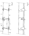
- FIG. 4 shows a top view of a section of a roller chain, which with uniform tabs 1 according to FIG. 1 and Guide elements 2 according to FIG. 2 is provided. From this illustration it can be seen that the tabs 1a, 1b, 1c, 1d alternately are rotated by 180 ° around their vertical axis, and that the one opposite the other tab 1a, 1b, 1c, 1d, seen in the longitudinal direction of the roller chain 8 to each Wall thickness of a leg of a tab 1a, 1b, 1c, 1d offset - Is, so that each one leg 11, 12 of a tab in the recess 16 (Fig. 1) in the base part of the adjacent tab intervenes.
- This design allows the tabs 1a, 1b, 1c, 1d, can also absorb and transmit lateral forces.
- the average length L of the base part 10 at least approximately the center distance A between two corresponds to adjacent idlers 3.
- the base part 10 is preferably 0.5 to 3 mm shorter than the center distance between two adjacent idlers 3, so that in the stretched Condition of the chain between the end faces of neighboring base parts 10b, 10c from adjacent tabs 1b, 1c also Gap b in the order of magnitude of 0.5 to 3 mm arises.
- This Training causes mutual, over a predetermined Rotational movement of adjacent tabs beyond the angle is limited by turning back the Tab the end faces of adjacent base parts together. It is important in this context that the end faces Corresponding base parts from adjacent tabs are trained. Such a trained roller chain can therefore transmit thrust without the risk of that the chain folds up on individual sections.
- FIG. 5 shows the section of the roller chain according to FIG. 4 in one Side view. From this illustration they are alternate arranged guide elements 2 can be seen which the tabs protrude downwards.
- a chain conveyor designed in this way is very simple built up and can be manufactured cheaply, because both the tabs as well as the guide elements are formed uniformly are. By providing attacks that prevent the mutual, Rotational movement beyond a predetermined angle adjacent tabs in the previously described Limit way, the roller chain can also transmit thrust.
Landscapes
- Engineering & Computer Science (AREA)
- Mechanical Engineering (AREA)
- General Engineering & Computer Science (AREA)
- Chain Conveyers (AREA)
- Framework For Endless Conveyors (AREA)
- Escalators And Moving Walkways (AREA)
- Lubrication Of Internal Combustion Engines (AREA)
- Devices For Conveying Motion By Means Of Endless Flexible Members (AREA)
Description
Diese Aufgabe wird durch die im Kennzeichen des Anspruchs 1 aufgeführten Merkmale gelöst.
- Fig. 1 bis 3
- eine einzelne Lasche für eine Rollenkette in drei unterschiedlichen Ansichten;
- Fig. 4 bis 6
- ein Führungselement für die Rollenkette in drei unterschiedlichen Ansichten;
- Fig. 7 bis 9
- einen Mitnehmer für die Rollenkette in drei unterschiedlichen Ansichten;
- Fig. 10
- einen Querschnitt durch eine Tragschiene sowie durch die Rollenkette.
- Fig. 11
- eine Draufsicht auf einen Abschnitt einer Rollenkette, welche mit Laschen gemäss den Fig. 1 bis 3 versehen ist;
- Fig. 12
- den Abschnitt der Rollenkette gemäss Fig. 11 in einer Seitenansicht;
Claims (15)
- Kettenförderer mit einer Rollenkette (8) und einer Tragschiene (5) zum vertikalen Abstützen der Rollenkette (8), wobei die Rollenkette (8) eine Vielzahl von Tragrollen (3) aufweist, welche mittels Laschen (1) miteinander verbunden sind, und wobei die Laschen (1) Anschläge aufweisen, welche die gegenseitige, Ober einen vorbestimmten Winkel hinausgehende Drehbewegung benachbarter Laschen (1) derart begrenzen, dass die Rollenkette (8) Schubkräfte übertragen kann, dadurch gekennzeichnet, dass die Laschen (1) zwei Schenkel (11, 12) mit einem dazwischen liegenden Basisteil (10) aufweisen, dessen mittlere Länge (L) zumindest annähernd dem Achsabstand (A) von zwei benachbarten Tragrollen (3) entspricht, dass die Stirnseiten (17, 18) benachbarter Basisteile (10) von benachbarten Laschen (1) korrespondierend ausgebildet sind und als Anschläge wirken, und dass der Basisteil (10) mit zwei entlang eines Schenkels (11, 12) angeordneten Aussparungen (16) versehen ist, deren Breite (b) grösser ist als die Wandstärke eines Schenkels (11, 12).
- Kettenförderer nach Anspruch 1, dadurch gekennzeichnet, dass der überwiegende Teil der Laschen (1) U-förmig ausgebildet ist.
- Kettenförderer nach Anspruch 2, dadurch gekennzeichnet, dass im gestreckten Zustand der Rollenkette (8), zwischen den Stirnseiten benachbarter Laschen, ein Spalt (b) von weniger als 5% der Länge einer Lasche (1) besteht.
- Kettenförderer nach Anspruch 2 oder 3, dadurch gekennzeichnet, dass der Basisteil (10) der Laschen (1) als obere Abdeckung der Rollenkette (8) ausgebildet ist und im gestreckten Zustand der Rollenkette (8) sowohl die Tragrollen (4) wie auch die Tragschiene (5) vor Verschmutzung schützen.
- Kettenförderer nach einem der Ansprüche 2 bis 4, dadurch gekennzeichnet, dass die beiden Endbereiche (17, 18) des Basisteils (10) einer Lasche (1) eine Stufung aufweisen und/oder schräg ausgebildet sind.
- Kettenförderer nach Anspruch 5, dadurch gekennzeichnet, dass die Laschen (1) einstückig ausgebildet sind, und dass der dem kürzeren Bereich (17a, 18a) des Basisteils (10) angrenzende Schenkel (12) mit einer die Oberseite des Basisteils (10) überragenden Erhebung (14) versehen ist.
- Kettenförderer nach einem der Ansprüche 2 bis 6, dadurch gekennzeichnet, dass der Basisteil (10) der Laschen (1) auf der Oberseite als Auflagefläche für auf der Rollenkette (8) zu fördernde Güter ausgebildet ist.
- Kettenförderer nach einem der vorhergehenden Ansprüche, dadurch gekennzeichnet, dass die Rollenkette (8) aus einheitlichen Laschen (1) besteht, welche eine von einer zentralsymmetrischen Gestaltung abweichende Geometrie aufweisen, und dass die Laschen (1a, 1b, 1c, 1d) wechselweise um 180° um ihre Hochachse verdreht angeordnet sind, wobei die eine gegenüber der anderen Lasche (1a, 1b, 1c, 1d), in Längsrichtung der Rollenkette (8) gesehen, um jeweils die Wandstärke eines Schenkels (11, 12) einer Lasche (1) versetzt ist.
- Kettenförderer nach einem der vorhergehenden Ansprüche, dadurch gekennzeichnet, dass der Basisteil (10) mit einem quer zur Bewegungsrichtung der Rollenkette (8) verlaufenden Schlitz (15) versehen ist, und dass ein aus einem elastischen Material gefertigter Mitnehmer (19) vorgesehen ist, welcher mit einem korrespondierend zu diesem Schlitz ausgebildeten Halteteil (20) versehen ist, der durch den Schlitz (15) führbar und durch eine anschliessen Drehung um 90° im Basisteil (10) fixierbar ist.
- Kettenförderer nach Anspruch 1, wobei die Laschen (1) der Rollenkette (8) mittels einer Welle (28) gelenkig miteinander verbunden sind, und wobei die Welle (28) gleichzeitig als Tragachse für die Tragrollen (3) ausgebildet ist, dadurch gekennzeichnet, dass die Welle (28) hohl ist, und dass durch die Welle (28) ein diskret ausgebildetes Führungselement (2) hindurchgeführt ist, welches die Lasche (10) zumindest auf einer Seite nach unten zur Führungsschiene (5) hin überragt.
- Kettenförderer nach Anspruch 10, dadurch gekennzeichnet, dass das Führungselement (2) mit einer zur Lasche (10) zu richtenden Leiste (23) versehen ist, welche sich entlang der Unterseite des Schenkels einer Lasche (10) erstreckt, wobei die Höhe der Leiste (23) maximal der Wandstärke eines Schenkels (11, 12) einer Lasche (10) entspricht.
- Kettenförderer nach Anspruch 10 oder 11, dadurch gekennzeichnet, dass die Tragschiene (5) auf der Oberseite eine Lauffläche (6) aufweist, welche seitlich von zwei tiefer liegenden Führungsflächen (31, 32) begrenzt wird, und dass jedes Führungselement (2) zumindest ein seitliches Führungsglied (21) aufweist, welches mit den Führungsflächen (31, 32) zusammenzuarbeiten bestimmt ist.
- Kettenförderer nach einem der Ansprüche 10 bis 12, dadurch gekennzeichnet, dass die Führungselemente (2) aus einem Kunststoff gefertigt sind, welcher gute, selbstschmierende Eigenschaften aufweist.
- Kettenförderer nach einem der Ansprüche 10 bis 13, mit endseitig angeordneten Umlenkvorrichtungen zum Umlenken der Rollenkette (8) und zur Unterteilung derselben in ein oberes und ein unteres Kettentrum (8a, 8b), wobei die Tragschiene (5) auf ihrer Unterseite einen das untere Kettentrum (8b) zumindest teilweise aufnehmenden Hohlraum (H) aufweist, dadurch gekennzeichnet, dass die Führungselemente (2) die Laschen (1) des oberen Kettentrums (8a) sowohl nach unten zur Führungsschiene (5) hin wie auch zumindest auf einer Seite überragen, wobei der die Laschen (1) nach unten überragende Bereich (26) der Führungselemente (2) zur Führung des oberen Kettentrums (8a) ausgebildet ist, und wobei das Führungselement (2) in dem die Laschen (1) seitlich überragenden Bereich eine Führungsfläche (25) zur Führung und vertikalen Abstützung des unteren, zumindest teilweise im Hohlraum (H) aufgenommenen Kettentrums (8b) aufweist.
- Kettenförderer nach einem der vorhergehenden Ansprüche, dadurch gekennzeichnet, dass beide Enden der Rollenkette (8) mittels eines Gurtbandes zu einem umlaufenden, endlosen Fördermittel verbunden sind, wobei die Länge der Rollenkette (8) höchstens 60% des gesamten Fördermittels beträgt.
Applications Claiming Priority (4)
| Application Number | Priority Date | Filing Date | Title |
|---|---|---|---|
| CH2915/96 | 1996-11-27 | ||
| CH291596 | 1996-11-27 | ||
| CH02915/96A CH688587A5 (de) | 1996-11-27 | 1996-11-27 | Kettenfoerderer. |
| PCT/CH1997/000385 WO1998023507A1 (de) | 1996-11-27 | 1997-10-10 | Kettenförderer |
Publications (2)
| Publication Number | Publication Date |
|---|---|
| EP0885157A1 EP0885157A1 (de) | 1998-12-23 |
| EP0885157B1 true EP0885157B1 (de) | 2003-11-19 |
Family
ID=4244489
Family Applications (1)
| Application Number | Title | Priority Date | Filing Date |
|---|---|---|---|
| EP97942748A Expired - Lifetime EP0885157B1 (de) | 1996-11-27 | 1997-10-10 | Kettenförderer |
Country Status (10)
| Country | Link |
|---|---|
| US (1) | US6206179B1 (de) |
| EP (1) | EP0885157B1 (de) |
| JP (1) | JP2000504296A (de) |
| KR (1) | KR19990082031A (de) |
| CN (1) | CN1082927C (de) |
| AT (1) | ATE254573T1 (de) |
| AU (1) | AU724550B2 (de) |
| CH (1) | CH688587A5 (de) |
| DE (1) | DE59711032D1 (de) |
| WO (1) | WO1998023507A1 (de) |
Families Citing this family (5)
| Publication number | Priority date | Publication date | Assignee | Title |
|---|---|---|---|---|
| FI121005B (fi) * | 2007-04-13 | 2010-06-15 | Metso Paper Inc | Sivuohjauspala |
| US8479972B2 (en) * | 2010-04-16 | 2013-07-09 | Intercontinental Great Brands Llc | Expandable food carton |
| CN104209998B (zh) * | 2014-08-15 | 2016-02-17 | 浙江万江木业有限公司 | 一种锯木机的防反弹装置 |
| US10829309B1 (en) * | 2019-10-25 | 2020-11-10 | John Bean Technologiess AB | Glide strips and guide blocks for conveyors |
| GB202019717D0 (en) * | 2020-12-14 | 2021-01-27 | Ocado Innovation Ltd | Gripping device |
Family Cites Families (5)
| Publication number | Priority date | Publication date | Assignee | Title |
|---|---|---|---|---|
| GB495894A (en) | 1937-06-29 | 1938-11-22 | Boulton Aircraft Ltd | Improvements in chains for transmitting both tension and compression |
| US3708059A (en) * | 1971-10-14 | 1973-01-02 | Velten & Pulver | Convey system and attachments therefor |
| FR2512135B1 (fr) * | 1981-09-01 | 1985-09-06 | Burger Raymond | Chaine de roulement et son application pour le deplacement d'une surface en compression par rapport a une autre |
| DE8806871U1 (de) * | 1988-05-26 | 1989-06-22 | Wilcke, Hans, 53498 Bad Breisig | Schubkette mit zugehörigem Antrieb |
| ES2051680T1 (es) * | 1992-06-22 | 1994-07-01 | Zimmermann Marino | Carriles de soporte de plataformas asi como plataforma de introduccion con carriles de soporte de plataformas y via de transporte. |
-
1996
- 1996-11-27 CH CH02915/96A patent/CH688587A5/de not_active IP Right Cessation
-
1997
- 1997-10-10 US US09/101,256 patent/US6206179B1/en not_active Expired - Fee Related
- 1997-10-10 WO PCT/CH1997/000385 patent/WO1998023507A1/de not_active Ceased
- 1997-10-10 AT AT97942748T patent/ATE254573T1/de not_active IP Right Cessation
- 1997-10-10 DE DE59711032T patent/DE59711032D1/de not_active Expired - Fee Related
- 1997-10-10 AU AU44492/97A patent/AU724550B2/en not_active Ceased
- 1997-10-10 EP EP97942748A patent/EP0885157B1/de not_active Expired - Lifetime
- 1997-10-10 JP JP10524098A patent/JP2000504296A/ja active Pending
- 1997-10-10 KR KR1019980705751A patent/KR19990082031A/ko not_active Ceased
- 1997-10-10 CN CN97191898A patent/CN1082927C/zh not_active Expired - Fee Related
Also Published As
| Publication number | Publication date |
|---|---|
| AU724550B2 (en) | 2000-09-28 |
| HK1016952A1 (en) | 1999-11-12 |
| WO1998023507A1 (de) | 1998-06-04 |
| EP0885157A1 (de) | 1998-12-23 |
| ATE254573T1 (de) | 2003-12-15 |
| DE59711032D1 (de) | 2003-12-24 |
| CN1082927C (zh) | 2002-04-17 |
| JP2000504296A (ja) | 2000-04-11 |
| US6206179B1 (en) | 2001-03-27 |
| KR19990082031A (ko) | 1999-11-15 |
| CH688587A5 (de) | 1997-11-28 |
| CN1209786A (zh) | 1999-03-03 |
| AU4449297A (en) | 1998-06-22 |
Similar Documents
| Publication | Publication Date | Title |
|---|---|---|
| DE69925519T2 (de) | Förderband mit seitlicher Faltung | |
| EP0336084B1 (de) | Öffnungsabschluss, wie Tür oder Tor | |
| DE2323601C2 (de) | Lattenförderer | |
| DE3400721C2 (de) | ||
| DE2808052C2 (de) | Gliederband sowie Fördereinrichtung zum Transportieren von Gegenständen | |
| DE19839270C2 (de) | Energieführungskette | |
| DE2359541A1 (de) | Kettenfoerderer | |
| DE3615734C2 (de) | ||
| DE2237600A1 (de) | Gliederfoerderband aus gelenkig miteinander verbundenen metallischen plattengliedern | |
| DE69908362T2 (de) | Bogensegment für die förderstrecke eines kettenförderers | |
| EP3693296A1 (de) | Mehrgliedriger fördergurt mit laufrollen | |
| DE102017004820B3 (de) | Transportaufsatz, Zugmittel, Plattenförderer und Verfahren | |
| DE2105936A1 (de) | Forderer mit langgestrecktem Fuhrungs rohr und endlosem Fordergurt | |
| EP0772559B1 (de) | Kettenförderer | |
| DE2806999A1 (de) | Schienenfuehrung fuer einen fahrzeugsitz | |
| DE8900158U1 (de) | Förderband | |
| DE3906682A1 (de) | Seil-umlenkvorrichtung | |
| DE202016008741U1 (de) | Modul für ein modulares Förderband mit einer Rollenförderfläche und aus einer Mehrzahl solcher Module gebildetes modulares Förderband | |
| EP0858961A2 (de) | Förderbahn für Keilripperiemen für Stückgut, insbesondere für Gepäck-Behälter | |
| EP0154929A1 (de) | Rahmen für Bandfördervorrichtungen | |
| EP0885157A1 (de) | Kettenförderer | |
| WO1998023507A9 (de) | Kettenförderer | |
| DE2233832A1 (de) | Einrichtung zum foerdern von lasten | |
| EP0519316A1 (de) | Kragarmregal | |
| CH664341A5 (de) | Kurvengaengiger plattenbandfoerderer. |
Legal Events
| Date | Code | Title | Description |
|---|---|---|---|
| PUAI | Public reference made under article 153(3) epc to a published international application that has entered the european phase |
Free format text: ORIGINAL CODE: 0009012 |
|
| 17P | Request for examination filed |
Effective date: 19980717 |
|
| AK | Designated contracting states |
Kind code of ref document: A1 Designated state(s): AT BE CH DE DK ES FI FR GB GR IE IT LI LU MC NL PT SE |
|
| 17Q | First examination report despatched |
Effective date: 20020116 |
|
| GRAH | Despatch of communication of intention to grant a patent |
Free format text: ORIGINAL CODE: EPIDOS IGRA |
|
| RAP1 | Party data changed (applicant data changed or rights of an application transferred) |
Owner name: GILGEN LOGISTICS SYSTEMS AG |
|
| GRAS | Grant fee paid |
Free format text: ORIGINAL CODE: EPIDOSNIGR3 |
|
| GRAA | (expected) grant |
Free format text: ORIGINAL CODE: 0009210 |
|
| AK | Designated contracting states |
Kind code of ref document: B1 Designated state(s): AT BE CH DE DK ES FI FR GB GR IE IT LI LU MC NL PT SE |
|
| PG25 | Lapsed in a contracting state [announced via postgrant information from national office to epo] |
Ref country code: NL Free format text: LAPSE BECAUSE OF FAILURE TO SUBMIT A TRANSLATION OF THE DESCRIPTION OR TO PAY THE FEE WITHIN THE PRESCRIBED TIME-LIMIT Effective date: 20031119 Ref country code: IT Free format text: LAPSE BECAUSE OF FAILURE TO SUBMIT A TRANSLATION OF THE DESCRIPTION OR TO PAY THE FEE WITHIN THE PRE;WARNING: LAPSES OF ITALIAN PATENTS WITH EFFECTIVE DATE BEFORE 2007 MAY HAVE OCCURRED AT ANY TIME BEFORE 2007. THE CORRECT EFFECTIVE DATE MAY BE DIFFERENT FROM THE ONE RECORDED.SCRIBED TIME-LIMIT Effective date: 20031119 Ref country code: IE Free format text: LAPSE BECAUSE OF FAILURE TO SUBMIT A TRANSLATION OF THE DESCRIPTION OR TO PAY THE FEE WITHIN THE PRESCRIBED TIME-LIMIT Effective date: 20031119 Ref country code: GB Free format text: LAPSE BECAUSE OF FAILURE TO SUBMIT A TRANSLATION OF THE DESCRIPTION OR TO PAY THE FEE WITHIN THE PRESCRIBED TIME-LIMIT Effective date: 20031119 Ref country code: FR Free format text: LAPSE BECAUSE OF FAILURE TO SUBMIT A TRANSLATION OF THE DESCRIPTION OR TO PAY THE FEE WITHIN THE PRESCRIBED TIME-LIMIT Effective date: 20031119 Ref country code: FI Free format text: LAPSE BECAUSE OF FAILURE TO SUBMIT A TRANSLATION OF THE DESCRIPTION OR TO PAY THE FEE WITHIN THE PRESCRIBED TIME-LIMIT Effective date: 20031119 |
|
| REG | Reference to a national code |
Ref country code: GB Ref legal event code: FG4D Free format text: NOT ENGLISH |
|
| REG | Reference to a national code |
Ref country code: CH Ref legal event code: NV Representative=s name: RITSCHER & PARTNER AG PATENTANWAELTE Ref country code: CH Ref legal event code: EP |
|
| REF | Corresponds to: |
Ref document number: 59711032 Country of ref document: DE Date of ref document: 20031224 Kind code of ref document: P |
|
| REG | Reference to a national code |
Ref country code: IE Ref legal event code: FG4D Free format text: GERMAN |
|
| PG25 | Lapsed in a contracting state [announced via postgrant information from national office to epo] |
Ref country code: SE Free format text: LAPSE BECAUSE OF FAILURE TO SUBMIT A TRANSLATION OF THE DESCRIPTION OR TO PAY THE FEE WITHIN THE PRESCRIBED TIME-LIMIT Effective date: 20040219 Ref country code: GR Free format text: LAPSE BECAUSE OF FAILURE TO SUBMIT A TRANSLATION OF THE DESCRIPTION OR TO PAY THE FEE WITHIN THE PRESCRIBED TIME-LIMIT Effective date: 20040219 Ref country code: DK Free format text: LAPSE BECAUSE OF FAILURE TO SUBMIT A TRANSLATION OF THE DESCRIPTION OR TO PAY THE FEE WITHIN THE PRESCRIBED TIME-LIMIT Effective date: 20040219 |
|
| PG25 | Lapsed in a contracting state [announced via postgrant information from national office to epo] |
Ref country code: ES Free format text: LAPSE BECAUSE OF FAILURE TO SUBMIT A TRANSLATION OF THE DESCRIPTION OR TO PAY THE FEE WITHIN THE PRESCRIBED TIME-LIMIT Effective date: 20040302 |
|
| NLV1 | Nl: lapsed or annulled due to failure to fulfill the requirements of art. 29p and 29m of the patents act | ||
| GBV | Gb: ep patent (uk) treated as always having been void in accordance with gb section 77(7)/1977 [no translation filed] |
Effective date: 20031119 |
|
| REG | Reference to a national code |
Ref country code: IE Ref legal event code: FD4D |
|
| PGFP | Annual fee paid to national office [announced via postgrant information from national office to epo] |
Ref country code: DE Payment date: 20040917 Year of fee payment: 8 Ref country code: CH Payment date: 20040917 Year of fee payment: 8 |
|
| PLBE | No opposition filed within time limit |
Free format text: ORIGINAL CODE: 0009261 |
|
| STAA | Information on the status of an ep patent application or granted ep patent |
Free format text: STATUS: NO OPPOSITION FILED WITHIN TIME LIMIT |
|
| PG25 | Lapsed in a contracting state [announced via postgrant information from national office to epo] |
Ref country code: LU Free format text: LAPSE BECAUSE OF NON-PAYMENT OF DUE FEES Effective date: 20041010 Ref country code: AT Free format text: LAPSE BECAUSE OF NON-PAYMENT OF DUE FEES Effective date: 20041010 |
|
| PG25 | Lapsed in a contracting state [announced via postgrant information from national office to epo] |
Ref country code: MC Free format text: LAPSE BECAUSE OF NON-PAYMENT OF DUE FEES Effective date: 20041031 Ref country code: BE Free format text: LAPSE BECAUSE OF NON-PAYMENT OF DUE FEES Effective date: 20041031 |
|
| 26N | No opposition filed |
Effective date: 20040820 |
|
| EN | Fr: translation not filed | ||
| BERE | Be: lapsed |
Owner name: *GILGEN LOGISTICS SYSTEMS A.G. Effective date: 20041031 |
|
| PG25 | Lapsed in a contracting state [announced via postgrant information from national office to epo] |
Ref country code: LI Free format text: LAPSE BECAUSE OF NON-PAYMENT OF DUE FEES Effective date: 20051031 Ref country code: CH Free format text: LAPSE BECAUSE OF NON-PAYMENT OF DUE FEES Effective date: 20051031 |
|
| PG25 | Lapsed in a contracting state [announced via postgrant information from national office to epo] |
Ref country code: DE Free format text: LAPSE BECAUSE OF NON-PAYMENT OF DUE FEES Effective date: 20060503 |
|
| REG | Reference to a national code |
Ref country code: CH Ref legal event code: PL |
|
| BERE | Be: lapsed |
Owner name: *GILGEN LOGISTICS SYSTEMS A.G. Effective date: 20041031 |
|
| PG25 | Lapsed in a contracting state [announced via postgrant information from national office to epo] |
Ref country code: PT Free format text: LAPSE BECAUSE OF NON-PAYMENT OF DUE FEES Effective date: 20040419 |