EP0885337B1 - Verbundwerkstoff bauelement - Google Patents
Verbundwerkstoff bauelement Download PDFInfo
- Publication number
- EP0885337B1 EP0885337B1 EP97908819A EP97908819A EP0885337B1 EP 0885337 B1 EP0885337 B1 EP 0885337B1 EP 97908819 A EP97908819 A EP 97908819A EP 97908819 A EP97908819 A EP 97908819A EP 0885337 B1 EP0885337 B1 EP 0885337B1
- Authority
- EP
- European Patent Office
- Prior art keywords
- structural member
- set forth
- core
- edge strips
- gypsum
- Prior art date
- Legal status (The legal status is an assumption and is not a legal conclusion. Google has not performed a legal analysis and makes no representation as to the accuracy of the status listed.)
- Expired - Lifetime
Links
- 239000002131 composite material Substances 0.000 title description 5
- 239000011162 core material Substances 0.000 claims description 68
- 239000000463 material Substances 0.000 claims description 28
- 229910052602 gypsum Inorganic materials 0.000 claims description 27
- 239000010440 gypsum Substances 0.000 claims description 27
- 239000002184 metal Substances 0.000 claims description 19
- 239000002023 wood Substances 0.000 claims description 13
- 239000000203 mixture Substances 0.000 claims description 6
- 239000000835 fiber Substances 0.000 claims description 5
- 239000000945 filler Substances 0.000 claims description 5
- 239000004033 plastic Substances 0.000 claims description 3
- 239000011230 binding agent Substances 0.000 claims description 2
- 239000000758 substrate Substances 0.000 claims description 2
- 239000010410 layer Substances 0.000 description 16
- 239000000853 adhesive Substances 0.000 description 7
- 230000001070 adhesive effect Effects 0.000 description 7
- 238000010276 construction Methods 0.000 description 6
- 239000002002 slurry Substances 0.000 description 6
- 238000007373 indentation Methods 0.000 description 4
- 238000005192 partition Methods 0.000 description 4
- 238000004519 manufacturing process Methods 0.000 description 3
- 238000000034 method Methods 0.000 description 3
- 239000004568 cement Substances 0.000 description 2
- 238000001035 drying Methods 0.000 description 2
- 239000002356 single layer Substances 0.000 description 2
- 241000238631 Hexapoda Species 0.000 description 1
- 238000005266 casting Methods 0.000 description 1
- 239000004020 conductor Substances 0.000 description 1
- 238000010586 diagram Methods 0.000 description 1
- 230000009970 fire resistant effect Effects 0.000 description 1
- 238000009432 framing Methods 0.000 description 1
- 239000003562 lightweight material Substances 0.000 description 1
- 238000013021 overheating Methods 0.000 description 1
- 230000002093 peripheral effect Effects 0.000 description 1
- 238000004080 punching Methods 0.000 description 1
Images


Classifications
-
- E—FIXED CONSTRUCTIONS
- E04—BUILDING
- E04B—GENERAL BUILDING CONSTRUCTIONS; WALLS, e.g. PARTITIONS; ROOFS; FLOORS; CEILINGS; INSULATION OR OTHER PROTECTION OF BUILDINGS
- E04B2/00—Walls, e.g. partitions, for buildings; Wall construction with regard to insulation; Connections specially adapted to walls
- E04B2/74—Removable non-load-bearing partitions; Partitions with a free upper edge
- E04B2/7407—Removable non-load-bearing partitions; Partitions with a free upper edge assembled using frames with infill panels or coverings only; made-up of panels and a support structure incorporating posts
- E04B2/7409—Removable non-load-bearing partitions; Partitions with a free upper edge assembled using frames with infill panels or coverings only; made-up of panels and a support structure incorporating posts special measures for sound or thermal insulation, including fire protection
- E04B2/7411—Details for fire protection
-
- E—FIXED CONSTRUCTIONS
- E04—BUILDING
- E04B—GENERAL BUILDING CONSTRUCTIONS; WALLS, e.g. PARTITIONS; ROOFS; FLOORS; CEILINGS; INSULATION OR OTHER PROTECTION OF BUILDINGS
- E04B2/00—Walls, e.g. partitions, for buildings; Wall construction with regard to insulation; Connections specially adapted to walls
- E04B2/74—Removable non-load-bearing partitions; Partitions with a free upper edge
- E04B2/7407—Removable non-load-bearing partitions; Partitions with a free upper edge assembled using frames with infill panels or coverings only; made-up of panels and a support structure incorporating posts
- E04B2/7409—Removable non-load-bearing partitions; Partitions with a free upper edge assembled using frames with infill panels or coverings only; made-up of panels and a support structure incorporating posts special measures for sound or thermal insulation, including fire protection
- E04B2/7412—Posts or frame members specially adapted for reduced sound or heat transmission
-
- E—FIXED CONSTRUCTIONS
- E04—BUILDING
- E04C—STRUCTURAL ELEMENTS; BUILDING MATERIALS
- E04C3/00—Structural elongated elements designed for load-supporting
- E04C3/02—Joists; Girders, trusses, or trusslike structures, e.g. prefabricated; Lintels; Transoms; Braces
- E04C3/29—Joists; Girders, trusses, or trusslike structures, e.g. prefabricated; Lintels; Transoms; Braces built-up from parts of different material, i.e. composite structures
-
- E—FIXED CONSTRUCTIONS
- E04—BUILDING
- E04C—STRUCTURAL ELEMENTS; BUILDING MATERIALS
- E04C3/00—Structural elongated elements designed for load-supporting
- E04C3/30—Columns; Pillars; Struts
- E04C3/34—Columns; Pillars; Struts of concrete other stone-like material, with or without permanent form elements, with or without internal or external reinforcement, e.g. metal coverings
Definitions
- This invention related to structural members for use primarily in the construction of house and other buildings.
- this invention concerns a structural member comprising a non heat conducting core member, edge strips and backing material which co-operate to provide the structural member with the required strength and rigidity.
- a typical building such as a house, includes a variety of different structural or framing members. Examples are wall studs, floor and ceiling joists, roof rafters, partition wall studs, etc. These members have traditionally been made of wood, although in recent years sheet metal studs have found increasing use.
- EP 0327261 A1 discloses the building panel comprising an insulated slab having rigid channel section members positioned on the edge surfaces of the core. This structure is covered on at least one side by a shallow tray made of some rigid material such as metal, plastic or wood which is secured to the assembly of the slab and channel section member by means of an adhesive.
- DE 2917551 discloses a structural element comprising a core, two strips made of metal or other material covering two opposing surfaces, and two rigid backing plates made of wood or wood material covering the other two surfaces. This whole structure is secured by fastening means preferably in the form of metal ribbons or wire.
- a structural member for supporting at least one board comprising a non-heat conducting core member, said core member comprising a substrate material and further having first and second spaced apart sides and first and second spaced apart edge surfaces, further comprising first and second rigid edge strips, said edge strips being separated and spaced apart by said core member, further comprising one or more sheets of flexible backing material having good shear resistance, wherein the required strength and rigidity of the structural member is provided by the cooperation of said core material, said rigid edge strips and said backing material.
- a composite structural member constructed in accordance with this invention comprises a body part and multiple rigid strips which are attached to and separated by the body part.
- the body part is formed by a core having substantially flat parallel sides and opposed edges, and the opposed edges are covered by the rigid strips.
- the core is made of gypsum and the strips are made of sheet metal. Backing sheets of paper are secured to the sides.
- a wall 30 which may be a partition wall, for example, of a house or other type of building.
- the wall 30 includes a plurality of vertically extending composite studs 31 constructed in accordance with the present invention which are spaced apart in the horizontal direction.
- the studs 31 are fastened at their lower ends through a C-shaped metal floor channel 32 and are fastened at their upper ends through a C-shaped metal ceiling channel 33.
- One side of the channels and the studs 31 is covered by a board 34 and the other side is covered by a board 35, thereby forming a hollow wall since the studs 31 both separate and support the boards 34 and 35.
- the two boards 34 and 35 are gypsum wallboards.
- the stud 31 comprises a main body 41 and two rigid strips 42 and 43.
- the main body 41 includes a core 44 formed, for example, of gypsum and cover or backing sheets 45 and 46 secured to the two sides of the core 44.
- the main body 41 includes two edges 47 which are covered by the rigid edge strips 42 and 43.
- the two rigid strips 42 and 43 are preferably made of sheet metal, and in the embodiment of the invention illustrated in Figs. 1-4, the two strips 42 and 43 cover the edges 47 and each includes flanges 48 which fold or extend over the backing sheets 45 and 46.
- the strips 42 and 43 are firmly secured to the main body 41, and the boards 34 and 35 are secured to the members 31 by screw fasteners 49.
- the fasteners 49 extend through the boards 34 and 35 and self-thread through the rigid strips 42 and 43 and firmly secure the boards 34 and 35 to the strips. Since the strips are, in turn, secured to the main body 41, the boards 34 and 35 are separated by and secured to the studs 31.
- the core 44 is made of gypsum and its sides are covered by backing sheets 45 and 46 of the type normally used to cover ordinary gypsum wallboard.
- the strips 42 and 43 are made of sheet metal preferably having a minimum thickness of 0.045cm (0.0179 inch), and the flanges 48 have a length of approximately 0.64cm (1/4").
- the stud 31 constructed in accordance with this invention has a number of advantages. Its cost may be substantially less than the cost of a comparable size wood or metal stud.
- the main body 41 is relatively fire-resistant and does not conduct head readily between the two boards 34 and 35.
- the metal strips 42 and 43 cover and protect the end surfaces of the core 44 and they also form members to which screw fasteners may be firmly secured.
- the studs may have the size and feel of wood studs and may be handled with essentially the same construction techniques as wood studs.
- the stud construction shown in Figs. 3 and 4 may include a main body formed by a single sheet of gypsum shaft liner, which is normally approximately 2.54cm (1") in thickness. With the addition of the flanges 48, such a stud will have an overall thickness of approximately 2.62cm (1-1/32"). Instead, the stud shown in Figs. 3 and 4 may be formed of a single core having a standard stud size of a thickness of 3.18cm (1-1/4") and a width of 9.21cm (3-5/8").
- Fig. 5 illustrates a preferred construction wherein the main body of a stud 51 is formed by two layers 52 and 53 of 1.59cm (5/8") gypsum board. Each of the layers 52 and 53 is covered on both sides by backing sheets 54, and the edges are covered by rigid strips 55 which extend across both layers. The adjoining backing sheets 54 of the two layers 52 and 53 may be fastened together by an adhesive, and the strips 55 may be secured to the two layers 52 and 53 by an adhesive.
- Figs. 6 through 13 illustrate different methods of securing the rigid strips to the main body.
- the main body may be formed by a single layer of core material and backing sheets as shown in Fig. 4. or by two layers as illustrated in Fig. 5.
- a structural member 60 which includes a main body 61 and two edge strips 62.
- Each of the edge strips 62 includes flanges 63 as previously described, and the flanges 63 are secured to the main body 61 by crimps or indentations 64 at spaced locations along the length of the structural member 60.
- the crimps or indentations 64 are provided in place of or in addition to an adhesive between the strips and the core and the backing sheets of the main body 61.
- Fig. 7 illustrates a structural member including a main core 66 and edge strips 67 (only one shown), wherein flanges 68 of the edge strips 67 are secured to the main body 66 by staking as indicated by the numeral 69 at spaced locations along the length of the structural member.
- Fig. 8 illustrates a structural member 71 similar to the member 60 shown in Fig. 6. However, it is formed by two layers 72 and 73 instead of a single layer, and by rigid edge strips 74.
- the edge strips 74 are secured to the two layers 72 and 73 by crimps 75 similar to the structure shown in Fig. 6.
- the two layers 72 and 73 are preferably glued together and they may be fastened by an adhesive to the edge strips 74.
- Fig. 9 shows a structural member 77 including a main body 78 and two edge strips 79.
- Each edge strip 79 includes two flanges 80 which are pressed toward each other and into the sides 81 of the main body 78, thereby securing the edge strips to the main body.
- edge strips 82 are secured to a main body 83.
- Each of the edge strips 82 has two flanges 84 and each of the flanges has preformed prongs 85 formed in them at spaced locations.
- the prongs 85 may be precut by a punching operation.
- to assemble an edge strip 82 with the main body 83 the center portion of an edge strip 82 is positioned against an edge of the main body and then the flanges 84 are bent downwardly and inwardly to drive the prongs 85 into the main body 83 and secure the edge strip to the main body 83.
- the main body 88 has edge strips 89 attached to it.
- Each of the edge strips 89 includes flanges 90 and the flanges have edge portions which are bent inwardly to form flange lips 91.
- the main body 88 has grooves 92 formed along the sides 93 adjacent the edges of the main body, and the flanges 90 are bent inwardly as best shown in Fig. 13 to cause the flange lips 91 to fold into the grooves 92.
- the lips 91 extend at substantially a right angle to the adjacent portions of the flanges 90 and the grooves 92 are shaped to engage the lips 91.
- each of the grooves 92 has a surface 94 which is at a right angle to the side 93 and is engaged by the lip 91, and another surface 95 which is sloped or angled to provide clearance for the lip 91 when the flange 90 is bent inwardly.
- Figs. 14 and 15 illustrate an embodiment of the invention wherein edge strips are secured to a main body by covering it with a sheet of backing material.
- a flat strip 104 of rigid material is positioned against the edge 105 of the main body 101, and the width of the strip 104 is substantially equal to the overall width of the main body 101.
- a cover strip 106 is positioned over the strip 104, and the strip 106 is sufficiently wide that it folds over the edges of the strip 104 and onto the outer sides of the layers 102.
- the folded over portions 107 are securely fastened by an adhesive to the sheets 103 of backing material, thereby securing the edge strip 104 to the main body 101.
- edge strips 104 and strips 106 are provided along each edge of the main body 101.
- the cover strips 106 may be made of backing paper or paper treated for moisture resistance or woven fibre sheets.
- Fig. 16 illustrates a structural member including a main body 111 and edge strips 112 secured to opposed edges of the main body.
- two layers 112 of board are secured together to form the main body.
- Each edge strip 112 includes a downwardly bent flange 114 and layers 115 of adhesive secure the flanges 114 to the outer backing sheets of the layers 113.
- the center portion of each edge strip (that is the portion of the edge strip between the two flanges 114) may not be secured to the main body 111.
- the edge strips are secured to one or more layers of core material, after the core material has been formed. Normally the layers have been cut or formed into long strips.
- the core material of the main body may be extruded or cast in place and secured to the backing sheets and to the edge strips before it has set.
- a structural member 120 is formed by a core 121, two backing sheets 122 and 123 and two rigid edge strips 124.
- the core 121 is made, for example, from gypsum and may be cast in place or extruded in the shape shown in Fig. 17.
- the two rigid strips 124 are positioned against the edge surfaces 126 and then the backing sheet 122 is folded over one side 127 of the core, over the two rigid strips 124, and then over at least part of the other side 128 of the core.
- the second backing sheet 123 is then positioned against the side 128 and overlies the folded edge portions of the sheet 122.
- the rigid edge strips 124 preferably include a plurality of perforations 129 which extend through the strips.
- the perforations 129 permit the slurry, used in forming the core 121, to pass through and engage the backing sheet 122 and attain a better attachment with the backing sheet at the edges of the member.
- Figs. 21 and 22 also show two embodiments where the backing sheets and the end strips are secured to the core and backing sheets before the core slurry has finally set.
- a core 135 of, for example, gypsum slurry is formed and a backing sheet 136 is folded around one side, the edges and over a portion of the opposite side.
- a second backing sheet 137 is then applied to the other side of the core.
- the backing sheets are, of course, similar to those shown in Fig. 17-19.
- Extending along the edges of the core are two rigid edge strips 141 which have flanges 142.
- the flanges 142 angle inwardly and they extend into indentations 143 in the core 135 and the backing sheet 136, thereby forming a firm connection between the edge strips 141 and the core 135.
- the flanges 142 may be initially angled inwardly as shown in Fig. 21 before the core slurry is poured into the backing paper, or the flanges may be bent inwardly and the indentations 143 formed after the core slurry has been poured.
- a single sheet may be provided, having a width sufficiently wide that the edges overlap and form an envelope around the core.
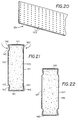
- Fig. 22 shows a structural member similar to that shown in Fig. 21 and includes a core 146 having backing sheets 147 along opposite sides, and edge strips 148 along the opposed edges.
- the structural member shown in Fig. 22 is, of course, similar to the member shown in Fig. 21 except that the backing sheets do not extend across the edges of the core and underneath the rigid strips.
- Figs. 23, 24 and 25 illustrate additional structural members incorporating the present invention.
- a cutaway view of a house 153 mounted on a foundation 154 is illustrated.
- the house includes load carrying floor joists 156, ceiling joists 157, wall studs 158, roof rafters 159, and studs 160 forming an interior partition. All of the members 156-160 may be formed by composite structural members in accordance with the present invention.
- the floor and ceiling joists and the roof rafters 159 preferably have increased cross-sectional dimensions sufficient to withstand the structural forces imposed on them.
- Fig. 24 illustrates a truss 166 which may be particularly useful in a manufactured home, for example.
- the truss 166 is formed by a single panel forming a main body 167 shown in Fig. 3.
- the peripheral edges of the main body 167 have rigid edge strips 168 secured to them, so that other parts of the structure may be secured by screw fasteners to the truss 166.
- the main body 167 as illustrated is imperforate, it may include openings for utilities such as conduits and wires.
- the wall studs and other structural members described herein may have openings preformed through the main body to receive wires, etc.
- Fig. 25 illustrates a section of a rather large building including vertical columns 171 and horizontal floor and ceiling slabs 172 and 173.
- Curtain walls 174 are mounted at the exterior of the building.
- Reference numerals 175 and 176 indicate partition walls including wall studs 177 constructed in accordance with the present invention. Since the walls 175 and 176 function to divide or separate the interior space on a floor of the building and are not load bearing, the core of the structural members may be formed of a relatively lightweight material such as lightweight gypsum.
- Load bearing refers to a load parallel to the long length of a stud; such a stud will normally bear a transverse load, that is, a load which is substantially perpendicular to the long length of the stud.
- the curtain wall 174 is also not load bearing and may be structured in accordance with this invention.
- the main body of the structural members includes a core at least partially covered by at least one backing sheet.
- Fig. 26 illustrates an embodiment of the invention wherein the core 181 forming the main body has sufficient structural integrity that exterior backing sheets are not needed.
- the core 181 may be made of a gypsum-cement composition, or it may be made of gypsum with a fiber filler or binder.
- the number 182 indicates the strands of a fiber such as the paper fiber normally used in the above described backing sheets. In such an instance, backing sheets are included in the main body but are incorporated in the core material.
- the core 181 is secured to edge strips 183 made, for example, of sheet metal.
- the strips 183 include inwardly angled flanges 184.
- the member shown in Fig. 26 is preferably constructed by casting the core 181 in place between the flanges 184.
- Structural members incorporating the present invention may have cores made from a variety of different materials, such as gypsum, gypsum-cement compositions.
- gypsum gypsum-cement compositions
- standard weight or lightweight gypsum, or recycled gypsum, or a moisture-resistant gypsum core may be used.
- Various fillers, such as wood chips and/or volcanic material, may also be included.
- edge strips do not necessarily have to be made of metal but could, for example, be made of a strong plastic, so long as they are able to facilitate the attachment of fasteners to the structural member.
- a structural member in accordance with this invention has numerous advantages.
- the structural members have good resistance to heat or cold transfer. While the edge strips may be made of metal which are good heat conductors, the strips on opposite sides of a member are separated by a low heat conducting core material, and therefore reduced heat or cold is transferred from one side to another.
- the core acts as a heat sink (it absorbs heat), and heat drives moisture out of a core material such as gypsum and thus dissipates the heat. Screw fasteners used to secure boards 34 and 35 to the studs are buried in the core materials of the boards and the studs and thus are protected against overheating.
- the structural member is made sufficiently strong and rigid by the combination of the core material, the backing sheets and the rigid strips.
- the core serves to hold the backing sheets in straight parallel planes, and the backing sheets give the member strength and stiffness.
- the edge strips add further rigidity and strength.
- the backing sheets provide needed strength against a transverse force (that is, a force perpendicular to the plane of the backing sheet).
- the core may be made of a less costly material, such as lightweight gypsum, recycled gypsum, or a composition including inexpensive fillers.
- the structural member is relatively stiff and may be secured using screw fasteners, it may be handled similarly to wood products.
Landscapes
- Engineering & Computer Science (AREA)
- Architecture (AREA)
- Civil Engineering (AREA)
- Structural Engineering (AREA)
- Physics & Mathematics (AREA)
- Electromagnetism (AREA)
- Composite Materials (AREA)
- Chemical & Material Sciences (AREA)
- Thermal Sciences (AREA)
- Building Environments (AREA)
- Load-Bearing And Curtain Walls (AREA)
- Rod-Shaped Construction Members (AREA)
- Laminated Bodies (AREA)
- Panels For Use In Building Construction (AREA)
- Glass Compositions (AREA)
Claims (18)
- Bauelement zum Abstützen mindestens einer Platte mit einem nichtwärmeleitenden Kernglied, das ein Trägermaterial und weiterhin eine erste und eine zweite Seite, die voneinander beabstandet sind, und eine erste und eine zweite Randfläche, die voneinander beabstandet sind, aufweist, und weiterhin mit einem ersten und einem zweiten starren Randstreifen, die durch das Kernglied voneinander getrennt und beabstandet sind, weiterhin mit einer oder mehreren Bahnen aus flexiblem Deckmaterial mit guter Scherfestigkeit, wobei die erforderliche Festigkeit und Steifigkeit des Bauelements durch das Zusammenwirken des Kernmaterials, der starren Randstreifen und des Deckmaterials bereitgestellt wird.
- Bauelement nach Anspruch 1, bei dem das Kernglied eine Gips enthaltende Zusammensetzung umfasst.
- Bauelement nach Anspruch 1 oder 2, bei dem das Kernglied eine Gips und einen Füllstoff oder ein Bindemittel enthaltende Zusammensetzung umfasst.
- Bauelement nach Anspruch 3, bei dem der Füllstoff mindestens ein Material ausgewählt aus der Papierfasern, Holzspäne und vulkanisches Material enthaltenden Materialgruppe umfasst.
- Bauelement nach einem der vorhergehenden Ansprüche, bei dem das Deckmaterial über den Randstreifen angeordnet und ausreichend breit ist, so dass es über die Ränder der Randstreifen und auf die Außenseiten des Kernglieds gefaltet werden kann.
- Bauelement nach einem der vorhergehenden Ansprüche, bei dem das Deckmaterial die erste und die zweite Seite des Kernglieds im Wesentlichen bedeckt.
- Bauelement nach einem der vorhergehenden Ansprüche, bei dem die Randstreifen aus Metall oder Kunststoff hergestellt sind.
- Bauelement nach einem der vorhergehenden Ansprüche, bei dem das Deckmaterial aus einem Material hergestellt ist, das aus der Papier, auf Feuchtigkeitsbeständigkeit behandeltes Papier und Fasergewebe enthaltenden Materialgruppe ausgewählt ist.
- Bauelement nach einem der vorhergehenden Ansprüche, bei dem die Randstreifen getrennt vom Deckmaterial hergestellt sind.
- Bauelement nach einem der vorhergehenden Ansprüche, bei dem das Kernglied mindestens eine durch einen Gipskern und Deckbahnen gebildete Gipsplatte umfasst.
- Bauelement nach einem der vorhergehenden Ansprüche, bei dem das Kernglied mindestens zwei Gipsplatten umfasst, die aneinander befestigt sind.
- Bauelement nach einem der vorhergehenden Ansprüche, das zur Bildung eines Wandständers bemessen ist.
- Bauelement nach einem der Ansprüche 1 bis 11, das zu Bildung eines Unterzugs, eines Dachsparrens oder eines Binders bemessen ist.
- Bauelement nach einem der vorhergehenden Ansprüche, bei dem das Kernglied aus einer Gips enthaltenden Zementmasse hergestellt ist.
- Bauelement nach einem der vorhergehenden Ansprüche, bei dem jeder Randstreifen darin ausgebildete Perforationen aufweist.
- Bauelement nach einem der vorhergehenden Ansprüche, bei dem die Randstreifen zum sicheren Festhalten eines Schraubenbefestigungselements ausgeführt sind.
- Bauelement nach einem der vorhergehenden Ansprüche, bei dem die Randstreifen Verlängerungsteile enthalten, die sich über die erste und die zweite Randfläche des Kernglieds hinaus erstrecken.
- Wandkonstruktion mit zwei im Wesentlichen parallelen Wandtafeln, die zur Bildung eines Wandraumes dazwischen voneinander beabstandet sind und aus Gipsplatte bestehen, und mindestens einem im Wandraum angeordneten Ständer, der nach einem der Ansprüche 1 bis 17 gebildet ist.
Applications Claiming Priority (3)
| Application Number | Priority Date | Filing Date | Title |
|---|---|---|---|
| US61030896A | 1996-03-04 | 1996-03-04 | |
| US610308 | 1996-03-04 | ||
| PCT/US1997/003277 WO1997033056A1 (en) | 1996-03-04 | 1997-03-03 | Composite structural member |
Publications (2)
| Publication Number | Publication Date |
|---|---|
| EP0885337A1 EP0885337A1 (de) | 1998-12-23 |
| EP0885337B1 true EP0885337B1 (de) | 2003-07-02 |
Family
ID=24444512
Family Applications (1)
| Application Number | Title | Priority Date | Filing Date |
|---|---|---|---|
| EP97908819A Expired - Lifetime EP0885337B1 (de) | 1996-03-04 | 1997-03-03 | Verbundwerkstoff bauelement |
Country Status (10)
| Country | Link |
|---|---|
| EP (1) | EP0885337B1 (de) |
| JP (1) | JP2000503737A (de) |
| CN (1) | CN1102192C (de) |
| AU (1) | AU2063297A (de) |
| CA (1) | CA2248147C (de) |
| DE (1) | DE69723238D1 (de) |
| DK (1) | DK0885337T3 (de) |
| ES (1) | ES2206687T3 (de) |
| IL (1) | IL126075A (de) |
| WO (1) | WO1997033056A1 (de) |
Families Citing this family (5)
| Publication number | Priority date | Publication date | Assignee | Title |
|---|---|---|---|---|
| WO1999067478A1 (en) * | 1998-06-23 | 1999-12-29 | Rbs Technologies Holding Company Pty. Limited | Elongate structural member |
| NL1023137C2 (nl) * | 2003-04-10 | 2004-10-26 | Verwol Projectafbouw B V | Samenstel en werkwijze voor het opbouwen van een wand en/of plafond. |
| GB0325894D0 (en) * | 2003-11-06 | 2003-12-10 | Roxbury Ltd | Structural beam member |
| SE537025C2 (sv) * | 2013-01-28 | 2014-12-09 | Oneday Wall Ab | Maskin och tillverkningsmetod för byggskiva |
| NL2011213C2 (nl) * | 2013-07-24 | 2015-01-27 | Unda Maris Holding N V | Langwerpig constructie element. |
Family Cites Families (8)
| Publication number | Priority date | Publication date | Assignee | Title |
|---|---|---|---|---|
| GB1052891A (de) * | ||||
| FR1548662A (de) * | 1967-10-27 | 1968-12-06 | ||
| SE426333B (sv) * | 1978-05-02 | 1982-12-27 | Graenges Aluminium Ab | Regel for byggnadskonstruktioner och liknande |
| GB2027104B (en) * | 1978-06-05 | 1983-03-23 | Valtion Teknillinen | Compound elongate structural element |
| DE3114296A1 (de) * | 1981-04-09 | 1982-11-04 | Gebr. Knauf Westdeutsche Gipswerke, 8715 Iphofen | "leichter t-foermiger zusammengesetzter balken" |
| DE3431667A1 (de) * | 1984-08-29 | 1986-03-13 | Promat Gesellschaft für moderne Werkstoffe mbH, 4000 Düsseldorf | Profiltraeger |
| EP0327261A1 (de) * | 1988-01-30 | 1989-08-09 | Ecometal Limited | Konstruktionsplatten |
| GB9118635D0 (en) * | 1991-08-30 | 1991-10-16 | Troughton William R | Thermally insulated structural member |
-
1997
- 1997-03-03 DK DK97908819T patent/DK0885337T3/da active
- 1997-03-03 JP JP9531870A patent/JP2000503737A/ja active Pending
- 1997-03-03 AU AU20632/97A patent/AU2063297A/en not_active Abandoned
- 1997-03-03 EP EP97908819A patent/EP0885337B1/de not_active Expired - Lifetime
- 1997-03-03 WO PCT/US1997/003277 patent/WO1997033056A1/en not_active Ceased
- 1997-03-03 CN CN97193813.XA patent/CN1102192C/zh not_active Expired - Fee Related
- 1997-03-03 ES ES97908819T patent/ES2206687T3/es not_active Expired - Lifetime
- 1997-03-03 IL IL12607597A patent/IL126075A/xx not_active IP Right Cessation
- 1997-03-03 DE DE69723238T patent/DE69723238D1/de not_active Expired - Lifetime
- 1997-03-03 CA CA002248147A patent/CA2248147C/en not_active Expired - Fee Related
Also Published As
| Publication number | Publication date |
|---|---|
| CA2248147C (en) | 2002-01-22 |
| JP2000503737A (ja) | 2000-03-28 |
| AU2063297A (en) | 1997-09-22 |
| HK1019906A1 (en) | 2000-03-03 |
| CA2248147A1 (en) | 1997-09-12 |
| DE69723238D1 (de) | 2003-08-07 |
| ES2206687T3 (es) | 2004-05-16 |
| WO1997033056A1 (en) | 1997-09-12 |
| IL126075A (en) | 2003-05-29 |
| CN1102192C (zh) | 2003-02-26 |
| DK0885337T3 (da) | 2003-10-27 |
| EP0885337A1 (de) | 1998-12-23 |
| CN1216081A (zh) | 1999-05-05 |
| IL126075A0 (en) | 1999-05-09 |
Similar Documents
| Publication | Publication Date | Title |
|---|---|---|
| US6061995A (en) | Composite structural member and wall assembly method | |
| US6308491B1 (en) | Structural insulated panel | |
| US6408594B1 (en) | Reinforced structural insulated panels with plastic impregnated paper facings | |
| US5259157A (en) | Acoustical deck panel assembly | |
| US6481172B1 (en) | Structural wall panels | |
| US5685124A (en) | Wall, ceiling or roof elements with heat insulation properties on one side and sound insulation properties on the other | |
| US6240704B1 (en) | Building panels with plastic impregnated paper | |
| US5421133A (en) | Insulation batt with extended flange | |
| CA2796095A1 (en) | Ventilated structural panels and method of construction with ventilated structural panels | |
| US5094052A (en) | Building wall construction | |
| US4658557A (en) | Building wall construction | |
| US20100146896A1 (en) | Compressible insulation element with reduced friction | |
| US5617700A (en) | Prefabricated building panel | |
| JPH10501037A (ja) | 壁板を相互に連結するための方法及び新規な壁要素 | |
| EP0885337B1 (de) | Verbundwerkstoff bauelement | |
| JPS62260942A (ja) | サンドイツチパネルの目地構造 | |
| AU727095B2 (en) | Composite structural member and wall assembly method | |
| WO2011003198A1 (en) | Composite panel and stud and dual slab panel and method | |
| EP0469801A2 (de) | Mauer | |
| HK1019906B (en) | A composite structural member for use in construction | |
| HK1023165B (zh) | 复合结构件和墙体组装方法 | |
| GB2345497A (en) | Timber floor/ceiling panel with void for service access | |
| JPS58106052A (ja) | 外装構造 | |
| WO1996023111A1 (en) | A covering element | |
| JPS58135253A (ja) | 外装構造 |
Legal Events
| Date | Code | Title | Description |
|---|---|---|---|
| PUAI | Public reference made under article 153(3) epc to a published international application that has entered the european phase |
Free format text: ORIGINAL CODE: 0009012 |
|
| 17P | Request for examination filed |
Effective date: 19980909 |
|
| AK | Designated contracting states |
Kind code of ref document: A1 Designated state(s): BE DE DK ES FR GB IT SE |
|
| 17Q | First examination report despatched |
Effective date: 19991109 |
|
| RAP1 | Party data changed (applicant data changed or rights of an application transferred) |
Owner name: NATIONAL GYPSUM PROPERTIES LLC |
|
| GRAG | Despatch of communication of intention to grant |
Free format text: ORIGINAL CODE: EPIDOS AGRA |
|
| GRAG | Despatch of communication of intention to grant |
Free format text: ORIGINAL CODE: EPIDOS AGRA |
|
| GRAG | Despatch of communication of intention to grant |
Free format text: ORIGINAL CODE: EPIDOS AGRA |
|
| GRAH | Despatch of communication of intention to grant a patent |
Free format text: ORIGINAL CODE: EPIDOS IGRA |
|
| GRAH | Despatch of communication of intention to grant a patent |
Free format text: ORIGINAL CODE: EPIDOS IGRA |
|
| GRAA | (expected) grant |
Free format text: ORIGINAL CODE: 0009210 |
|
| AK | Designated contracting states |
Designated state(s): BE DE DK ES FR GB IT SE |
|
| REG | Reference to a national code |
Ref country code: GB Ref legal event code: FG4D |
|
| REF | Corresponds to: |
Ref document number: 69723238 Country of ref document: DE Date of ref document: 20030807 Kind code of ref document: P |
|
| PG25 | Lapsed in a contracting state [announced via postgrant information from national office to epo] |
Ref country code: DE Free format text: LAPSE BECAUSE OF FAILURE TO SUBMIT A TRANSLATION OF THE DESCRIPTION OR TO PAY THE FEE WITHIN THE PRESCRIBED TIME-LIMIT Effective date: 20031003 |
|
| REG | Reference to a national code |
Ref country code: SE Ref legal event code: TRGR |
|
| PLBE | No opposition filed within time limit |
Free format text: ORIGINAL CODE: 0009261 |
|
| STAA | Information on the status of an ep patent application or granted ep patent |
Free format text: STATUS: NO OPPOSITION FILED WITHIN TIME LIMIT |
|
| ET | Fr: translation filed | ||
| REG | Reference to a national code |
Ref country code: ES Ref legal event code: FG2A Ref document number: 2206687 Country of ref document: ES Kind code of ref document: T3 |
|
| 26N | No opposition filed |
Effective date: 20040405 |
|
| PGFP | Annual fee paid to national office [announced via postgrant information from national office to epo] |
Ref country code: SE Payment date: 20071227 Year of fee payment: 12 |
|
| PGFP | Annual fee paid to national office [announced via postgrant information from national office to epo] |
Ref country code: ES Payment date: 20080205 Year of fee payment: 12 Ref country code: DK Payment date: 20080313 Year of fee payment: 12 |
|
| PGFP | Annual fee paid to national office [announced via postgrant information from national office to epo] |
Ref country code: IT Payment date: 20071228 Year of fee payment: 12 Ref country code: GB Payment date: 20080108 Year of fee payment: 12 |
|
| PGFP | Annual fee paid to national office [announced via postgrant information from national office to epo] |
Ref country code: BE Payment date: 20080102 Year of fee payment: 12 |
|
| PGFP | Annual fee paid to national office [announced via postgrant information from national office to epo] |
Ref country code: FR Payment date: 20080328 Year of fee payment: 12 |
|
| BERE | Be: lapsed |
Owner name: *NATIONAL GYPSUM PROPERTIES LLC Effective date: 20090331 |
|
| REG | Reference to a national code |
Ref country code: DK Ref legal event code: EBP |
|
| EUG | Se: european patent has lapsed | ||
| GBPC | Gb: european patent ceased through non-payment of renewal fee |
Effective date: 20090303 |
|
| REG | Reference to a national code |
Ref country code: FR Ref legal event code: ST Effective date: 20091130 |
|
| PG25 | Lapsed in a contracting state [announced via postgrant information from national office to epo] |
Ref country code: BE Free format text: LAPSE BECAUSE OF NON-PAYMENT OF DUE FEES Effective date: 20090331 |
|
| PG25 | Lapsed in a contracting state [announced via postgrant information from national office to epo] |
Ref country code: GB Free format text: LAPSE BECAUSE OF NON-PAYMENT OF DUE FEES Effective date: 20090303 Ref country code: FR Free format text: LAPSE BECAUSE OF NON-PAYMENT OF DUE FEES Effective date: 20091123 Ref country code: DK Free format text: LAPSE BECAUSE OF NON-PAYMENT OF DUE FEES Effective date: 20090331 |
|
| REG | Reference to a national code |
Ref country code: ES Ref legal event code: FD2A Effective date: 20090304 |
|
| PG25 | Lapsed in a contracting state [announced via postgrant information from national office to epo] |
Ref country code: ES Free format text: LAPSE BECAUSE OF NON-PAYMENT OF DUE FEES Effective date: 20090304 |
|
| PG25 | Lapsed in a contracting state [announced via postgrant information from national office to epo] |
Ref country code: IT Free format text: LAPSE BECAUSE OF NON-PAYMENT OF DUE FEES Effective date: 20090303 |
|
| PG25 | Lapsed in a contracting state [announced via postgrant information from national office to epo] |
Ref country code: SE Free format text: LAPSE BECAUSE OF NON-PAYMENT OF DUE FEES Effective date: 20090304 |