EP0885342B1 - Mecanisme d'entrainement d'un cordon de store - Google Patents
Mecanisme d'entrainement d'un cordon de store Download PDFInfo
- Publication number
- EP0885342B1 EP0885342B1 EP97906268A EP97906268A EP0885342B1 EP 0885342 B1 EP0885342 B1 EP 0885342B1 EP 97906268 A EP97906268 A EP 97906268A EP 97906268 A EP97906268 A EP 97906268A EP 0885342 B1 EP0885342 B1 EP 0885342B1
- Authority
- EP
- European Patent Office
- Prior art keywords
- cord
- pulley
- groove
- shoe
- nips
- Prior art date
- Legal status (The legal status is an assumption and is not a legal conclusion. Google has not performed a legal analysis and makes no representation as to the accuracy of the status listed.)
- Expired - Lifetime
Links
- 230000007246 mechanism Effects 0.000 title claims abstract description 36
- 230000015572 biosynthetic process Effects 0.000 claims abstract description 17
- 238000005755 formation reaction Methods 0.000 claims abstract description 17
- 230000000717 retained effect Effects 0.000 claims abstract description 5
- 238000000034 method Methods 0.000 claims description 10
- 238000003780 insertion Methods 0.000 claims description 6
- 230000037431 insertion Effects 0.000 claims description 6
- 230000008901 benefit Effects 0.000 description 7
- 239000000463 material Substances 0.000 description 4
- 229920000728 polyester Polymers 0.000 description 3
- 238000004519 manufacturing process Methods 0.000 description 2
- 238000011144 upstream manufacturing Methods 0.000 description 2
- 229920006068 Minlon® Polymers 0.000 description 1
- 229920002302 Nylon 6,6 Polymers 0.000 description 1
- 238000005299 abrasion Methods 0.000 description 1
- 238000006243 chemical reaction Methods 0.000 description 1
- 238000010276 construction Methods 0.000 description 1
- 239000000945 filler Substances 0.000 description 1
- 239000011521 glass Substances 0.000 description 1
- 230000006872 improvement Effects 0.000 description 1
- 229910052500 inorganic mineral Inorganic materials 0.000 description 1
- 239000011707 mineral Substances 0.000 description 1
- 238000000465 moulding Methods 0.000 description 1
- 230000009467 reduction Effects 0.000 description 1
- 238000000926 separation method Methods 0.000 description 1
Images


Classifications
-
- E—FIXED CONSTRUCTIONS
- E06—DOORS, WINDOWS, SHUTTERS, OR ROLLER BLINDS IN GENERAL; LADDERS
- E06B—FIXED OR MOVABLE CLOSURES FOR OPENINGS IN BUILDINGS, VEHICLES, FENCES OR LIKE ENCLOSURES IN GENERAL, e.g. DOORS, WINDOWS, BLINDS, GATES
- E06B9/00—Screening or protective devices for wall or similar openings, with or without operating or securing mechanisms; Closures of similar construction
- E06B9/24—Screens or other constructions affording protection against light, especially against sunshine; Similar screens for privacy or appearance; Slat blinds
- E06B9/26—Lamellar or like blinds, e.g. venetian blinds
- E06B9/36—Lamellar or like blinds, e.g. venetian blinds with vertical lamellae ; Supporting rails therefor
- E06B9/362—Travellers; Lamellae suspension stems
- E06B9/364—Operating mechanisms therein
Definitions
- This invention relates to powered blinds of the type which includes an operating cord entrained around a powered driving pulley.
- the cord may operate the open/close function of the blind.
- the task of assembling the driving mechanism of the blind requires a degree of dexterity, since the cord must be kept properly positioned relative to the pulley until the cord can be tensioned to keep it in place.
- US 4 418 739 describes a blind in which the mechanism for raising and lowering the blind is driven by a hand-operated cord.
- the cord passes around a pulley which the cord drives and is retained by a circumferential shoe.
- a cord driving mechanism for a blind comprising a cord driving pulley having a circumferential, radially outward-facing groove and a shoe, relative to which the pulley rotates, surrounding at least part of the circumferential groove in the pulley characterised in that a plurality of nips (60) are distributed around the groove (18), the nips (60) being defined by formations (26), (46) on both sides of the groove, the formations (26), (46) defining each nip (60) being opposite and aligned with one another on each side of the groove whereby a cord can be driven by rotating the pulley.
- a cord driving pulley having a circumferential, radially outward-facing groove and a shoe, relative to which the pulley rotates, surrounding at least part of the circumferential groove in the pulley characterised in that a plurality of nips (60) are distributed around the groove (18), the nips (60) being defined by formations (26), (46) on both sides of
- the shoe will retain the cord positioned correctly with respect to the pulley during the manufacturing process.
- the shoe can be arranged to bear against the cord to ensure that it is properly gripped by the pulley as the pulley begins to rotate in service. The net result is that much less, or no, back-tension is required, the pulley bearings will last longer and the drag of the mechanism will be considerably reduced.
- a plurality of nips are distributed around the circumferential groove of the pulley. These nips pinch the cord as it passes around the pulley, ensuring a further improvement in the ability of the pulley to grip the cord.
- the nips are defined by formations on both sides of the circumferential groove.
- the formations defining each nip are opposite one another on each side of the groove. This arrangement keeps the path of the cord relatively straight and provides unconstricted regions between nips, one advantage of which will be described later.
- the shoe should surround at least half of the circumference of the pulley. This has further advantages which will be explained later.
- Each of the nips is preferably radial within the groove.
- the nips are preferably spaced equidistantly around the circumferential groove.
- At least four For example, there may be twelve.
- the formations may be triangular teeth and are preferably symmetric, since the pulley will need to drive the cord in both directions.
- the mechanism is preferably arranged to be self-threading (as will be described later).
- the mechanism will benefit from a doctor arranged adjacent the circumferential groove in the pulley and adapted to guide the cord out of the groove when the poulley is rotated.
- the doctor is preferably substantially symmetric.
- the doctor may define an insertion opening for the cord.
- a blind including a cord driving mechanism as defined in the first aspect of the invention and further including a cord which passes around the pulley, in the space defined by the circumferential groove and the shoe.
- the pulley is adapted to drive the cord which is, in turn, adapted to operate moving parts of the blind, such as the traverse or tilt mechanisms.
- the cord is not back-tensioned in normal use and this can be best achieved by arranging for it to be retained in the groove by contact with the shoe.
- the dimensions of the groove and/or the spacing between the groove and the shoe and/or the size of the cord may be selected to provide a desired resistance to rotation of the pulley and/or a desired maximum load which can be exerted on the cord.
- a third aspect of the present invention provides the combination of a pulley and a co-operating shoe for a cord driving mechanism according to the first aspect of the invention or a blind according to the second aspect of the invention comprising a circumferential, radially outward-facing groove, the shoe surrounding at least a part of the groove, the pulley being rotatable relative to the shoe, a plurality of nips distributed around the groove, the nips being defined by formations on both sides of the groove and in which the formations defining each nip are opposite and aligned with one another on each side of the groove.
- a fourth aspect of the present invention provides a method of installing a cord in a cord driving mechanism for a blind according to a first aspect of the invention or a blind according to the second aspect of the invention, comprising offering a free end cord to the space defined by the circumferential groove and the shoe and rotating the pulley to entrain the cord.
- This is a much simpler method than that currently in use. Because this method is envisaged, it is better for the shoe to surround as much of the circumference of the pulley as will carry cord in normal use, i.e. over half of it.
- the method will further comprise retrieving the free end of the cord once it has passed around the pulley and is freed by the doctor.
- the doctor defines an insertion opening for the cord
- the free end of the cord will be offered up to that opening.
- the free end of the cord will be offered up to the region of the groove between two of the nips.
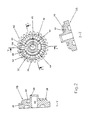
- the half pulley 10 illustrated in figure 1 comprises a flange 12, shaped on one side 14 so as, in cooperation with the other half pulley 16 illustrated in figure 2, to provide a "V"-shaped groove 18 in the finished product, as illustrated in figure 3.
- a central cylindrical bore 20 is provided in the flange, together with locating features in the form of a pin 22 and a pair of part-cylindrical bosses 24.
- the side 14 of the flange 12 which forms one half of the "V"-shaped groove includes twelve symmetric, triangular teeth 26.
- the teeth and the flange have central, relatively shallowly inclined surfaces 28, 30 and distal, relatively sharply inclined surfaces 32, 34. These help the teeth 26 and the groove 18 to grip the cord (not shown).
- the half pulley 16 illustrated in figure 2 also comprises a flange 36, shaped on one side 38 so as to cooperate with the other half pulley 10 illustrated in figure 1.
- a central bearing surface in the form of a cylindrical bore 40 is provided in the flange, continuing into a central boss 58, together with locating features in the form of a recess 42 and a pair of part-cylindrical detents 44.
- the side 38 of the flange 36 which forms one half of the "V"-shaped groove includes twelve symmetric, triangular teeth 46.
- the teeth and the flange have central, relatively shallowly inclined surfaces 48, 50 and distal, relatively sharply inclined surfaces 52, 54.
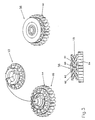
- the assembly of the pulley 56 is shown in figure 3.
- the central boss 58 will be received in the bore 20; the pin 22 will go into the recess 42; and the bosses 24 will go into the detents 44.
- the teeth 26 will line up exactly with the teeth 46, to provide a series of nips 60, separated by spaces 62.
- the finished pulley has an integral gear 64, moulded integrally with the second half 16.
- the two halves may be ultrasonically welded together, although care must be taken to prevent distortion, or may be glued together. In either case, the amount of pressure applied will vary the separation between the teeth 26, 46, which may be significant.
- the choice of material for the pulley and the choice of material for the cord are important. A balance must be struck between the need for good grip between the pulley and the cord and a desire to reduce abrasion of the cord.
- the presently preferred material for the pulley is DuPont's Minlon 23B1, a 37% mineral-glass-reinforced PA (nylon) 66 (28% mineral, 9% glass). This combines well with a 2.5 mm nominal diameter smooth braided polyester cord with polyester filler, such as are well known to those skilled in the art of blind making.
- An important advantage of the present invention can be appreciated from its ability to use unmodified polyester cords.
- Most motorised blinds use a drive train which can be described as incorporating a "positive drive” member.
- This member may take the form of a ball chain or an apertured tape or a helical drive shaft.
- the present invention takes advantage of unmodified cords, which it is able to do by virtue of its unique non-tensioned and self-threading construction. It is therefore applicable to the conversion of manual blinds to motorised form, not so much as an after-market accessory, but rather as a convenient way for manufacturers to modify their own products. This carries with it substantial development cost advantages, as there is not need to modify the perfectly good mechanism of a manual blind to accommodate any modified motorised drive train.
- FIG 4 illustrates a doctor 66.
- the doctor 66 includes a blade 68 which goes between the two parts 10, 16 of the pulley 56 to guide the cord out of the groove 18. It also includes a pair of wings 70, the purpose of which will become apparent.
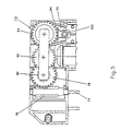
- Figure 5 shows an assembled gearbox 72.
- a spindle 74 is driven by a motor (not shown).
- Attached to the spindle 74 is a worm 76, which drives a helical gear 78.
- the helical gear then transmits drive via a reduction gear 80 and an idle gear 82 to the gear 64 on the pulley 56.
- Closely surrounding over one half of the circumference of the pulley 56 is a shoe 84, the two free ends of which run parallel and close to the edges of the wings 70 of the doctor 66.
- the doctor blade 68 is located in the "V"-shaped groove of the pulley 56.
- the wings 70 of the doctor 66 define, in conjunction with the gearbox housing and the shoe 84, an insertion aperture for the cord on each side of the pulley 56. Installing the cord onto the pulley is simplicity itself. The free end of the cord is offered up to the insertion aperture (under the appropriate wing 70) and the spindle 74 is rotated. The free end of the cord will then be trapped by a nip 60 in the pulley and between the pulley 56 and the shoe 84 and will begin to wind onto the pulley 56. If the cord does not come free of the pulley once it reaches the other side of the doctor 66, the doctor blade 68 will strip it out of the groove 18. In this sense, the mechanism can be described as self-threading.
- the use of the pulley and shoe combination described obviates the need for "back-tensioning" of the cord.
- the dimensions of the groove and the distance between the pulley and the shoe can be optimised to provide a desired degree of resistance to rotation of the pulley or a desired maximum load rating.
- the first should be as low as possible so as not to overload the motor; the second should be reasonably high to prevent slippage of the cord in normal use.
- HEIGHT indicates the maximum and minimum thicknesses of the complete pulley (an indicator of groove width);
- TEST CURRENT is the current draw required to drive the gearbox alone;
- CORD CURRENT is the lowest current draw required to drive the gearbox and cord;
- SIP CURRENT is the current at which the cord slips in the groove, if held fast; and
- LOAD is the load in the cord at which the onset of slippage was seen.
Landscapes
- Engineering & Computer Science (AREA)
- Structural Engineering (AREA)
- Architecture (AREA)
- Civil Engineering (AREA)
- Blinds (AREA)
- Catching Or Destruction (AREA)
- Devices For Conveying Motion By Means Of Endless Flexible Members (AREA)
- Operating, Guiding And Securing Of Roll- Type Closing Members (AREA)
- Rolls And Other Rotary Bodies (AREA)
- Pulleys (AREA)
Claims (29)
- Mécanisme d'entraínement d'un cordon pour un store comprenant une poulie (56) d'entraínement d'un cordon présentant une gorge circonférentielle tournée radialement vers l'extérieur, un sabot (84) par rapport auquel la poulie (56) tourne, entourant au moins une partie de la gorge circonférentielle dans la poulie (56), caractérisé en ce qu'une pluralité de points de contact (60) sont distribués autour de la gorge (18), les points de contact (60) étant définis par des éléments (26), (46) sur les deux côtés de la gorge, les éléments (26), (46) définissant chaque point de contact (60) étant opposés et alignés l'un sur l'autre sur chaque côté de la gorge de sorte qu'un cordon peut être entraíné en faisant tourner la poulie.
- Mécanisme selon la revendication 1 dans lequel le sabot (84) entoure au moins une moitié de la circonférence de la poulie (56).
- Mécanisme selon la revendication 1 ou 2 dans lequel chacun des points de contact est radial à l'intérieur de la gorge.
- Mécanisme selon l'une quelconque des revendications 1 à 3 dans lequel les points de contact (60) sont espacés de manière équidistante autour de la gorge circonférentielle (18).
- Mécanisme selon l'une quelconque des revendications 1 à 4 dans lequel les points de contact (60) sont au nombre d'au moins quatre.
- Mécanisme selon la revendication 5 dans lequel les points de contact (60) sont au nombre de douze.
- Mécanisme selon l'une quelconque des revendications précédentes dans lequel les éléments (26), (46) sont des dents triangulaires.
- Mécanisme selon la revendication 7 dans lequel les dents présentent des surfaces centrales (28, 30, 48, 50) inclinées de manière relativement peu prononcée, et des surfaces distales (32, 34, 52, 54) inclinées de manière relativement aiguë.
- Mécanisme selon l'une quelconque des revendications précédentes dans lequel les éléments (26), (46) sont symétriques.
- Mécanisme selon l'une quelconque des revendications précédentes dans lequel le mécanisme est adapté pour un auto-vissage par l'agencement d'un espace défini par la gorge circonférentielle et par le sabot dans lequel un cordon peut être inséré.
- Mécanisme selon l'une quelconque des revendications précédentes comprenant en outre un racloir (66) disposé adjacent à la gorge circonférentielle (18) dans la poulie (56) et adapté pour guider le cordon à l'extérieur de la gorge (18) quand la poulie (56) est mise en rotation.
- Mécanisme selon la revendication 11 dans lequel le racloir est sensiblement symétrique.
- Mécanisme selon la revendication 11 ou 12 dans lequel le racloir (66) définit une ouverture d'insertion pour le cordon .
- Mécanisme selon l'une quelconque des revendications précédentes comportant un cordon, dans lequel le cordon est retenu dans la gorge (18) par contact avec le sabot (84).
- Mécanisme selon la revendication 14, dans lequel les dimensions de la gorge (18) et/ou l'espacement entre la gorge (18) et le sabot (84) et/ou la taille du cordon est / sont sélectionnés pour fournir une résistance désirée à la rotation de la poulie (56) et/ou une charge maximum désirée qui peut être exercée sur le cordon.
- Store comportant un mécanisme d'entraínement de cordon selon l'une quelconque des revendications 1 à 15, comprenant en outre un cordon qui passe autour de la poulie (56) dans l'espace défini par la gorge circonférentielle (18) et le sabot (84).
- Store selon la revendication 16 dans lequel la poulie (56) est adaptée pour entraíner le cordon et le cordon est, à son tour, adapté pour actionner des parties mobiles du store.
- Store selon la revendication 16 ou 17 dans lequel le cordon n'est pas tendu en arrière en utilisation normale.
- Store selon l'une quelconque des revendications 16 à 18 dans lequel le cordon est retenu dans la gorge (18) par contact avec le sabot (84).
- Store selon la revendication 19 dans lequel les dimensions de la gorge (18) et/ou l'espacement entre la gorge (18) et le sabot (84) et/ou la taille du cordon est/sont sélectionnés pour fournir une résistance désirée à la rotation de la poulie (56) et/ou une charge maximum désirée qui peut être exercée sur le cordon.
- Procédé pour installer un mécanisme d'entraínement de cordon selon l'une quelconque des revendications 1 à 15 ou dans un store selon l'une quelconque des revendications 16 à 20, le procédé comprenant les étapes de :offrir une extrémité libre du cordon à l'espace défini par la gorge circonférentielle (18) et par le sabot (84), etmettre en rotation la poulie (56) pour entraíner la corde.
- Procédé selon la revendication 21 dans lequel le mécanisme inclut un racloir (66) disposé adjacent à la gorge circonférentielle (18) dans la poulie (56) et adapté pour guider le cordon hors de la gorge (18) quand la poulie (56) est mise en rotation, la méthode comprenant de plus la récupération de l'extrémité libre du cordon dès qu'elle a passé autour de la poulie (56) et est libérée par le racloir (66).
- Procédé selon la revendication 22 dans lequel le racloir (66) définit une ouverture d'insertion pour le cordon et l'extrémité libre du cordon est offerte vers le haut jusqu'à cette ouverture.
- Procédé selon l'une quelconque des revendications 21 à 23 dans lequel une pluralité de points de contact (60) sont distribués autour de la gorge circonférentielle (18) et l'extrémité libre du cordon est offerte vers le haut jusqu'à la région de la gorge (18) entre deux des points de contact (60).
- Combinaison d'une poulie et d'un sabot coopérant avec celle-ci pour un mécanisme d'entraínement de cordon selon l'une quelconque des revendications 1 à 15 ou pour un store selon l'une quelconque des revendications 16 à 20, la poulie comprenant une gorge circonférentielle (18), radialement tournée vers l'extérieur, le sabot entourant au moins une partie de la gorge, la poulie étant rotative par rapport au sabot, et une pluralité de points de contact (60) sont distribués autour de la gorge (18), les points de contact (60) étant définis par des éléments (26, 46) sur les deux côtés de la gorge et dans laquelle les éléments (26, 46) définissant chaque point de contact (60) sont opposés et alignés l'un avec l'autre sur chaque côté de la gorge.
- Combinaison selon la revendication 25 dans laquelle les points de contact de la poulie sont radiaux.
- Combinaison selon la revendication 25 ou 26 dans laquelle les éléments de la poulie sont des dents triangulaires.
- Combinaison selon la revendication 27 dans laquelle les éléments ont des surfaces centrales (28, 30, 48, 50) inclinées de manière relativement peu prononcée et des surfaces distales (32, 34, 52, 54) inclinées de manière relativement aiguë.
- Combinaison selon la revendication 25, 26 ou 27 dans laquelle les éléments de la poulie (26, 46) sont symétriques.
Applications Claiming Priority (3)
| Application Number | Priority Date | Filing Date | Title |
|---|---|---|---|
| GB9604861 | 1996-03-07 | ||
| GB9604861A GB2316969B (en) | 1996-03-07 | 1996-03-07 | Powered blinds |
| PCT/GB1997/000626 WO1997033064A1 (fr) | 1996-03-07 | 1997-03-07 | Mecanisme d'entrainement d'un cordon de store |
Publications (2)
| Publication Number | Publication Date |
|---|---|
| EP0885342A1 EP0885342A1 (fr) | 1998-12-23 |
| EP0885342B1 true EP0885342B1 (fr) | 2003-06-11 |
Family
ID=10790013
Family Applications (1)
| Application Number | Title | Priority Date | Filing Date |
|---|---|---|---|
| EP97906268A Expired - Lifetime EP0885342B1 (fr) | 1996-03-07 | 1997-03-07 | Mecanisme d'entrainement d'un cordon de store |
Country Status (7)
| Country | Link |
|---|---|
| US (1) | US6253822B1 (fr) |
| EP (1) | EP0885342B1 (fr) |
| AT (1) | ATE242838T1 (fr) |
| AU (1) | AU2101197A (fr) |
| DE (1) | DE69722776T2 (fr) |
| GB (1) | GB2316969B (fr) |
| WO (1) | WO1997033064A1 (fr) |
Families Citing this family (3)
| Publication number | Priority date | Publication date | Assignee | Title |
|---|---|---|---|---|
| KR100522357B1 (ko) * | 2003-09-26 | 2005-11-09 | 주식회사 윈스피아 | 내장형 전동 블라인드 장치 |
| US7389806B2 (en) * | 2005-02-24 | 2008-06-24 | Lawrence Kates | Motorized window shade system |
| US20090308543A1 (en) * | 2008-06-13 | 2009-12-17 | Lawrence Kates | Motorized window shade system and mount |
Family Cites Families (14)
| Publication number | Priority date | Publication date | Assignee | Title |
|---|---|---|---|---|
| US3630264A (en) * | 1969-11-24 | 1971-12-28 | Levolor Lorentzen Inc | Venetian blind tilting apparatus |
| SE377360B (fr) * | 1972-06-28 | 1975-06-30 | Perma System Ab | |
| GB1459053A (en) * | 1974-12-12 | 1976-12-22 | Nakamura I | Roller blind assembly |
| US4227423A (en) | 1978-04-21 | 1980-10-14 | Crowe Robert E | Line gripping pulley for a line hauler |
| US4413981A (en) * | 1981-06-12 | 1983-11-08 | White Eugene F | Sheave |
| US4418739A (en) * | 1982-01-15 | 1983-12-06 | Appropriate Technology Corporation | Insulating window covering |
| US4834164A (en) * | 1982-11-22 | 1989-05-30 | Lynmour, Ltd. | Window shade roller brackets and assembly including the same |
| GB2157753B (en) * | 1984-04-16 | 1987-07-01 | Hunter Douglas Ind Bv | A vertical blind headrail end cap |
| DE3423230C1 (de) * | 1984-06-21 | 1986-01-09 | Witold 1000 Berlin Felgendreher | Seilzug |
| GB8517721D0 (en) * | 1985-07-13 | 1985-08-21 | Harrison Of Birmingham Ltd | Pulling device |
| GB8521112D0 (en) * | 1985-08-23 | 1985-10-02 | Sandall R E | Circular cord-locking device |
| US5137073A (en) * | 1991-02-19 | 1992-08-11 | Teh Yor Industrial Co., Ltd. | Chain pulling device |
| DE4301527C2 (de) | 1993-01-21 | 1994-11-24 | Nippon Biso Kk | Seilzugvorrichtung |
| US5361822A (en) * | 1994-01-04 | 1994-11-08 | Nysan Shading Systems Ltd. | Shade operator |
-
1996
- 1996-03-07 GB GB9604861A patent/GB2316969B/en not_active Expired - Lifetime
-
1997
- 1997-03-07 WO PCT/GB1997/000626 patent/WO1997033064A1/fr not_active Ceased
- 1997-03-07 AU AU21011/97A patent/AU2101197A/en not_active Abandoned
- 1997-03-07 AT AT97906268T patent/ATE242838T1/de not_active IP Right Cessation
- 1997-03-07 DE DE69722776T patent/DE69722776T2/de not_active Expired - Lifetime
- 1997-03-07 EP EP97906268A patent/EP0885342B1/fr not_active Expired - Lifetime
- 1997-03-07 US US09/142,324 patent/US6253822B1/en not_active Expired - Lifetime
Also Published As
| Publication number | Publication date |
|---|---|
| GB9604861D0 (en) | 1996-05-08 |
| ATE242838T1 (de) | 2003-06-15 |
| DE69722776T2 (de) | 2004-05-13 |
| US6253822B1 (en) | 2001-07-03 |
| AU2101197A (en) | 1997-09-22 |
| DE69722776D1 (de) | 2003-07-17 |
| WO1997033064A1 (fr) | 1997-09-12 |
| EP0885342A1 (fr) | 1998-12-23 |
| GB2316969B (en) | 2000-01-26 |
| GB2316969A (en) | 1998-03-11 |
Similar Documents
| Publication | Publication Date | Title |
|---|---|---|
| US6158494A (en) | Winding device for window covering | |
| EP0885342B1 (fr) | Mecanisme d'entrainement d'un cordon de store | |
| KR19980087023A (ko) | 수동 체인 블록 | |
| CA2235170A1 (fr) | Appareil pour assembler, en forme d'helice, au moins deux filaments | |
| US6286294B1 (en) | Wire stranding machine | |
| US4015415A (en) | Twisting machine | |
| US6561335B2 (en) | Rotary clutch assembly having interlocking hubs | |
| DE3390227C2 (fr) | ||
| EP3324041B1 (fr) | Pale de rotor | |
| KR101194863B1 (ko) | 주낙 연승 장치 | |
| CN215974351U (zh) | 一种通轴式绕线机 | |
| DE1277083B (de) | Stillsetzvorrichtung fuer Einspindel-Kurzbandantriebe | |
| CN114833885A (zh) | 聚乙烯薄膜加工的分切装置及分切方法 | |
| JP4580094B2 (ja) | 撚線機 | |
| JP2717396B2 (ja) | 撚り線機のフライヤーバウ | |
| EP0150187B1 (fr) | Ameliorations en matiere de treuils | |
| JP2818744B2 (ja) | コード式草刈り機のコード長調整装置 | |
| JP2818770B2 (ja) | 飾り糸の撚り加工方法及び装置 | |
| KR200272261Y1 (ko) | 적재물 고정용 와이어 권취기 | |
| CN118954200B (zh) | 电缆收卷装置 | |
| US20260114437A1 (en) | Fishing reel | |
| JP3054763B2 (ja) | ペア撚線の撚りピッチ精度向上装置 | |
| KR200182475Y1 (ko) | 슬리터의 테이프 권취로울러구조 | |
| KR100566914B1 (ko) | 승강기의 와이어 권취장치 | |
| JP3802365B2 (ja) | ウインドレギュレータ |
Legal Events
| Date | Code | Title | Description |
|---|---|---|---|
| PUAI | Public reference made under article 153(3) epc to a published international application that has entered the european phase |
Free format text: ORIGINAL CODE: 0009012 |
|
| 17P | Request for examination filed |
Effective date: 19980925 |
|
| AK | Designated contracting states |
Kind code of ref document: A1 Designated state(s): AT CH DE FR IT LI NL |
|
| 17Q | First examination report despatched |
Effective date: 19990113 |
|
| RAP1 | Party data changed (applicant data changed or rights of an application transferred) |
Owner name: ECLIPSE BLIND SYSTEMS LIMITED |
|
| RBV | Designated contracting states (corrected) |
Designated state(s): AT CH DE FR IT LI NL |
|
| GRAG | Despatch of communication of intention to grant |
Free format text: ORIGINAL CODE: EPIDOS AGRA |
|
| GRAG | Despatch of communication of intention to grant |
Free format text: ORIGINAL CODE: EPIDOS AGRA |
|
| GRAH | Despatch of communication of intention to grant a patent |
Free format text: ORIGINAL CODE: EPIDOS IGRA |
|
| GRAH | Despatch of communication of intention to grant a patent |
Free format text: ORIGINAL CODE: EPIDOS IGRA |
|
| GRAA | (expected) grant |
Free format text: ORIGINAL CODE: 0009210 |
|
| RAP1 | Party data changed (applicant data changed or rights of an application transferred) |
Owner name: TURNILS (UK) LIMITED |
|
| AK | Designated contracting states |
Designated state(s): AT CH DE FR IT LI NL |
|
| PG25 | Lapsed in a contracting state [announced via postgrant information from national office to epo] |
Ref country code: LI Free format text: LAPSE BECAUSE OF FAILURE TO SUBMIT A TRANSLATION OF THE DESCRIPTION OR TO PAY THE FEE WITHIN THE PRESCRIBED TIME-LIMIT Effective date: 20030611 Ref country code: CH Free format text: LAPSE BECAUSE OF FAILURE TO SUBMIT A TRANSLATION OF THE DESCRIPTION OR TO PAY THE FEE WITHIN THE PRESCRIBED TIME-LIMIT Effective date: 20030611 Ref country code: AT Free format text: LAPSE BECAUSE OF FAILURE TO SUBMIT A TRANSLATION OF THE DESCRIPTION OR TO PAY THE FEE WITHIN THE PRESCRIBED TIME-LIMIT Effective date: 20030611 |
|
| REG | Reference to a national code |
Ref country code: CH Ref legal event code: EP |
|
| REF | Corresponds to: |
Ref document number: 69722776 Country of ref document: DE Date of ref document: 20030717 Kind code of ref document: P |
|
| REG | Reference to a national code |
Ref country code: CH Ref legal event code: PL |
|
| ET | Fr: translation filed | ||
| PLBE | No opposition filed within time limit |
Free format text: ORIGINAL CODE: 0009261 |
|
| STAA | Information on the status of an ep patent application or granted ep patent |
Free format text: STATUS: NO OPPOSITION FILED WITHIN TIME LIMIT |
|
| 26N | No opposition filed |
Effective date: 20040312 |
|
| PGFP | Annual fee paid to national office [announced via postgrant information from national office to epo] |
Ref country code: FR Payment date: 20050308 Year of fee payment: 9 |
|
| PGFP | Annual fee paid to national office [announced via postgrant information from national office to epo] |
Ref country code: IT Payment date: 20060331 Year of fee payment: 10 |
|
| REG | Reference to a national code |
Ref country code: FR Ref legal event code: ST Effective date: 20061130 |
|
| PG25 | Lapsed in a contracting state [announced via postgrant information from national office to epo] |
Ref country code: FR Free format text: LAPSE BECAUSE OF NON-PAYMENT OF DUE FEES Effective date: 20060331 |
|
| PG25 | Lapsed in a contracting state [announced via postgrant information from national office to epo] |
Ref country code: IT Free format text: LAPSE BECAUSE OF NON-PAYMENT OF DUE FEES Effective date: 20070307 |
|
| PGFP | Annual fee paid to national office [announced via postgrant information from national office to epo] |
Ref country code: DE Payment date: 20130227 Year of fee payment: 17 |
|
| PGFP | Annual fee paid to national office [announced via postgrant information from national office to epo] |
Ref country code: NL Payment date: 20130309 Year of fee payment: 17 |
|
| REG | Reference to a national code |
Ref country code: DE Ref legal event code: R119 Ref document number: 69722776 Country of ref document: DE |
|
| REG | Reference to a national code |
Ref country code: NL Ref legal event code: V1 Effective date: 20141001 |
|
| REG | Reference to a national code |
Ref country code: DE Ref legal event code: R119 Ref document number: 69722776 Country of ref document: DE Effective date: 20141001 |
|
| PG25 | Lapsed in a contracting state [announced via postgrant information from national office to epo] |
Ref country code: DE Free format text: LAPSE BECAUSE OF NON-PAYMENT OF DUE FEES Effective date: 20141001 |
|
| PG25 | Lapsed in a contracting state [announced via postgrant information from national office to epo] |
Ref country code: NL Free format text: LAPSE BECAUSE OF NON-PAYMENT OF DUE FEES Effective date: 20141001 |