EP0885559B1 - Véhicule pour la distribution et le mélange de fourrage - Google Patents
Véhicule pour la distribution et le mélange de fourrage Download PDFInfo
- Publication number
- EP0885559B1 EP0885559B1 EP98111175A EP98111175A EP0885559B1 EP 0885559 B1 EP0885559 B1 EP 0885559B1 EP 98111175 A EP98111175 A EP 98111175A EP 98111175 A EP98111175 A EP 98111175A EP 0885559 B1 EP0885559 B1 EP 0885559B1
- Authority
- EP
- European Patent Office
- Prior art keywords
- mixing
- wagon
- distributing
- floor
- shaft
- Prior art date
- Legal status (The legal status is an assumption and is not a legal conclusion. Google has not performed a legal analysis and makes no representation as to the accuracy of the status listed.)
- Expired - Lifetime
Links
- 239000004033 plastic Substances 0.000 claims description 9
- 239000002184 metal Substances 0.000 claims description 8
- 238000013459 approach Methods 0.000 claims description 4
- 230000007704 transition Effects 0.000 claims description 3
- 239000002023 wood Substances 0.000 claims description 3
- 239000011248 coating agent Substances 0.000 claims 1
- 238000000576 coating method Methods 0.000 claims 1
- 230000008878 coupling Effects 0.000 claims 1
- 238000010168 coupling process Methods 0.000 claims 1
- 238000005859 coupling reaction Methods 0.000 claims 1
- 238000006073 displacement reaction Methods 0.000 claims 1
- 230000001404 mediated effect Effects 0.000 claims 1
- 238000010008 shearing Methods 0.000 claims 1
- 239000000969 carrier Substances 0.000 description 11
- 238000010276 construction Methods 0.000 description 6
- 239000000835 fiber Substances 0.000 description 5
- 230000000694 effects Effects 0.000 description 4
- 238000000034 method Methods 0.000 description 4
- 239000004460 silage Substances 0.000 description 3
- 239000004459 forage Substances 0.000 description 2
- 230000005484 gravity Effects 0.000 description 2
- 239000002689 soil Substances 0.000 description 2
- 239000000853 adhesive Substances 0.000 description 1
- 230000001070 adhesive effect Effects 0.000 description 1
- 230000001174 ascending effect Effects 0.000 description 1
- 238000005452 bending Methods 0.000 description 1
- 238000005253 cladding Methods 0.000 description 1
- 230000002349 favourable effect Effects 0.000 description 1
- 239000002657 fibrous material Substances 0.000 description 1
- 239000004461 grass silage Substances 0.000 description 1
- 238000010422 painting Methods 0.000 description 1
- 238000009304 pastoral farming Methods 0.000 description 1
- 230000001737 promoting effect Effects 0.000 description 1
- 230000003014 reinforcing effect Effects 0.000 description 1
- 239000007787 solid Substances 0.000 description 1
Images


Classifications
-
- A—HUMAN NECESSITIES
- A01—AGRICULTURE; FORESTRY; ANIMAL HUSBANDRY; HUNTING; TRAPPING; FISHING
- A01K—ANIMAL HUSBANDRY; AVICULTURE; APICULTURE; PISCICULTURE; FISHING; REARING OR BREEDING ANIMALS, NOT OTHERWISE PROVIDED FOR; NEW BREEDS OF ANIMALS
- A01K5/00—Feeding devices for stock or game ; Feeding wagons; Feeding stacks
- A01K5/001—Fodder distributors with mixer or shredder
- A01K5/002—Fodder distributors with mixer or shredder with mixing or shredding element rotating on horizontal axis
-
- B—PERFORMING OPERATIONS; TRANSPORTING
- B01—PHYSICAL OR CHEMICAL PROCESSES OR APPARATUS IN GENERAL
- B01F—MIXING, e.g. DISSOLVING, EMULSIFYING OR DISPERSING
- B01F27/00—Mixers with rotary stirring devices in fixed receptacles; Kneaders
- B01F27/60—Mixers with rotary stirring devices in fixed receptacles; Kneaders with stirrers rotating about a horizontal or inclined axis
-
- B—PERFORMING OPERATIONS; TRANSPORTING
- B01—PHYSICAL OR CHEMICAL PROCESSES OR APPARATUS IN GENERAL
- B01F—MIXING, e.g. DISSOLVING, EMULSIFYING OR DISPERSING
- B01F33/00—Other mixers; Mixing plants; Combinations of mixers
- B01F33/50—Movable or transportable mixing devices or plants
- B01F33/502—Vehicle-mounted mixing devices
- B01F33/5023—Vehicle-mounted mixing devices the vehicle being a trailer which is hand moved or coupled to self-propelling vehicles
-
- B—PERFORMING OPERATIONS; TRANSPORTING
- B01—PHYSICAL OR CHEMICAL PROCESSES OR APPARATUS IN GENERAL
- B01F—MIXING, e.g. DISSOLVING, EMULSIFYING OR DISPERSING
- B01F2101/00—Mixing characterised by the nature of the mixed materials or by the application field
- B01F2101/06—Mixing of food ingredients
- B01F2101/18—Mixing animal food ingredients
-
- B—PERFORMING OPERATIONS; TRANSPORTING
- B01—PHYSICAL OR CHEMICAL PROCESSES OR APPARATUS IN GENERAL
- B01F—MIXING, e.g. DISSOLVING, EMULSIFYING OR DISPERSING
- B01F33/00—Other mixers; Mixing plants; Combinations of mixers
- B01F33/50—Movable or transportable mixing devices or plants
- B01F33/502—Vehicle-mounted mixing devices
Definitions
- the present invention relates to a mixing and distribution wagon for feed, according to the preamble of the claim 1.
- a carriage is known from DE 295 11 311 U.
- Such cars have been in practical operation known for a long time. They are primarily used for transportation of feed, for example green or dry feed or Silage, and can also be used to extend, i.e. also to distribute of such feed. If in addition to the known mixing and distribution car Industrial truck, such as a wheel loader, is also by adding mixing components one after the other some mixing in the box-shaped Construction possible, but for this large drive powers and therefore very strong drives or towing vehicles are necessary.
- the embodiment according to claim 3 ensures that in feed moving the wagon as it moves up has no storage space in the area of the fold; much more becomes the ascending through the cladding sheets Lining is drained inwards and then falls under Gravity back into the interior of the body.
- the measure specified in claim 4 ensures that the mixing shaft with its at least one mixing blade the feed supplied by means of the conveyor line already detected before this on the mixed shaft carrying End wall can jam. This will drive the power requirement for the rotation of the mixing shaft on Minimum reduced without that with the mixing shaft and their at least one mixing blade achievable mixing effect is reduced.
- the conveyor line Chain conveyor with a chain is between or on its Link several, spaced or transverse Drivers pointing outwards to the conveying direction are arranged, the top of the chain covering the floor for the most part.
- the chain is according to claim 8 preferably guided in slide rails.
- the slide rails can, for example, according to claim 9 as a C-profile made of plastic or wood or with plastic or wooden support.
- This cover guides the feed simply by gravity sideways where the feed returns to the mixing motion of the conveyor line is included.
- the cover due to its roof shape when loading for example a relatively solid silage block making sure that it hits the cover when it hits it breaks into at least two parts, each for itself are easier to shred than one complete silage block would be the case.
- the free end of the mixing shaft is advantageously sufficient up to the area above the neighboring feed wheel, whereby the outer mixing blade is viewed in the direction of the mixing shaft rotates above the conveyor wheel adjacent to the mixing shaft. This ensures that the feed flow in its entire cross-section in the sphere of activity the mixing blade arrives.
- the length of the mixing blades from the free end of the mixing shaft increases towards this supporting end wall.
- the mixing blades are crescent-shaped and tapered are, the curvature in the direction of rotation of the mixing shaft has. In this way, the mixing blades grip like a shovel into the feed and lift it off the ground towards the top, without causing the forage to compress and thus a strong braking of the mixing blades can come.
- the transition from the floor to the one supporting the mixing shaft Front wall at least in the effective area of the mixing blades beveled or rounded.
- the mixing shaft via a chain drive from another, approximately horizontal Shaft rotatable approximately in the longitudinal central axis the bottom of the box-shaped structure below the conveyor wheels runs, with the further wave on her one end via an angular gear with one of the conveyors is coupled and at its other end either carries a clutch with a PTO of a towing vehicle, especially tractor, is connectable or directly with the car's own drive unit connected is.
- This is not a separate drive for the two grants, i.e. the conveyor line and the Mixing shaft of the mixing and distribution wagon required.
- the branching of the initiated torque over a known as such chain drive and about one as well Known angular gear represents a structurally simple and robust solution.
- the two end walls expediently each have one semicircular plan and runs the closable Opening in the bottom approximately parallel in a semicircle to one end wall, the opening through a shape-adjustable slide lockable and infinitely variable can be released. Due to the location and shape of the opening a practically complete and easy to dose The body is emptied when the chain conveyor moves and given the mixing blade. When transporting feed in the box-shaped structure, the opening is closed; the drive of the chain conveyor and the mixing shaft can then be switched off or - for mixing during the trip - already switched on.
- an axis is included two wheels are present under the floor between the two conveyor wheels near the one, preferably the the feed wheel facing away from the drawbar is arranged. hereby becomes a particularly simple and therefore inexpensive Construction with favorable load distribution on axles and Drawbar reached.
- the box-shaped structure of the mixing and invention Distribution trolley is used above in many applications can remain open for most of its length, thereby loading is advantageously simplified. It is but advantageous, at least in the area above the Mixing shaft with the mixing blades a removable cover to be thrown out when mixing to avoid of feed.
- the tensioning device preferably at least one mechanical or pneumatic or. has hydraulic spring and preferably protected is located under the floor.
- the squeegees are a wearing part, these are preferably made of metal or plastic and are conveniently interchangeably attached to the floor.
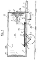
- FIG 1 is a mixing and distribution cart shown a box-shaped structure 12th with a flat bottom 1 with round ends.
- the height of the floor 1 protrudes to the right in FIG Drawbar 4 for connection to a towing vehicle.
- the box-shaped structure 12 on the floor 1 is on the drawbar side End by a semicircular in plan view curved end wall 7 and opposite at the other end limited by an identical, mirror-symmetrical end wall 7 '.
- the two end walls 7, 7 ' are through two longitudinal walls 120 connected, in the embodiment shown the front longitudinal wall is omitted to the To allow a look inside the structure 12.
- two wheels 3 are arranged, the are rotatably mounted on an axis 2 on the underside the bottom 1 is attached.
- a conveyor line 99 On the top of the bottom 1 is a conveyor line 99 arranged in the form of a chain conveyor consisting of a Chain 9 exists and moves in the direction of arrow 9 '.
- This Chain conveyor is an endless chain conveyor and runs around two spaced conveyor wheels 5 'and 5, the Rotation axes 6 'and 6 run perpendicular to the floor 1.
- the chain conveyor 9 has drivers, which will be used later of Figure 2 will be explained.
- the drawbar wheel 5 is via an angular gear 16, which is arranged in the area under the floor 1 is connected to a horizontal shaft 15 which thence to the free end of the drawbar 4.
- the shaft 15 carries a clutch, not shown Connection to a PTO of a towing vehicle.
- the shaft 15 carries a sprocket (not shown), that via a chain drive 14 to one above arranged, stored in the end wall 7 and about horizontal mixing shaft 8 leads in the direction of the arrow 8 'is rotatable, the chain drive 14 outside the drawbar-side end wall 7 is arranged.
- Mixing shaft 8 carries several regularly spaced apart Mixing paddle 10 perpendicular to the mixing shaft 8 stand out.
- the ends of the mixing blades 10 are at the front pointed like a prong.
- Opening 20 is arranged in the bottom 1 of the box-shaped structure 12. Below the opening 20 by a conformal Slider can be released and locked continuously is a tapered, funnel-like approach 17 available. A cross conveyor belt runs beneath this 17 'for the lateral discharge of the feed.
- the box-shaped structure 12 is smooth on the inside and on top provided with a reinforced edge 19.
- a removable Cover 11 e.g. a grid or mesh, arranged to prevent ejection of feed through the mixing blades 10.
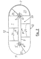
- Figure 2 shows a top view of the bottom 1, with all parts are omitted, which impair the overview, especially the shaft 8 with the wings 10.
- the two feed wheels 5 and 5 ' are also shown, around which the chain 9 of the chain conveyor in Arrow direction 9 'rotates when the drive over the shaft 15 is switched on.
- the drivers are on the chain 9 21 attached at regular intervals so that they can rotate around the conveyor wheels 5, 5 'and at the same time protrude as far as possible.
- the drivers 21 can be formed from angle or U profiles his.
- the length of the driver 21 and the outer contour of the bottom 1 are dimensioned so that the driver 21 at their Movement practically the entire area of the floor 1 sweep.
- Figure 3 of the drawing shows a second mixing and distribution car in cross section through its structure 12, wherein here an undercarriage existing under the structure 12 is not is shown.
- the structure 12 consists essentially from the flat floor 1, from its outer edge itself a sheet metal wall 120 extends upwards. At her top Edge 121 is the sheet metal wall 120 by triple folding towards the inside to a stable, but not towards the outside bulging stiffening edge.
- On top of the Structure 12 has a cover 11 that is at least over the front part of the structure 12, which is shown in Figure 3 is enough.
- the mixing shaft 8 On the semicircular one visible in the background front end wall 7 of the structure 12 is the mixing shaft 8 stored, which runs approximately horizontally and in the interior of the structure 12 protrudes. As Figure 3 illustrates, here is the mixing shaft 8 sideways to the right offset from the longitudinal center of the mixing and distribution wagon arranged. At the mixing shaft 8 are shown in the Embodiment three mixing blades 10 attached, the are each crescent-shaped and tapered. The three mixing blades 10 have different lengths, the length of the longest mixing blade 10 is chosen in this way is that its tip when the shaft 8 rotates in the direction of the rotation arrow 8 'just on the inner surfaces of the Construction 12 passes without touching it.
- the Mixing blades 10 are one behind the other on the mixing shaft 8 arranged with an axial distance, the shortest Mixing blades 10 furthest from the end wall 7 is arranged; the second longest mixing blade 10 follows afterwards and finally the longest mixing blade 10 is on next attached to the front wall 7.
- the mixing shaft 8 In the circumferential direction Looking at the mixing shaft 8 are the three mixing blades 10 arranged at a uniform distance of 120 °.
- Conveyor line 99 which is here also by a rotating Chain 9 is formed on the regular Distances running outward driver 21 attached are. Seen from above, the chain 9 runs against it Clockwise around, so that the driver 21 in the left half of the structure 12 towards the viewer and in the right half of the structure 12 away from the viewer move.
- cover 11 is also inclined Side surface trained to a jam of lining that is moved upwards by the mixing blades 10, safely excluded.
- Figure 4 of the drawing shows the front area of the floor 1 of the car from Figure 3 in a plan view, wherein the walls 120, the end wall 7 and the one mounted thereon Mixing shaft 8 with the mixing blades 10 not visible are.
- Driver 21 located at its inner end connected to the chain 9, for example welded are.
- Each driver 21 has one on its back Diagonal support 210, the foot end 211 loosely on the subsequent driver 21 at the foot end near the Chain 9 is supported.
- the diagonal supports 210 can do what not here visible, plastic pads are attached to the Reduce friction and wear.
- the roof-shaped from above Cover 91 visible in the area of the feed wheel 5 ends.
- the cover 91 is here with a slope 92 completed.
- the direction of the slope 92 is there chosen so that the tip 93 of the cover 91 on the Inlet side of the conveyor line 99, that is to say in FIG. 4 below, lies.
- FIG. 4 shows on the far right in the area of the semicircular end face of the bottom 1 the opening 20, which is used to eject the mixed feed down to one provided below, not shown here
- Cross conveyor belt is used.
- the opening 20 is by means of a flat slider attached below the floor 1 lockable and more or less as required fully releasable, the slider here too is not shown.
- the slide is in the longitudinal direction of the bottom 1 movable, which is preferably a hydraulic piston-cylinder arrangement is used.
- Figure 4 shows two squeegees 101, 102, which are mounted on the floor 1.
- the first Scraper strip 101 runs straight from chain 9 starting in the direction of movement 9 'of the conveyor line 99 viewed obliquely outwards in order to to strip adhesive feed outwards from the drivers 21.
- the squeegee serves the same purpose 102 in the area of the bottom 1 between the feed wheel 5 and the inner boundary 201 of the opening 20 and is curved.
- the inner boundary 201 of the opening 20 executed so that it is viewed in the direction of movement 9 ' steadily closer to the outer boundary 202 of the Opening 20 approaches.
- the inner boundary 201 of the opening 20 thus acts as a scraper or shear edge for from feed brought to the carriers 21 when the opening 20 is released and the feed is thrown down shall be.
- the mixing and Distribution car only at its opposite end or at both ends with a closable opening be provided.
Landscapes
- Life Sciences & Earth Sciences (AREA)
- Chemical & Material Sciences (AREA)
- Chemical Kinetics & Catalysis (AREA)
- Environmental Sciences (AREA)
- Birds (AREA)
- Animal Husbandry (AREA)
- Biodiversity & Conservation Biology (AREA)
- Mixers Of The Rotary Stirring Type (AREA)
- Housing For Livestock And Birds (AREA)
- Processing And Handling Of Plastics And Other Materials For Molding In General (AREA)
- Compositions Of Oxide Ceramics (AREA)
Claims (31)
- Véhicule de distribution et de mélange de fourrage avec une construction (12) en forme de caisse à fond (1) plan, avec un châssis (4) sur roues (3) et avec soit une barre d'attelage permettant la connexion amovible avec un véhicule tracteur, en particulier un tracteur agricole, ou sa propre unité motrice, étant donné que sur la partie supérieure du fond (1) est agencée, parallèlement à cette dernière, une ligne de transport (99) qui circule autour de deux roues de manutention (5, 5') écartées l'une de l'autre dans le sens longitudinal avec des axes de rotation (6, 6'), étant donné qu'au moins une des roues de manutention (5, 5') peut être entraínée par moteur vireur et étant donné qu'un arbre mélangeur (8) par exemple horizontal et pouvant être entraíné par moteur vireur portant au moins une aile de mélange (10) est raccordé et, qu'un orifice (20) se trouve au dessous de l'arbre mélangeur (8) dans le fond (1),
caractérisé par le fait que les axes de rotation (6, 6') des roues de manutention (5, 5') sont orientés perpendiculairement au fond et, que l'arbre mélangeur (8) est logée sur l'une des parois de bout (7, 7') de la construction (12) en forme de caisse et, que l'aile de mélange (10) est portée par une partie de l'arbre mélangeur (8) faisant saillie dans la construction et, que l'orifice (20) peut être fermé. - Véhicule de distribution et de mélange conformément à la revendication 1, caractérisé par le fait que la construction (12) comporte des parois en tôle (120) qui sont pliées sur leur bord supérieur (121) au moins aux parties droites de la paroi une ou plusieurs fois vers l'intérieur de la construction.
- Véhicule de distribution et de mélange conformément à la revendication 2, caractérisé par le fait que, sur le côté intérieur du bord supérieur des parois de tôle (120), des tôles de revêtement (122) inclinées se trouvent au moins au niveau des parois de bout de la construction entre le bord intérieur du (des) pli(s) et la surface intérieure de la paroi.
- Véhicule de distribution et de mélange conformément à l'une des revendications précédentes, caractérisé par le fait que l'arbre mélangeur (8) fait saillie du centre transversal de la paroi de bout (7), décalé sur le côté, dans un sens opposé au sens de transport (9') de la ligne de transport (99).
- Véhicule de distribution et de mélange conformément à l'une des revendications précédentes, caractérisé par le fait que la ligne de transport (99) est un convoyeur à chaíne comportant une chaíne (9) entre ou sur les maillons desquels sont agencés, transversalement ou obliquement par rapport au sens de transport (9'), plusieurs tocs d'entraínement (21) écartés l'un de l'autre et orientés vers l'extérieur, lesquels tocs d'entraínement balaient la plus grande portion de la partie supérieure du fond (1) lors de la circulation de la chaíne (9).
- Véhicule de distribution et de mélange conformément à la revendication 5, caractérisé par le fait que, à l'arrière de chaque toc d'entraínement (21), est installé un appui diagonal (210) dont l'extrémité de pied (211) est au moins appuyée de manière lâche au point de connexion situé entre la chaíne (9) et le toc d'entraínement (21) suivant aux niveaux de la ligne de transport se trouvant entre les roues de manutention (5, 5').
- Véhicule de distribution et de mélange conformément à la revendication 5 ou 6, caractérisé par le fait que les tocs d'entraínement (21) et, le cas échéant, les appuis diagonaux (210) correspondants, comportent sur leur côté inférieur un revêtement glissant échangeable en matière plastique.
- Véhicule de distribution et de mélange conformément à l'une des revendications 5 à 7, caractérisé par le fait que la chaíne (9) défile entre les roues de manutention (5, 5') dans une glissière (90) ouverte vers les tocs d'entraínement (21).
- Véhicule de distribution et de mélange conformément à la revendication 8, caractérisé par le fait que la glissière (90) est un profilé en C en matière plastique ou en bois ou bien un profilé en C revêtu de matière plastique ou de bois.
- Véhicule de distribution et de mélange conformément à l'une des revendications 5 à 9, caractérisé par le fait que la section se déplaçant vers l'avant et la section se déplaçant vers l'arrière de la chaíne (9) défilent parallèlement l'une par rapport à l'autre le long du centre du fond (1) et, que l'écartement entre ces dernières est au maximum égal à ¼ de la largeur du fond (1).
- Véhicule de distribution et de mélange conformément à la revendication 10, caractérisé par le fait qu'une chape (91) commune en forme de toit en coupe transversale se trouve au-dessus des deux sections de la chaíne (9).
- Véhicule de distribution et de mélange conformément à la revendication 11, caractérisé par le fait que la chape (91) comporte à chacune de ses extrémités se trouvant à proximité ou au-dessus des roues de manutention (5, 5') une fermeture (92) biseautée, étant donné que la pointe (93) du biseau repose sur le côté alimentation de la ligne de transport (99).
- Véhicule de distribution et de mélange conformément à l'une des revendications précédentes, caractérisé par le fait que sur la partie de l'arbre mélangeur (8) faisant saillie dans la construction (12) sont agencées à des intervalles réguliers plusieurs ailes de mélange (10) perpendiculaires à l'arbre mélangeur (8), lesquelles ailes se déplacent le long du fond (1), à proximité de cette dernière, lors de la rotation de l'arbre mélangeur (8).
- Véhicule de distribution et de mélange conformément à la revendication 13, caractérisé par le fait que l'extrémité libre de l'arbre mélangeur (8) fait saillie jusque dans la zone proche de la roue de manutention (5) voisine et, que, vu dans le sens de l'arbre mélangeur, l'aile de mélange (10) extérieure circule au-dessus de la roue de manutention (5).
- Véhicule de distribution et de mélange conformément à la revendication 13 ou 14, caractérisé par le fait qu'au moins trois ailes de mélange (10) de longueurs différentes disposées à des intervalles réguliers sont prévus dans le sens circonférentiel de l'arbre mélangeur (8).
- Véhicule de distribution et de mélange conformément à l'une des revendications 13 à 15, caractérisé par le fait que la longueur des ailes de mélange (10) de l'extrémité libre de l'arbre mélangeur (8) jusqu'à la paroi de bout (7) portant ce dernier s'accroít.
- Véhicule de distribution et de mélange conformément à l'une des revendications 13 à 16, caractérisé par le fait que les ailes de mélange (10) sont courbées en forme de croissant et biseautées, la courbure étant orientée dans le sens de rotation (8') de l'arbre mélangeur (8).
- Véhicule de distribution et de mélange conformément à l'une des revendications 13 à 17, caractérisé par le fait que la zone de transition du fond (1) à la paroi de bout (7) portant l'arbre mélangeur (8) est au moins inclinée ou arrondie dans la zone d'action des ailes de mélange (10).
- Véhicule de distribution et de mélange conformément à l'une des revendications 13 à 18, caractérisé par le fait que le mouvement de la ligne de transport (99) et la rotation de l'arbre mélangeur (8) se font dans un rapport tel que l'arbre mélangeur (8) effectue un tour complet ou plusieurs tours lorsque la ligne de transport (99) d'un intervalle entre deux tocs d'entraínement.
- Véhicule de distribution et de mélange conformément à l'une des revendications précédentes, caractérisé par le fait que l'arbre mélangeur (8) est mue par l'intermédiaire d'une commande par chaíne d'un autre arbre (15) par exemple horizontal qui se déplace par exemple dans la ligne médiane longitudinale du fond (1) de la construction (12) en forme de caisse au-dessous des roues de manutention (5, 5'), étant donné que l'autre arbre (15) est couplé à l'une de ses extrémités par l'intermédiaire d'un engrenage conique (16) à l'une des roues de manutention (5, 5') et, à l'autre extrémité, soit porte un accouplement pouvant être branché à une prise de force d'un véhicule tracteur, en particulier un tracteur agricole, soit est directement relié à l'unité d'entraínement du véhicule lui-même.
- Véhicule de distribution et de mélange conformément à l'une des revendications précédentes, caractérisé par le fait que les deux parois de bout (7, 7') ont chacune une projection horizontale en forme de demi-cercle, que l'orifice fermant (20) du fond (1) est parallèle, à peu près en forme de demi-cercle, à la paroi de bout (7) et, que l'orifice (20) peut être fermé par un coulisseau de forme adaptée et ouverte progressivement.
- Véhicule de distribution et de mélange conformément à la revendication 21, caractérisé par le fait que la limite (201) côté opposé à la paroi de l'orifice (20), vue dans le sens de mouvement (9') de la ligne de transport (99), est toujours plus proche de la limite (202) côté paroi de l'orifice (20).
- Véhicule de distribution et de mélange conformément à l'une des revendications précédentes, caractérisé par le fait qu'il existe un axe (2) avec deux roues (3) situé sous le fond (1) entre les deux roues de manutention (5, 5'), à proximité de la roue de manutention (5').
- Véhicule de distribution et de mélange conformément à l'une des revendications précédentes, caractérisé par le fait que la construction (12) en forme de caisse comporte sur sa partie supérieure au moins au-dessus de l'arbre (8) une chape (11) amovible.
- Véhicule de distribution et de mélange conformément à l'une des revendications précédentes, caractérisé par le fait que la chaíne (9) peut être précontrainte dans le sens longitudinal du véhicule de distribution et de mélange par un dispositif tendeur, étant donné que le dispositif tendeur comporte au moins un ressort mécanique ou pneumatique ou hydraulique.
- Véhicule de distribution et de mélange conformément à l'une des revendications 5 à 25, caractérisé par le fait que chacun des tocs d'entraínement (21) comporte un profilé dont la section est angulaire ou en U et/ou porte à ses extrémités des racleurs flexibles élastiques de préférence en caoutchouc.
- Véhicule de distribution et de mélange conformément à l'une des revendications 5 à 26, caractérisé par le fait que plusieurs barrettes racleuses (101, 102) sont agencées sur le fond (1) afin de garantir le raclage avec les tocs d'entraínement (21) et/ou que l'orifice (20) est constitué comme arête de coupe côté intérieur sur ses bords.
- Véhicule de distribution et de mélange conformément à la revendication 27, caractérisé par le fait que les barrettes racleuses (101, 102), vues dans le sens de mouvement (9') de la ligne de transport (99) depuis la chaíne (9), sont inclinées vers l'extérieur.
- Véhicule de distribution et de mélange conformément à la revendication 27 ou 28, caractérisé par le fait que, au niveau du fond (1), côté intérieur de l'orifice (20), est prévue au moins une barrette racleuse (102) courbée dont le mouvement est tangentiel à la limite (201) côté opposé à la paroi de l'orifice (20).
- Véhicule de distribution et de mélange conformément à la revendication 27 ou 28, caractérisé par le fait que les barrettes racleuses (101, 102) montées sur le fond (1) sont en métal ou en matière plastique et sont échangeables.
- Véhicule de distribution et de mélange conformément à la revendication 27 ou 28, caractérisé par le fait que, en plus de ou à la place de l'orifice (20) fermant prévu sous l'arbre mélangeur (10) dans le fond (1) est prévu un orifice fermant à proximité de la paroi de bout (7'), située au côté opposé de l'arbre mélangeur, de la construction (12).
Applications Claiming Priority (4)
| Application Number | Priority Date | Filing Date | Title |
|---|---|---|---|
| DE19725888 | 1997-06-19 | ||
| DE19725888A DE19725888A1 (de) | 1997-06-19 | 1997-06-19 | Misch- und Verteilwagen für Futter |
| DE19806656 | 1998-02-18 | ||
| DE19806656A DE19806656A1 (de) | 1997-06-19 | 1998-02-18 | Misch- und Verteilwagen für Futter |
Publications (3)
| Publication Number | Publication Date |
|---|---|
| EP0885559A2 EP0885559A2 (fr) | 1998-12-23 |
| EP0885559A3 EP0885559A3 (fr) | 2000-06-21 |
| EP0885559B1 true EP0885559B1 (fr) | 2003-02-12 |
Family
ID=26037562
Family Applications (1)
| Application Number | Title | Priority Date | Filing Date |
|---|---|---|---|
| EP98111175A Expired - Lifetime EP0885559B1 (fr) | 1997-06-19 | 1998-06-18 | Véhicule pour la distribution et le mélange de fourrage |
Country Status (3)
| Country | Link |
|---|---|
| EP (1) | EP0885559B1 (fr) |
| AT (1) | ATE232355T1 (fr) |
| DE (2) | DE19806656A1 (fr) |
Families Citing this family (6)
| Publication number | Priority date | Publication date | Assignee | Title |
|---|---|---|---|---|
| DE19830381A1 (de) | 1998-07-08 | 2000-01-20 | Von Der Heide Maschinenbau Gmb | Kettenförderer |
| DE202009004733U1 (de) * | 2009-04-24 | 2009-06-25 | Eckart, Gerhard | Vorrichtung zum Mischen von Schüttgut |
| DE202010016420U1 (de) * | 2010-12-09 | 2011-05-05 | B. Strautmann & Söhne GmbH u. Co. KG | Mischbehälter für die Aufnahme von Viehfutter |
| RU2583702C1 (ru) * | 2015-06-01 | 2016-05-10 | Федеральное государственное бюджетное научное учреждение Всероссийский научно-исследовательский институт механизации животноводства, ФГБНУ ВНИИМЖ | Мобильный кормораздатчик |
| CN107494293A (zh) * | 2017-08-23 | 2017-12-22 | 益福光(天津)电子科技有限公司 | 一种高端智能机器人 |
| CN115428741B (zh) * | 2022-09-26 | 2023-10-27 | 佳木斯大学 | 一种无死角利清刷的三转位猪食槽槽形及其型线设计方法 |
Family Cites Families (4)
| Publication number | Priority date | Publication date | Assignee | Title |
|---|---|---|---|---|
| IT209372Z2 (it) * | 1986-10-30 | 1988-10-05 | Caravaggi Gian Lorenzo | Macchina per sminuzzare balle di paglia, fieno e simili. |
| FR2678695B3 (fr) * | 1991-07-03 | 1993-10-15 | Crms | Dispositif d'entrainement selectif d'un arbre de sortie au moyen d'un arbre moteur et machine pour distribuer les fourrages, qui en est equipee. |
| DE29511311U1 (de) * | 1995-07-13 | 1995-09-14 | B. Strautmann & Söhne GmbH u. Co, 49196 Bad Laer | Futterverteilwagen |
| EP0754405A1 (fr) * | 1995-07-21 | 1997-01-22 | Tiziano Faccia | Dispositif amélioré de déchiquetage et mixage des produits fibreux d'alimentation pour animaux |
-
1998
- 1998-02-18 DE DE19806656A patent/DE19806656A1/de not_active Withdrawn
- 1998-06-18 DE DE59807155T patent/DE59807155D1/de not_active Expired - Fee Related
- 1998-06-18 AT AT98111175T patent/ATE232355T1/de not_active IP Right Cessation
- 1998-06-18 EP EP98111175A patent/EP0885559B1/fr not_active Expired - Lifetime
Also Published As
| Publication number | Publication date |
|---|---|
| ATE232355T1 (de) | 2003-02-15 |
| DE19806656A1 (de) | 1999-08-19 |
| EP0885559A2 (fr) | 1998-12-23 |
| DE59807155D1 (de) | 2003-03-20 |
| EP0885559A3 (fr) | 2000-06-21 |
Similar Documents
| Publication | Publication Date | Title |
|---|---|---|
| EP2522545B1 (fr) | Espace de chargement pour véhicule, notamment d'un véhicule de transport, dispositif d'espace de chargement et un véhicule de transport | |
| EP0885559B1 (fr) | Véhicule pour la distribution et le mélange de fourrage | |
| EP0223004B1 (fr) | Machine mobile pour broyer et distribuer des balles d'ensilage | |
| DE3419997A1 (de) | Futtermischwagen | |
| DE2743739A1 (de) | Streumaschine, insbesondere stalldungstreuer | |
| EP0102406A1 (fr) | Chariot pour la réception et la distribution de silage, de paille et de produits similaires | |
| EP2397425B1 (fr) | Station de transbordement mobile pour le transbordement de matières en vrac | |
| DE2706803A1 (de) | Futterwagen | |
| EP2058172A1 (fr) | Structure d'espace de charge avec une paroi frontale mobile et véhicule de transport muni d'une telle structure | |
| DE1166700B (de) | Lastfahrzeug mit Schrappeinrichtung | |
| DE2426025A1 (de) | Vorrichtung zur entnahme von viehfutter aus einem silo | |
| DE3033533A1 (de) | Streuer fuer stalldung u.ae. massen | |
| DE2638963C2 (de) | Rübenerntemaschine | |
| DE19725888A1 (de) | Misch- und Verteilwagen für Futter | |
| DE1755729A1 (de) | Landwirtschaftlicher wagen | |
| DE3051007C2 (de) | Landwirtschaftliches Ladefahrzeug mit einer an seinem einen Ende angeordneten Dosiereinrichtung | |
| DE3800605A1 (de) | Anlage zum auf- und abbau von mischbetthalden | |
| DE20304321U1 (de) | Mischgerät | |
| DE886875C (de) | Entlade- und Foerdereinrichtung fuer Ackerwagen | |
| DE3023653C2 (de) | Landwirtschaftliches Ladefahrzeug mit einer an seinem einen Ende angeordneten Dosiereinrichtung | |
| EP0654299A1 (fr) | Dispositif de mélange et de distribution de nourriture de bétail | |
| DE1949848A1 (de) | Selbsttaetig entladendes Fahrzeug | |
| DE3543312A1 (de) | Entspeicherungsgeraet fuer schuettguthalden | |
| DE29900199U1 (de) | Vorrichtung zum Mischen und Verteilen von Schüttgütern | |
| DE1811095B2 (de) | Landwirtschaftlicher Wagen |
Legal Events
| Date | Code | Title | Description |
|---|---|---|---|
| PUAI | Public reference made under article 153(3) epc to a published international application that has entered the european phase |
Free format text: ORIGINAL CODE: 0009012 |
|
| AK | Designated contracting states |
Kind code of ref document: A2 Designated state(s): AT DE FR GB IE IT NL SE |
|
| AX | Request for extension of the european patent |
Free format text: AL;LT;LV;MK;RO;SI |
|
| PUAL | Search report despatched |
Free format text: ORIGINAL CODE: 0009013 |
|
| AK | Designated contracting states |
Kind code of ref document: A3 Designated state(s): AT BE CH CY DE DK ES FI FR GB GR IE IT LI LU MC NL PT SE |
|
| AX | Request for extension of the european patent |
Free format text: AL;LT;LV;MK;RO;SI |
|
| RIC1 | Information provided on ipc code assigned before grant |
Free format text: 7A 01K 5/00 A, 7A 01F 29/00 B |
|
| 17P | Request for examination filed |
Effective date: 20001220 |
|
| AKX | Designation fees paid |
Free format text: AT DE FR GB IE IT NL SE |
|
| GRAH | Despatch of communication of intention to grant a patent |
Free format text: ORIGINAL CODE: EPIDOS IGRA |
|
| GRAH | Despatch of communication of intention to grant a patent |
Free format text: ORIGINAL CODE: EPIDOS IGRA |
|
| GRAA | (expected) grant |
Free format text: ORIGINAL CODE: 0009210 |
|
| AK | Designated contracting states |
Designated state(s): AT DE FR GB IE IT NL SE |
|
| PG25 | Lapsed in a contracting state [announced via postgrant information from national office to epo] |
Ref country code: NL Free format text: LAPSE BECAUSE OF FAILURE TO SUBMIT A TRANSLATION OF THE DESCRIPTION OR TO PAY THE FEE WITHIN THE PRESCRIBED TIME-LIMIT Effective date: 20030212 Ref country code: IT Free format text: LAPSE BECAUSE OF FAILURE TO SUBMIT A TRANSLATION OF THE DESCRIPTION OR TO PAY THE FEE WITHIN THE PRESCRIBED TIME-LIMIT;WARNING: LAPSES OF ITALIAN PATENTS WITH EFFECTIVE DATE BEFORE 2007 MAY HAVE OCCURRED AT ANY TIME BEFORE 2007. THE CORRECT EFFECTIVE DATE MAY BE DIFFERENT FROM THE ONE RECORDED. Effective date: 20030212 Ref country code: IE Free format text: LAPSE BECAUSE OF FAILURE TO SUBMIT A TRANSLATION OF THE DESCRIPTION OR TO PAY THE FEE WITHIN THE PRESCRIBED TIME-LIMIT Effective date: 20030212 Ref country code: GB Free format text: LAPSE BECAUSE OF FAILURE TO SUBMIT A TRANSLATION OF THE DESCRIPTION OR TO PAY THE FEE WITHIN THE PRESCRIBED TIME-LIMIT Effective date: 20030212 Ref country code: FR Free format text: LAPSE BECAUSE OF FAILURE TO SUBMIT A TRANSLATION OF THE DESCRIPTION OR TO PAY THE FEE WITHIN THE PRESCRIBED TIME-LIMIT Effective date: 20030212 |
|
| REG | Reference to a national code |
Ref country code: GB Ref legal event code: FG4D Free format text: NOT ENGLISH |
|
| REF | Corresponds to: |
Ref document number: 59807155 Country of ref document: DE Date of ref document: 20030320 Kind code of ref document: P |
|
| PG25 | Lapsed in a contracting state [announced via postgrant information from national office to epo] |
Ref country code: SE Free format text: LAPSE BECAUSE OF FAILURE TO SUBMIT A TRANSLATION OF THE DESCRIPTION OR TO PAY THE FEE WITHIN THE PRESCRIBED TIME-LIMIT Effective date: 20030512 |
|
| PG25 | Lapsed in a contracting state [announced via postgrant information from national office to epo] |
Ref country code: AT Free format text: LAPSE BECAUSE OF NON-PAYMENT OF DUE FEES Effective date: 20030618 |
|
| NLV1 | Nl: lapsed or annulled due to failure to fulfill the requirements of art. 29p and 29m of the patents act | ||
| REG | Reference to a national code |
Ref country code: IE Ref legal event code: FG4D Free format text: GERMAN |
|
| GBV | Gb: ep patent (uk) treated as always having been void in accordance with gb section 77(7)/1977 [no translation filed] |
Effective date: 20030212 |
|
| REG | Reference to a national code |
Ref country code: IE Ref legal event code: FD4D Ref document number: 0885559E Country of ref document: IE |
|
| PLBE | No opposition filed within time limit |
Free format text: ORIGINAL CODE: 0009261 |
|
| STAA | Information on the status of an ep patent application or granted ep patent |
Free format text: STATUS: NO OPPOSITION FILED WITHIN TIME LIMIT |
|
| PG25 | Lapsed in a contracting state [announced via postgrant information from national office to epo] |
Ref country code: DE Free format text: LAPSE BECAUSE OF NON-PAYMENT OF DUE FEES Effective date: 20040101 |
|
| EN | Fr: translation not filed | ||
| 26N | No opposition filed |
Effective date: 20031113 |