EP0885589A1 - Méthode et système pour évaluer le système circulatoire d'un sujet vivant - Google Patents
Méthode et système pour évaluer le système circulatoire d'un sujet vivant Download PDFInfo
- Publication number
- EP0885589A1 EP0885589A1 EP97109869A EP97109869A EP0885589A1 EP 0885589 A1 EP0885589 A1 EP 0885589A1 EP 97109869 A EP97109869 A EP 97109869A EP 97109869 A EP97109869 A EP 97109869A EP 0885589 A1 EP0885589 A1 EP 0885589A1
- Authority
- EP
- European Patent Office
- Prior art keywords
- pressure
- subject
- pulse
- wave
- blood
- Prior art date
- Legal status (The legal status is an assumption and is not a legal conclusion. Google has not performed a legal analysis and makes no representation as to the accuracy of the status listed.)
- Withdrawn
Links
- 238000000034 method Methods 0.000 title description 10
- 230000036772 blood pressure Effects 0.000 claims abstract description 68
- 238000011156 evaluation Methods 0.000 claims abstract description 50
- 210000001367 artery Anatomy 0.000 claims abstract description 5
- 238000001514 detection method Methods 0.000 claims description 16
- 230000000737 periodic effect Effects 0.000 claims description 10
- 230000003247 decreasing effect Effects 0.000 claims description 2
- 230000003534 oscillatory effect Effects 0.000 description 68
- 238000005259 measurement Methods 0.000 description 17
- 210000000115 thoracic cavity Anatomy 0.000 description 12
- 210000002321 radial artery Anatomy 0.000 description 10
- 238000009530 blood pressure measurement Methods 0.000 description 8
- 230000003205 diastolic effect Effects 0.000 description 8
- 230000007423 decrease Effects 0.000 description 7
- 206010020772 Hypertension Diseases 0.000 description 6
- 230000001105 regulatory effect Effects 0.000 description 5
- 239000000523 sample Substances 0.000 description 5
- 210000000707 wrist Anatomy 0.000 description 5
- 230000008859 change Effects 0.000 description 4
- 229940079593 drug Drugs 0.000 description 4
- 239000003814 drug Substances 0.000 description 4
- 230000029058 respiratory gaseous exchange Effects 0.000 description 4
- 206010003210 Arteriosclerosis Diseases 0.000 description 3
- 208000011775 arteriosclerosis disease Diseases 0.000 description 3
- 238000007664 blowing Methods 0.000 description 3
- 238000010586 diagram Methods 0.000 description 3
- 235000005911 diet Nutrition 0.000 description 3
- 230000000378 dietary effect Effects 0.000 description 3
- 230000006870 function Effects 0.000 description 3
- 238000012886 linear function Methods 0.000 description 3
- 239000004065 semiconductor Substances 0.000 description 3
- 238000011282 treatment Methods 0.000 description 3
- 210000000709 aorta Anatomy 0.000 description 2
- 210000002302 brachial artery Anatomy 0.000 description 2
- 230000035487 diastolic blood pressure Effects 0.000 description 2
- 239000000284 extract Substances 0.000 description 2
- 230000006872 improvement Effects 0.000 description 2
- QSHDDOUJBYECFT-UHFFFAOYSA-N mercury Chemical compound [Hg] QSHDDOUJBYECFT-UHFFFAOYSA-N 0.000 description 2
- 229910052753 mercury Inorganic materials 0.000 description 2
- 210000004165 myocardium Anatomy 0.000 description 2
- 230000002093 peripheral effect Effects 0.000 description 2
- 230000003068 static effect Effects 0.000 description 2
- 230000035488 systolic blood pressure Effects 0.000 description 2
- 230000001276 controlling effect Effects 0.000 description 1
- 201000010099 disease Diseases 0.000 description 1
- 208000037265 diseases, disorders, signs and symptoms Diseases 0.000 description 1
- 230000000694 effects Effects 0.000 description 1
- 239000004744 fabric Substances 0.000 description 1
- 210000001105 femoral artery Anatomy 0.000 description 1
- 230000036541 health Effects 0.000 description 1
- 210000005240 left ventricle Anatomy 0.000 description 1
- 238000012986 modification Methods 0.000 description 1
- 230000004048 modification Effects 0.000 description 1
- 229910021421 monocrystalline silicon Inorganic materials 0.000 description 1
- 230000008569 process Effects 0.000 description 1
- 238000012545 processing Methods 0.000 description 1
- 230000001902 propagating effect Effects 0.000 description 1
- 230000010349 pulsation Effects 0.000 description 1
- 230000000630 rising effect Effects 0.000 description 1
- 230000001360 synchronised effect Effects 0.000 description 1
Images


Classifications
-
- A—HUMAN NECESSITIES
- A61—MEDICAL OR VETERINARY SCIENCE; HYGIENE
- A61B—DIAGNOSIS; SURGERY; IDENTIFICATION
- A61B5/00—Measuring for diagnostic purposes; Identification of persons
- A61B5/02—Detecting, measuring or recording for evaluating the cardiovascular system, e.g. pulse, heart rate, blood pressure or blood flow
- A61B5/021—Measuring pressure in heart or blood vessels
- A61B5/02108—Measuring pressure in heart or blood vessels from analysis of pulse wave characteristics
- A61B5/02125—Measuring pressure in heart or blood vessels from analysis of pulse wave characteristics of pulse wave propagation time
-
- A—HUMAN NECESSITIES
- A61—MEDICAL OR VETERINARY SCIENCE; HYGIENE
- A61B—DIAGNOSIS; SURGERY; IDENTIFICATION
- A61B5/00—Measuring for diagnostic purposes; Identification of persons
- A61B5/02—Detecting, measuring or recording for evaluating the cardiovascular system, e.g. pulse, heart rate, blood pressure or blood flow
- A61B5/021—Measuring pressure in heart or blood vessels
- A61B5/022—Measuring pressure in heart or blood vessels by applying pressure to close blood vessels, e.g. against the skin; Ophthalmodynamometers
-
- A—HUMAN NECESSITIES
- A61—MEDICAL OR VETERINARY SCIENCE; HYGIENE
- A61B—DIAGNOSIS; SURGERY; IDENTIFICATION
- A61B5/00—Measuring for diagnostic purposes; Identification of persons
- A61B5/02—Detecting, measuring or recording for evaluating the cardiovascular system, e.g. pulse, heart rate, blood pressure or blood flow
- A61B5/026—Measuring blood flow
- A61B5/0285—Measuring or recording phase velocity of blood waves
Definitions
- This invention relates to medical diagnostic devices. More specifically, this invention is directed to a system and method for evaluating the circulatory system of a living subject.
- Some circulatory ailments that cause high blood pressure such as arteriosclerosis, are discovered by measuring the subject's blood pressure with a blood pressure measurement apparatus.
- a blood pressure measurement apparatus is disclosed in Japanese Laid-Open Application No. 6-292660.
- the blood-pressure measurement device measures the blood pressure of a living subject using a cuff that is wrapped around a portion of the living subject.
- the cuff applies pressure to the living subject.
- the living subject's blood pressure is measured using a well-known oscillometric method, which is based on detecting changes in the amplitude of a synchronous wave pulsation as the pressure applied by the cuff is gradually released.
- a blood pressure measurement is effective in discovering the existence of high blood pressure in a living subject, it is not an effective method for evaluating improvement in the underlying cause of the living subject's high blood pressure brought about by dietary treatments.
- Blood pressure measurement is not effective in evaluating the effects of dietary treatment on the circulatory ailment because high-blood-pressure patients typically take blood-pressure-reducing medication.
- a blood pressure measurement will not reveal if the underlying condition causing the living subject's high blood pressure is improving.
- This invention provides a device that accurately evaluates a living subject's circulatory system, even if the living subject is taking high-blood-pressure medication.
- the device provides a time-difference determining device that determines a time difference between predetermined periodic points on a subject's electrocardiographic waveform and predetermined periodic points on corresponding oscillatory pressure-pulse waves of the living subject.
- a strain application device applies a physical strain to the subject's body for a predetermined period of time so that the subject's blood pressure changes.
- a blood-pressure measurement device measures the subject's blood pressure while the subject's blood pressure is changing.
- a circulatory-system evaluation device determines a relationship between changes in the subject' s blood pressure and corresponding time differences determined by the time-difference determining device. The circulatory-system evaluation device evaluates the subject's circulatory system based on the hysteresis present in the determined relationship.
- the inventors have discovered, as a result of extended study, that the relationship between changes in a subject's blood pressure and changes in the corresponding time differences between predetermined periodic points on the subject's electrocardiographic waveform and predetermined periodic points on corresponding oscillatory pressure-pulse waves of the living subject exhibits little or no hysteresis if the subject's circulatory system is healthy. Furthermore, the relationship exhibits hysteresis if the subject's circulatory system is not healthy.
- a propagation velocity determining device is used to determine the propagation velocities of a subject's oscillatory pressure-pulse waves based on the time difference determination by the time-difference determining device.
- the circulatory-system evaluation device determines a relationship between changes in the subject's blood pressure and changes in the propagation velocities of corresponding oscillatory pressure-pulse waves.
- the circulatory-system evaluation device evaluates the subject's circulatory system based on the hysteresis present in the determined relationship. The amount of hysteresis present is an indicator of the relative health of the subject's circulatory system.
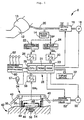
- Fig. 1 shows the circulatory-system evaluation device 8 of this invention.
- the device 8 comprises an inflatable cuff 10 which is preferably formed by a rubber bag that is positioned inside a flexible cloth bag.
- the inflatable cuff 10 is wrappable around a portion of a living subject, e.g., an upper arm 12 of a subject.
- the inflatable cuff 10 is connected via piping 20 to a pressure sensor 14, a switch valve 16 and a first air pump 18.
- the switch valve 16 is selectively placeable in either an inflation position, a slow-deflation position or a quick-deflation position.
- the switch valve 16 allows pressurized air from the first air pump 18 to be supplied to the inflatable cuff 10.
- the switch valve 16 allows the pressurized air in the inflatable cuff 10 to be slowly discharged.
- the switch valve 16 allows the pressurized air in the inflatable cuff 10 to be quickly discharged.
- the pressure sensor 14 detects an air pressure in the inflatable cuff 10 and supplies a pressure signal SP, representing the detected pressure, to a static-pressure discrimination circuit 22 and a pressure-pulse-wave discrimination circuit 24.
- the static-pressure discrimination circuit 22 includes a low-pass filter that extracts a static component contained in the pressure signal SP, i.e., a cuff pressure signal SK that represents the static cuff pressure.
- the cuff pressure signal SK is supplied to an electronic control device 28 via a first A/D converter 26.
- the pressure-pulse-wave discrimination circuit 24 includes a band-pass filter that extracts an oscillatory component of the pressure signal SP falling within a predetermined frequency range.
- the oscillatory component is supplied as a cuff pressure signal SM 1 to the electronic control device 28 via a second A/D converter 30.
- the cuff pressure signal SM 1 represents an oscillatory pressure wave that is produced from a brachial artery of the subject and that propagates to the area on the subject's right arm 12 in contact with the inflatable cuff 10.
- the electronic control device 28 preferably includes a central processing unit (CPU) 29, a read-only memory (ROM) 31, a random-access memory (RAM) 33 and an input-output (I/O) port (not shown).
- the CPU 29 processes input signals according to control programs pre-stored in the ROM 31 using the RAM 33 as temporary storage.
- the CPU 29 outputs display signals to a display device 32.
- the CPU 29 supplies a control signal to the switch valve 16 to place it in the inflation position and a drive signal to the first air pump 18 to inflate the inflatable cuff 10, thus compressing the upper portion of the subject's right arm 12.
- the CPU 29 then supplies a control signal to the switch valve 16 to place it in the slow-deflation position, thus gradually reducing the air pressure in the inflatable cuff 10.
- the CPU 29 obtains the cuff pressure signal SM 1 and the cuff pressure signal SK from the pressure sensor 14 via the pressure-pulse-wave discrimination circuit 24 and the static-pressure discrimination circuit 22, respectively.
- the CPU 29 determines the subject's systolic blood pressure value SBP, the subject's diastolic blood pressure value DBP and the subject's mean blood pressure value BP mean based on the obtained signals SM 1 and SK using well-known oscillometric blood pressure measuring techniques. These techniques are based on the variation of the amplitudes of the heartbeat-synchronous pulses of the oscillatory pressure-pulse wave (i.e., the cuff pressure pulse signal SM 1 ).
- the circulatory-system evaluation device 8 further includes a oscillatory pressure-pulse-wave detection probe 34.
- the oscillatory pressure-pulse-wave detection probe 34 has a container-like housing 36 that is detachably worn, using attachment bands 40, on a body surface 38 of a subject's wrist 42 downstream of an upper arm.
- the oscillatory pressure-pulse-wave detection probe 34 is preferably worn on the other than the arm 12 around which the inflatable cuff 10 is worn. However, the oscillatory pressure-pulse-wave detection probe 34 may also be worn downstream of the upper arm 12 around which the inflatable cuff 10 is worn.
- the oscillatory pressure-pulse-wave detection probe 34 is positioned on the subject's wrist 42 such that an opening of the housing 36 is opposed to the body surface 38.
- a pressure-pulse-wave sensor 46 is supported by the housing 36 via a diaphragm 44 such that the pressure-pulse-wave sensor 46 is movable relative to the housing 36 and is advanceable through the opening of the housing 36.
- the housing 36, the diaphragm 44 and the pressure-pulse-wave sensor 46 cooperate with one another to define a pressure chamber 48.
- Pressurized air is supplied to the pressure chamber 48 from a second air pump 50 via a pressure regulator valve 52.
- the pressure-pulse-wave sensor 46 is pressed against a radial artery 56 of the subject via the body surface or skin 38 with a pressing force P HD .
- the pressing force P HD corresponds to the air pressure in the pressure chamber 48.
- the pressure-pulse-wave sensor 46 includes a number of semiconductor pressure-sensing elements (not shown) which are arranged along a pressing surface 54 of a semiconductor chip.
- the semiconductor chip is suitably formed from monocrystalline silicon.
- the pressure-pulse-wave sensor 46 is pressed against the subject's radial artery 56 via the body surface 38 of the subject's wrist 42 to detect oscillatory pressure-pulse waves of the subject.
- the oscillatory pressure-pulse waves are produced by the subject's cardiac muscle and propagate along the radial artery 56. They are transmitted to the pressure-pulse-wave sensor 46 via the body surface 38.
- the pressure-pulse-wave sensor 46 generates an oscillatory pressure-pulse-wave signal SM 2 representing the detected oscillatory pressure-pulse wave.
- the oscillatory pressure-pulse-wave signal SM 2 is input to the electronic control device 28 via a third A/D converter 58.
- the pressure-pulse-wave sensor 46 detects an oscillatory pressure-pulse wave propagating through the subject's radial artery 56.
- the CPU 29 of the electronic control device 28 supplies drive signals to the second air pump 50 and control signals to the pressure regulator valve 52 to regulate the air pressure in the pressure chamber 48.
- the CPU 29 regulates the magnitude of the pressing force P HD applied by the pressure-pulse-wave sensor 46 to the subject's radial artery 56 via the body surface 38.
- the CPU 29 determines an optimum value for the pressing force P HD for the pressure-pulse-wave sensor 46 based on the respective magnitudes of heartbeat-synchronous pulses of the oscillatory pressure-pulse wave detected by the pressure-pulse-wave sensor 46 while the air pressure of the chamber 48 is changed.
- the CPU 29 then controls the pressure regulator valve 52 to maintain the optimum pressing force P HD .
- the circulatory-system evaluation device 8 also includes an electrocardiographic-waveform detection circuit 60.
- the electrocardiographic-waveform detection circuit 60 continuously detects an electrocardiographic waveform that indicates the change in electric potential of the subject's cardiac muscle.
- the electrocardiographic-waveform detection circuit 60 determines the electrocardiographic waveform from signals supplied by multiple electrodes 62.
- the electrodes 62 are placed at predetermined positions on the subject.
- the electrocardiographic-waveform detection circuit 60 is suitably an electrocardiograph, and the electrocardiographic waveform is suitably an electrocardiogram detected by the electrocardiograph.
- the electrocardiographic-waveform detection circuit 60 supplies the electrocardiographic waveform to the electronic control device 28.
- the display device 32 may optionally record the electrocardiographic waveform on a recording sheet (not shown).
- the circulatory-system evaluation device 8 also includes an indicator lamp 67.
- the indicator lamp 67 is used to signal the living subject being evaluated to begin a strain operation, as is described in more detail below.
- Fig. 2 shows a thoracic-cavity pressure applicator and measurement device 63.
- the pressure applicator and measurement device 63 includes a mouthpiece 66 that is connected to a pressure gauge 64 via a hollow rubber tube 65.
- the pressure gauge 64 is suitably a mercury pressure gauge.
- the CPU 29 illuminates an indicator lamp 67.
- the indicator lamp 67 is illuminated, the subject being evaluated executes the well-known Valsalva's operation.
- the subject bites down on, and blows into, the mouthpiece 66.
- the subject blows into the mouthpiece with a force sufficient to maintain a predetermined pressure reading on the pressure gauge 64 for a predetermined period of time.
- the subject being evaluated blows into the mouthpiece 66 with a force sufficient to maintain a pressure value of approximately 40 mmHg for a period of approximately 15 seconds.
- the subject removes the mouthpiece and resumes normal breathing.
- the pressure inside the subject's thoracic cavity is maintained at an elevated level, resulting in an increase in the subject's blood pressure from an initial level.
- the pressure inside the subject's thoracic cavity returns to normal levels and the subject's blood pressure decreases back to its initial level.
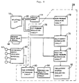
- Fig. 3 illustrates the control functions of a first preferred embodiment of the electronic control device 28 of the circulatory-system evaluation device 8.
- the electronic control device 28 regulates the air pressure in the inflatable cuff 10 via a cuff-pressure regulating circuit 79.
- the cuff-pressure regulating circuit 79 switches the switch valve 16 to the inflation position and drives the first air pump 18 to quickly increase the air pressure in the inflatable cuff 10 to a predetermined target value, e.g., 180 mmHg.
- the cuff-pressure regulating circuit 79 switches the switch valve 16 to a slow-deflation position to slowly decrease the air pressure in the inflatable cuff 10.
- a blood-pressure measuring circuit 72 uses a well-known oscillometric method to measure the subject's systolic blood pressure, diastolic blood pressure and mean blood pressure.
- the blood pressure measurement is based on the variation in the amplitudes of the heartbeat-synchronous pulses of the oscillatory pressure-pulse waves (i.e., of the cuff oscillatory pressure-pulse-wave signal SM 1 ) obtained through the pressure-pulse-wave discrimination circuit 24 while the air pressure in the inflatable cuff 10 slowly decreases.
- the pressure-pulse-wave sensor 46 is preferably pressed on the body surface 38 of the subject's wrist 42 on the subject's other arm from the arm 12 on which the inflatable cuff 10 is worn.
- the pressure-pulse-wave sensor 46 detects a oscillatory pressure-pulse wave produced from the radial artery 56 of the subject's wrist 42.
- a relationship determining circuit 76 determines a relationship between a monitor-blood-pressure value MBP and a oscillatory pressure-pulse-wave magnitude P M based on at least one blood pressure value measured by the blood-pressure measuring circuit 72 and at least one oscillatory pressure-pulse wave (i.e., of the oscillatory pressure-pulse-wave signal SM 2 ) detected by the pressure-pulse-wave sensor 46. This relationship is determined for each subject and each circulatory evaluation measurement.
- a monitor-blood-pressure determining circuit 78 successively determines, based on the relationship between the monitor-blood-pressure value MBP and the magnitude P M of the oscillatory pressure-pulse wave, a systolic monitorblood-pressure value MBP SYS and a diastolic monitor-bloodpressure value MBP DIA based on the magnitudes P M of each heartbeat-synchronous pulse of the oscillatory pressure-pulse waves (i.e., of the oscillatory pressure-pulse-wave signal SM 2 ) detected by the pressure-pulse-wave sensor 46.
- the maximum (upper-peak) magnitude P Mmax and minimum (lower-peak) magnitude P Mmin of each heartbeat-synchronous pulse is used to determine the systolic monitor-blood-pressure value MBP SYS and the diastolic monitor-blood-pressure value MBP DIA .
- the monitor-blood-pressure values determined by the monitor-blood-pressure determining circuit 78 are continuously output to the display device 32.
- the display device 32 successively displays the determined monitor-blood-pressure values for each heartbeat-synchronous pulse.
- a time-difference determining circuit 80 determines a time difference TD RP between a predetermined periodic point on the electrocardiographic waveform and a predetermined periodic point on a corresponding oscillatory pressure-pulse wave.
- the time-difference determining circuit 80 determines the time difference TD RP between an R point on the electrocardiographic waveform and a maximum point (upper-peak) of a pulse of a corresponding oscillatory pressure-pulse wave, as shown in Fig. 5.
- the time difference TD RP corresponds to the time it takes the oscillatory pressure-pulse wave to propagate from the aorta to the radial artery of the subject's arm.
- a circulatory-system evaluation circuit 82 illuminates the indicator lamp 67 to initiate the Valsalva's operation, in which the subject blows into the mouthpiece 66 of the thoracic-cavity pressure applicator and measurement device 63.
- the circulatory-system evaluation circuit 82 maintains the indicator lamp 67 in an illuminated state for a predetermined period of time, e.g., fifteen seconds. During this period of time, the subject continues to blow into the mouthpiece 66 with a force sufficient to maintain a predetermined pressure reading on the pressure gauge 64 of the pressure applicator and measurement device 63, e.g., 40 mmHg.
- the pressure indicated on the pressure gauge 64 corresponds to an internal pressure in the subject's thoracic cavity.
- the internal pressure generated in the subject's thoracic cavity causes a rise in the subject's blood pressure from an initial value.
- the circulatory-system evaluation circuit 82 turns off the indicator lamp 67. This signals the subject to remove the mouthpiece 66 and resume normal breathing. The resumption of normal breathing causes the subject's blood pressure to decrease back to its initial value.
- the monitor-blood-pressure determining circuit 78 determines the monitor-blood-pressure values MBP SYS and MBP DIA , and the time-difference determining circuit 80 determines corresponding time differences TD RP .
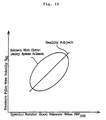
- the circulatory-system evaluation circuit 82 makes a curve of the relationship between changes in the monitor-bloodpressure values determined by the monitor-blood-pressure determining circuit 78, preferably the systolic monitor-blood-pressure values MBP SYS , and corresponding changes in the time differences TD RP determined by the time-difference determining circuit 80, as shown in Fig. 6.
- time difference TD RP and the systolic monitor-blood-pressure value MBP SYS change linearly as the subject's blood pressure changes for a healthy subject, as shown by the line labeled "Healthy Subject.”
- the time difference TD RP and the systolic monitor-blood-pressure value MBP SYS as the subject's blood pressure changes, varies over an elliptical path when the subject has a circulatory system ailment, such as, for example, arteriosclerosis.
- the graph of TD RP vs. MBP SYS for a subject with a circulatory system ailment exhibits hysteresis.
- the time difference values determined by the time-difference determining circuit 80 as the subject's systolic monitor-blood-pressure value increases differ from the time difference values determined while the subject's systolic monitor-blood-pressure value decreases.
- the graph of TD RP vs. MBP SYS does not exhibit hysteresis.
- the circulatory-system evaluation circuit 82 determines the area enclosed by the ellipse-shaped curve. The circulatory-system evaluation circuit 82 then determines the degree of the circulatory ailment in the subject, e.g., the degree of arteriosclerosis, by comparing the area of the ellipse-shaped curve to predetermined standardized values.
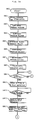
- Figs. 7A and 7B show a flowchart of a preferred control routine for the circulatory-system evaluation device 8 shown in Fig. 1 using the electronic control device of Fig. 3.
- the control routine starts at SA1 and proceeds to step SA2, where the control system controls the second air pump 50 and the pressure regulator valve 52 to vary the air pressure inside the pressure chamber 48.
- the control system gradually varies the pressure inside the pressure chamber 48 until the control system determines that the pressure inside the pressure chamber 48 maximizes the amplitude of the oscillatory pressure-pulse wave detected by the pressure-pulse-wave sensor 46.
- the pressure inside the chamber that maximizes the amplitude of the oscillatory pressure-pulse wave is the optimal pressure force P HD of the pressure-pulse-wave sensor 46.
- the control system then maintains this pressure during the course of the circulatory system evaluation measurement.
- step SA3 the control system increases the air pressure in the inflatable cuff 10 until a target pressure value is reached, e.g., 180 mmHg.
- the control system accomplishes this by switching the switch valve 16 to the inflation position and turning on the first air pump 18.
- the control system stops the first air pump 18.
- step SA4 the control system switches the switch valve 16 to the slow-deflation position. Accordingly, the air pressure in the inflatable cuff 10 gradually decreases, preferably at a rate of 3 mmHg/sec.
- step SA5 the blood-pressure measuring circuit 72 determines the subject's systolic, diastolic and mean blood pressure from the changes in the amplitudes in the cuff oscillatory pressure-pulse waves detected during the slow release of air from the inflatable cuff 10.
- the subject's blood pressure is determined using well-known oscillometric techniques.
- the blood-pressure measuring circuit 72 determines the subject's pulse rate from the time interval between the respective times of detection of two successive heartbeat-synchronous pulses of the cuff oscillatory pressure-pulse-wave signal. Control then continues to step SA6.
- step SA6 the control system switches the switch valve 16 to the quick-deflation position to rapidly release the remaining air in the inflatable cuff 10.
- step SA7 the relationship determining circuit 76 determines a relationship between the blood pressure values determined at step SA5 and the magnitudes P Mmax and P Mmin of the oscillatory pressure-pulse waves detected by pressure-pulse-wave sensor 46.
- step SA8 the control system illuminates the indicator lamp 67, which signals the subject to start the Valsalva's operation by blowing into the mouthpiece 66 of the thoracic-cavity pressure applicator and measurement device 63.
- step SA9 the control system determines whether the R point on the electrocardiographic waveform has been detected. If the R point on the electrocardiographic waveform is detected, control continues to step SA10. Otherwise, control jumps back to step SA9.
- step SA10 the control system reads in the time at which the R point of the electrocardiographic waveform was detected.
- step SA11 the control system determines if the maximum point of a corresponding oscillatory pressure-pulse wave detected by the pressure-pulse-wave sensor 46 has been detected. If the maximum point of the oscillatory pressure-pulse wave is detected, control continues to step SA12. Otherwise, control jumps back to step SA11.
- step SA12 the control system reads in the time at which the maximum point of the oscillatory pressure-pulse wave was detected.
- step SA13 the control system determines the oscillatory pressure-pulse wave upper-peak value P Mmax and the oscillatory pressure-pulse wave lower-peak value P Mmin . Control then continues to step SA14.
- step SA14 the monitor-blood-pressure determining circuit 78 determines the systolic monitor-blood-pressure value MBP SYS and the diastolic monitor-blood-pressure value MBP DIA from the upper-peak and lowerpeak values determined at step SA13 and the relationship determination made at step SA7.
- the control system then displays the determined monitor-blood-pressure values on the display device 32.
- step SA15 the time-difference determining circuit 80 determines the time difference TD RP between the R point of the electrocardiographic waveform and the maximum point of the corresponding oscillatory pressure-pulse wave. Control then continues to step SA16.
- step SA16 the control system plots the time difference TD RP determined at step SA15 corresponding to the systolic monitor-blood-pressure value MBP SYS determined at step SA14.
- the resulting graph curve is preferably a two-dimensional curve, as shown in Fig. 6, with the systolic monitor-blood-pressure value MBP SYS plotted along one axis and the time difference TD RP plotted along an orthogonal axis.
- step SA17 the control system determines if the indicator lamp 67 is still illuminated. If the indicator lamp 67 is illuminated, control continues to step SA18. Otherwise, control jumps to SA20.
- step SA18 the control system determines whether a predetermined time period has elapsed.
- the predetermined time period corresponds to a time period over which the Valsalva's operation is performed, e.g., fifteen seconds. If the predetermined time period has elapsed, control continues to step SA19. Otherwise, control returns to step SA9 and steps SA9-SA18 are repeated.
- step SA19 the control system turns off the indicator lamp 67.
- step SA20 the control system determines if an entire time difference versus systolic monitor blood pressure curve has been completed. In a preferred embodiment, the control system determines that the curve has been completed when it detects that a time difference/systolic monitor blood pressure data point has been repeated. If the entire curve has been completed, control continues to step SA21. Otherwise, control returns to SA9 and steps SA9-SA20 are repeated.
- step SA21 the circulatory-system evaluation circuit 82 determines the area enclosed by the time difference/systolic monitor blood pressure curve, as described above. The control system then displays the value of the area enclosed by the curve on the display device 32. Control then continues to step SA22, where the control routine stops.
- the circulatory-system evaluation device 8 of this invention evaluates the circulatory system of a subject based on the relationship between changes in the time difference TD RP and changes in the subject's systolic monitor blood pressure MBP SYS , it is possible to evaluate the improvement in a circulatory system disease brought about by dietary treatments and the like, even in subjects that are taking blood pressure reducing medication.
- the circulatory-system evaluation circuit 82 compares the area enclosed by the time difference/systolic monitor blood pressure curve to predetermined standardized values, a subject's circulatory system is quantitatively evaluated.
- a thoracic-cavity pressure applicator and measurement device 63 which assists the subject in maintaining a constant internal thoracic cavity pressure during the circulatory system evaluation measurement, improves the accuracy of the circulatory system evaluation.
- a common pressure-pulse-wave sensor 46 is used to determine the maximum point of the oscillatory pressure-pulse wave at step SA11 and the upper-peak and lower-peak values of the oscillatory pressure-pulse wave at step SA13, the cost of the circulatory-system evaluation device is reduced.
- Fig. 8 is a second embodiment of the electronic control device 28 of the circulatory-system evaluation device 8.
- the embodiment of Fig. 8 includes a propagation velocity determining circuit 84. Otherwise, the embodiment of Fig. 8 is identical to the embodiment shown in Fig. 3. Accordingly, common elements are labeled with the same element numbers.
- the propagation velocity determining circuit 84 determines a propagation rate V M (m/sec) of the oscillatory pressure-pulse wave.
- the oscillatory pressure-pulse wave propagates through an artery of the subject, including the radial artery of the subject's right arm 12.
- Fig. 9A and 9B show a flowchart of a preferred control routine for the circulatory-system evaluation device of Fig. 1 using the electronic control device 28 shown in Fig. 8.
- the routine starts at SB1 and proceeds to step SB2, where the control system controls the second air pump 50 and the pressure regulator valve 52 to vary the air pressure inside the pressure chamber 48.
- the control system gradually varies the pressure inside the pressure chamber 48 until the control system determines that the pressure inside the pressure chamber 48 maximizes the amplitude of the oscillatory pressure-pulse wave detected by the pressure-pulse-wave sensor 46.
- the pressure inside the chamber that maximises the amplitude of the oscillatory pressure-pulse wave is the optimal pressure force P HD of the pressure-pulse-wave sensor 46.
- the control system then maintains this pressure during the course of the circulatory system evaluation measurement.
- step SB3 the control system increases the air pressure in the inflatable cuff 10 until a target pressure value is reached, e.g., 180 mmHg.
- the control system accomplishes this by switching the switch valve 16 to the inflation position and turning on the first air pump 18.
- the control system stops the first air pump 18.
- step SB4 the control system switches the switch valve 16 to the slow-deflation position. Accordingly, the air pressure in the inflatable cuff 10 gradually decreases, preferably at a rate of 3 mmHg/sec.
- step SB5 the blood-pressure measuring circuit 72 determines the subject's systolic, diastolic and mean blood pressure from the changes in the amplitudes in the cuff oscillatory pressure-pulse waves detected during the slow release of air from the inflatable cuff 10.
- the subject's blood pressure is determined using well-known oscillometric techniques.
- the blood-pressure measuring circuit 72 determines the subject's pulse rate from the time interval between the respective times of detection of two successive heartbeat-synchronous pulses of the cuff oscillatory pressurepulse-wave signal. Control then continues to step SB6.
- step SB6 the control system switches the switch valve 16 to the quick-deflation position to rapidly release the remaining air in the inflatable cuff 10.
- step SB7 the relationship determining circuit 76 determines a relationship between the blood pressure values determined at SB5 and the magnitudes P Mmax and P Mmin of the oscillatory pressure-pulse waves detected by pressure-pulse-wave sensor 46.
- step SB8 the control system illuminates the indicator lamp 67, which signals the subject to start the Valsalva's operation by blowing into the mouthpiece 66 of the thoracic-cavity pressure applicator and measurement device 63.
- step SB9 the control system determines whether the R point on the electrocardiographic waveform has been detected. If the R point on the electrocardiographic waveform is detected, control continues to step SB10. Otherwise, control jumps back to step SB9.
- step SB10 the control system reads in the time at which the R point of the electrocardiographic waveform was detected.
- step SB11 the control system determines if the maximum point of a corresponding oscillatory pressure-pulse wave detected by the pressure-pulse-wave sensor 46 has been detected. If the maximum point of the oscillatory pressure-pulse wave is detected, control continues to step SB12. Otherwise, control jumps back to step SB11.
- step SB12 the control system reads in the time at which the maximum point of the oscillatory pressure-pulse wave was detected.
- step SB13 the control system determines the oscillatory pressure-pulse wave upper-peak value P Mmax and the oscillatory pressure-pulse wave lower-peak value P Mmin . Control then continues to step SB14.
- the monitor-blood-pressure determining circuit 78 determines the systolic monitor-blood-pressure value MBP SYS and the diastolic monitor-blood-pressure value MBP DIA from the upper-peak and lower-peak values determined at step SB13 and the relationship determination made at step SB7.
- the control system then displays the determined monitor-blood-pressure values on the display device 32.
- step SB15 the time-difference determining circuit 80 determines the time difference TD RP between the R point of the electrocardiographic waveform and the maximum point of the corresponding oscillatory pressure-pulse wave. Control then continues to step SA16.
- step SB16 the control system determines the propagation velocity V M1 of the oscillatory pressure-pulse wave based on the time difference TD RP determined at step SB15.
- step SB17 the control system plots the propagation velocity V M1 determined at step SB16 corresponding to the systolic monitor-blood-pressure value MBP SYS determined at step SB14.
- the resulting graph is preferably a two-dimensional curve, as shown in Fig. 10, with the systolic monitor-blood-pressure value MBP SYS plotted along one axis and the pressure-pulse wave propagation velocity V M1 plotted along an orthogonal axis.
- step SB18 the control system determines if the indicator lamp 67 is still illuminated. If the indicator lamp 67 is illuminated, control continues to step SB19. Otherwise, control jumps to SB21.
- step SB19 the control system determines whether a predetermined time period has elapsed.
- the predetermined time period corresponds to a time period over which the Valsalva's operation is performed, e.g., fifteen seconds. If the predetermined time period has elapsed, control continues to step SB20. Otherwise, control returns to step SB9 and steps SB9-SB19 are repeated.
- the control system turns off the indicator lamp 67. Then, at step SB21, the control system determines if an entire propagation velocity versus systolic monitor blood pressure curve has been completed. In a preferred embodiment, the control system determines that the curve has been completed when it detects that a propagation velocity/systolic monitor blood pressure data point has been repeated. If the entire curve has been completed, control continues to step SB22. Otherwise, control returns to SB9 and steps SB9-SB21 are repeated.
- step SB22 the circulatory-system evaluation circuit 82 determines the area enclosed by the propagation velocity/systolic monitor blood pressure curve, as described above. The control system then displays the value of the area enclosed by the curve on the display device 32. Control then continues to step SB22, where the control routine stops.
- the electronic control device 28 including the blood-pressure measuring circuit 72, the cuff regulating circuit 79, the relationship determining circuit 76, the monitor-blood-pressure determining circuit 78, the time-difference determining circuit 80 and the circulatory-system evaluation circuit 82, and optionally the propagation velocity determining circuit 84, is preferably implemented using a programmed general purpose computer.
- the electronic control device can also be implemented using a special purpose computer, a programmed microprocessor or microcontroller and peripheral integrated circuit elements, an ASIC or other integrated circuit, a hardwired electronic or logic circuit such as a discrete element circuit, a programmable logic device such as a FPGA, a PLD, a PLA or a PAL, or the like.
- any device on which a finite state machine capable of implementing the flowcharts shown in Figs. 7A and 7B or Figs. 9A and 9B and capable of controlling the peripheral devices shown in Figs. 3 and 8 can be implemented, can be used to implement the electronic control device 28 of this invention.
- the circulatory-system evaluation circuit 82 utilizes the time difference TD RP between the R point of the electrocardiographic waveform and the maximum point of the oscillatory pressure-pulse wave, it may also utilize a time difference TD QP between a Q point of the electrocardiographic waveform and a maximum point of the oscillatory pressure-pulse wave.
- the time difference may be defined from an S point of the electrocardiographic waveform to the maximum point of the oscillatory pressure-pulse wave.
- the time difference may be defined from an R point, a Q point or an S point to a minimum point of the oscillatory pressure-pulse wave.
- the areas enclosed by the time difference/systolic monitor-blood-pressure value curve and the propagation velocity/systolic monitor blood pressure curve are displayed as numerical values on the display device 32.
- the curves themselves may be graphically displayed on the display device 32 in addition to or instead of the numerical values of the areas.
- a mercury pressure gauge is preferably used for the pressure gauge 64 of the thoracic-cavity pressure applicator and measurement device 63, an aneroid or other type of pressure gauge may be used.
- control system signals a subject to begin the Valsalva's operation by illuminating the indicator lamp 67
- control system may also use other means to signal the subject. For example, the control system can sound a buzzer to signal the subject.
- the circulatory-system evaluation circuit 82 may also evaluate a subject's circulatory system by curveting the time difference TD RP or the propagation velocity V M1 as a function of the diastolic monitor-blood-pressure value MBP DIA .
- a Valsalva's operation to change the subject's blood pressure during the circulatory system evaluation measurement
- other means of changing the subject's blood pressure may be utilized.
- a treadmill may be used to change the subject's blood pressure by having the subject run on a treadmill for a predetermined period of time.
- the propagation velocity V M1 is determined based on the time difference TD RP between each pulse of the electrocardiographic waveform and a corresponding pulse of the oscillatory pressure-pulse wave.
- the propagation velocity may be determined based on a time difference between a heartbeat-synchronous pulse of a first oscillatory pressure-pulse wave detected by the pressure sensor 14 and a corresponding heartbeat-synchronous pulse of a second oscillatory pressure-pulse wave detected by the pressure-pulse-wave sensor 46.
- the propagation velocity V M1 of the oscillatory pressure-pulse wave may be measured by attaching a set of pressure-pulse-wave sensors to the carotid and the femoral arteries of the subject.
Landscapes
- Health & Medical Sciences (AREA)
- Life Sciences & Earth Sciences (AREA)
- Cardiology (AREA)
- Biomedical Technology (AREA)
- Medical Informatics (AREA)
- Physics & Mathematics (AREA)
- Vascular Medicine (AREA)
- Biophysics (AREA)
- Pathology (AREA)
- Engineering & Computer Science (AREA)
- Veterinary Medicine (AREA)
- Heart & Thoracic Surgery (AREA)
- Physiology (AREA)
- Molecular Biology (AREA)
- Surgery (AREA)
- Animal Behavior & Ethology (AREA)
- General Health & Medical Sciences (AREA)
- Public Health (AREA)
- Hematology (AREA)
- Ophthalmology & Optometry (AREA)
- Measuring Pulse, Heart Rate, Blood Pressure Or Blood Flow (AREA)
Priority Applications (3)
| Application Number | Priority Date | Filing Date | Title |
|---|---|---|---|
| JP33485995A JP3580925B2 (ja) | 1995-12-22 | 1995-12-22 | 生体の循環機能評価装置 |
| US08/867,814 US5921936A (en) | 1995-12-22 | 1997-06-03 | System and method for evaluating the circulatory system of a living subject |
| EP97109869A EP0885589A1 (fr) | 1995-12-22 | 1997-06-17 | Méthode et système pour évaluer le système circulatoire d'un sujet vivant |
Applications Claiming Priority (3)
| Application Number | Priority Date | Filing Date | Title |
|---|---|---|---|
| JP33485995A JP3580925B2 (ja) | 1995-12-22 | 1995-12-22 | 生体の循環機能評価装置 |
| US08/867,814 US5921936A (en) | 1995-12-22 | 1997-06-03 | System and method for evaluating the circulatory system of a living subject |
| EP97109869A EP0885589A1 (fr) | 1995-12-22 | 1997-06-17 | Méthode et système pour évaluer le système circulatoire d'un sujet vivant |
Publications (1)
| Publication Number | Publication Date |
|---|---|
| EP0885589A1 true EP0885589A1 (fr) | 1998-12-23 |
Family
ID=27238237
Family Applications (1)
| Application Number | Title | Priority Date | Filing Date |
|---|---|---|---|
| EP97109869A Withdrawn EP0885589A1 (fr) | 1995-12-22 | 1997-06-17 | Méthode et système pour évaluer le système circulatoire d'un sujet vivant |
Country Status (3)
| Country | Link |
|---|---|
| US (1) | US5921936A (fr) |
| EP (1) | EP0885589A1 (fr) |
| JP (1) | JP3580925B2 (fr) |
Cited By (5)
| Publication number | Priority date | Publication date | Assignee | Title |
|---|---|---|---|---|
| EP1095611A1 (fr) * | 1999-11-01 | 2001-05-02 | Colin Corporation | Dispositif d'obtention d'informations sur la propagation de la pulsation cardiaque |
| EP1243220A1 (fr) * | 2001-03-21 | 2002-09-25 | Colin Corporation | Appareil de contrôle en continu de la pression sanguine |
| EP1306048A1 (fr) * | 2001-10-24 | 2003-05-02 | Colin Corporation | Appareil pour évaluer le degré d'artériosclérose |
| EP1175864A3 (fr) * | 2000-07-26 | 2004-01-02 | Colin Corporation | Appareil d'évaluation de la condition post opératoire |
| CN103099610A (zh) * | 2011-11-11 | 2013-05-15 | 杭州电子科技大学 | 基于左右肱动脉脉搏波传输时间差的动态血压测量装置及方法 |
Families Citing this family (51)
| Publication number | Priority date | Publication date | Assignee | Title |
|---|---|---|---|---|
| DE19746377C1 (de) * | 1997-10-21 | 1999-07-01 | Fresenius Medical Care De Gmbh | Blutbehandlungsvorrichtung mit einer Einrichtung zur kontinuierlichen Überwachung des Blutdrucks des Patienten |
| US6491647B1 (en) * | 1998-09-23 | 2002-12-10 | Active Signal Technologies, Inc. | Physiological sensing device |
| US6331162B1 (en) * | 1999-02-01 | 2001-12-18 | Gary F. Mitchell | Pulse wave velocity measuring device |
| JP2000333910A (ja) * | 1999-05-25 | 2000-12-05 | Nippon Colin Co Ltd | 心機能監視装置 |
| JP2000333911A (ja) * | 1999-05-25 | 2000-12-05 | Nippon Colin Co Ltd | 心機能監視装置 |
| US6676600B1 (en) * | 1999-09-03 | 2004-01-13 | Tensys Medical, Inc. | Smart physiologic parameter sensor and method |
| AU2001221391A1 (en) | 2000-01-26 | 2001-08-07 | Vsm Medtech Ltd. | Continuous blood pressure monitoring method and apparatus |
| JP3587798B2 (ja) * | 2001-04-04 | 2004-11-10 | コーリンメディカルテクノロジー株式会社 | 連続血圧監視装置 |
| US6447458B1 (en) * | 2001-04-25 | 2002-09-10 | Ge Medical Systems Information Technologies, Inc. | Method and system of color coding components of central venous and pulmonary artery wedge pressure waveforms |
| JP3533406B2 (ja) * | 2001-07-02 | 2004-05-31 | コーリンメディカルテクノロジー株式会社 | 動脈硬化評価装置 |
| US6893401B2 (en) * | 2001-07-27 | 2005-05-17 | Vsm Medtech Ltd. | Continuous non-invasive blood pressure monitoring method and apparatus |
| US7317409B2 (en) | 2002-01-30 | 2008-01-08 | Tensys Medical, Inc. | Apparatus and method for interfacing time-variant signals |
| JP3643562B2 (ja) * | 2002-02-08 | 2005-04-27 | コーリンメディカルテクノロジー株式会社 | 脈波伝播速度測定装置 |
| US20060142648A1 (en) * | 2003-01-07 | 2006-06-29 | Triage Data Networks | Wireless, internet-based, medical diagnostic system |
| US20050148882A1 (en) * | 2004-01-06 | 2005-07-07 | Triage Wireless, Incc. | Vital signs monitor used for conditioning a patient's response |
| JP3683257B2 (ja) * | 2003-02-28 | 2005-08-17 | コーリンメディカルテクノロジー株式会社 | 血流量推定装置 |
| US20050216199A1 (en) * | 2004-03-26 | 2005-09-29 | Triage Data Networks | Cuffless blood-pressure monitor and accompanying web services interface |
| US20050228244A1 (en) * | 2004-04-07 | 2005-10-13 | Triage Wireless, Inc. | Small-scale, vital-signs monitoring device, system and method |
| US7179228B2 (en) | 2004-04-07 | 2007-02-20 | Triage Wireless, Inc. | Cuffless system for measuring blood pressure |
| US20060009697A1 (en) * | 2004-04-07 | 2006-01-12 | Triage Wireless, Inc. | Wireless, internet-based system for measuring vital signs from a plurality of patients in a hospital or medical clinic |
| US20050261598A1 (en) * | 2004-04-07 | 2005-11-24 | Triage Wireless, Inc. | Patch sensor system for measuring vital signs |
| US20060009698A1 (en) * | 2004-04-07 | 2006-01-12 | Triage Wireless, Inc. | Hand-held monitor for measuring vital signs |
| US20050228297A1 (en) * | 2004-04-07 | 2005-10-13 | Banet Matthew J | Wrist-worn System for Measuring Blood Pressure |
| US20050228300A1 (en) * | 2004-04-07 | 2005-10-13 | Triage Data Networks | Cuffless blood-pressure monitor and accompanying wireless mobile device |
| US7672706B2 (en) * | 2004-08-23 | 2010-03-02 | Boston Scientific Scimed, Inc. | Systems and methods for measuring pulse wave velocity with an intravascular device |
| US7946994B2 (en) | 2004-10-07 | 2011-05-24 | Tensys Medical, Inc. | Compact apparatus and methods for non-invasively measuring hemodynamic parameters |
| US20060084878A1 (en) * | 2004-10-18 | 2006-04-20 | Triage Wireless, Inc. | Personal computer-based vital signs monitor |
| US7658716B2 (en) * | 2004-12-07 | 2010-02-09 | Triage Wireless, Inc. | Vital signs monitor using an optical ear-based module |
| JP2006280485A (ja) * | 2005-03-09 | 2006-10-19 | Motoharu Hasegawa | 血圧検出装置、血圧検出方法、血圧検出プログラム及び血圧検出歪みセンサ |
| US20070185393A1 (en) * | 2006-02-03 | 2007-08-09 | Triage Wireless, Inc. | System for measuring vital signs using an optical module featuring a green light source |
| RU2309668C1 (ru) | 2006-02-20 | 2007-11-10 | Александр Сергеевич Парфенов | Способ неинвазивного определения функции эндотелия и устройство для его осуществления |
| DE102006010813A1 (de) * | 2006-03-07 | 2007-09-13 | Fresenius Medical Care Deutschland Gmbh | Dialysegerät mit Messeinrichtungen zur Erfassung des Blutdrucks sowie Verfahren zur Bestimmung des Blutdrucks sowie ein Speichermedium zur Verwendung in einem Dialysegerät |
| CA2655049A1 (fr) | 2006-05-13 | 2007-11-22 | Tensys Medical, Inc. | Appareil et procedes e positionnement en continu |
| US7993275B2 (en) * | 2006-05-25 | 2011-08-09 | Sotera Wireless, Inc. | Bilateral device, system and method for monitoring vital signs |
| US9149192B2 (en) * | 2006-05-26 | 2015-10-06 | Sotera Wireless, Inc. | System for measuring vital signs using bilateral pulse transit time |
| US7390302B2 (en) * | 2006-08-16 | 2008-06-24 | The General Electric Company | Method and system of determining NIBP target inflation pressure using an SpO2 plethysmograph signal |
| US8442607B2 (en) * | 2006-09-07 | 2013-05-14 | Sotera Wireless, Inc. | Hand-held vital signs monitor |
| US20080082004A1 (en) * | 2006-09-08 | 2008-04-03 | Triage Wireless, Inc. | Blood pressure monitor |
| US8449469B2 (en) * | 2006-11-10 | 2013-05-28 | Sotera Wireless, Inc. | Two-part patch sensor for monitoring vital signs |
| EP2109419B1 (fr) * | 2007-02-09 | 2017-01-04 | Edwards Lifesciences Corporation | Anneaux pour annuloplastie taillés progressivement |
| US20080221461A1 (en) * | 2007-03-05 | 2008-09-11 | Triage Wireless, Inc. | Vital sign monitor for cufflessly measuring blood pressure without using an external calibration |
| US12245852B2 (en) | 2007-06-12 | 2025-03-11 | Sotera Wireless, Inc. | Optical sensors for use in vital sign monitoring |
| CN101896117B (zh) | 2007-10-12 | 2015-03-04 | 坦西斯医药股份有限公司 | 用于非侵入式测量病人动脉血压的设备和方法 |
| US8211030B2 (en) * | 2009-03-26 | 2012-07-03 | The General Electric Company | NIBP target inflation pressure automation using derived SPO2 signals |
| US20100331708A1 (en) * | 2009-06-29 | 2010-12-30 | Edwards Lifesciences Corporation | Monitoring cardiovascular conditions using signal transit times |
| US9408542B1 (en) | 2010-07-22 | 2016-08-09 | Masimo Corporation | Non-invasive blood pressure measurement system |
| US8825428B2 (en) | 2010-11-30 | 2014-09-02 | Neilcor Puritan Bennett Ireland | Methods and systems for recalibrating a blood pressure monitor with memory |
| US9259160B2 (en) | 2010-12-01 | 2016-02-16 | Nellcor Puritan Bennett Ireland | Systems and methods for determining when to measure a physiological parameter |
| US9357934B2 (en) | 2010-12-01 | 2016-06-07 | Nellcor Puritan Bennett Ireland | Systems and methods for physiological event marking |
| WO2013036895A2 (fr) * | 2011-09-08 | 2013-03-14 | Cognionics, Inc. | Appareils, systèmes et procédés permettant de réduire des artefacts de mouvement dans des électrodes de biopotentiel |
| US11090003B2 (en) * | 2013-09-09 | 2021-08-17 | Healthy.Io Ltd. | Systems for personal portable wireless vital signs scanner |
Citations (5)
| Publication number | Priority date | Publication date | Assignee | Title |
|---|---|---|---|---|
| EP0204394A1 (fr) * | 1985-06-03 | 1986-12-10 | McIntyre, Kevin M. | Appareil pour l'évaluation du rendement mécanique du coeur |
| US4649929A (en) * | 1981-06-11 | 1987-03-17 | Sri International | Method and apparatus for diagnosis of coronary artery disease |
| US5033472A (en) * | 1989-02-23 | 1991-07-23 | Nihon Kohden Corp. | Method of and apparatus for analyzing propagation of arterial pulse waves through the circulatory system |
| EP0534022A1 (fr) * | 1991-09-26 | 1993-03-31 | McIntyre, Kevin M. | Evaluation du fonctionnement mécanique du coeur |
| EP0772998A2 (fr) * | 1995-11-06 | 1997-05-14 | Colin Corporation | Appareil destiné à la mesure de la vitesse de propagation de pulsations cardiaque |
Family Cites Families (13)
| Publication number | Priority date | Publication date | Assignee | Title |
|---|---|---|---|---|
| US4432373A (en) * | 1980-02-19 | 1984-02-21 | Omron Tateisi Electronics Company | Electronic blood pressure measuring apparatus |
| US4458690A (en) * | 1982-05-24 | 1984-07-10 | Novatec, Inc. | Blood pressure monitor |
| US4677984A (en) * | 1984-09-24 | 1987-07-07 | Bomed Medical Manufacturing, Ltd. | Calibrated arterial pressure measurement device |
| US5291895A (en) * | 1985-06-03 | 1994-03-08 | Mcintyre Kevin M | Evaluation of heart mechanical performance |
| DE3807672A1 (de) * | 1988-03-09 | 1989-09-21 | Vectron Ges Fuer Technologieen | Verfahren zum kontinuierlichen messen des blutdrucks am menschen und blutdruckmessgeraet zum durchfuehren des verfahrens |
| JP2993682B2 (ja) * | 1989-08-21 | 1999-12-20 | コーリン電子株式会社 | 脈波検出装置 |
| US5054494A (en) * | 1989-12-26 | 1991-10-08 | U.S. Medical Corporation | Oscillometric blood pressure device |
| JP2975700B2 (ja) * | 1991-02-16 | 1999-11-10 | 日本コーリン株式会社 | 血圧監視装置 |
| JPH06292660A (ja) * | 1993-01-16 | 1994-10-21 | Nippon Colin Co Ltd | オシロメトリック式血圧測定装置 |
| JP2764702B2 (ja) * | 1994-03-30 | 1998-06-11 | 日本光電工業株式会社 | 血圧監視装置 |
| US5603329A (en) * | 1994-06-21 | 1997-02-18 | Nihon Kohden Corporation | Multi-functional blood pressure monitor |
| JP3602880B2 (ja) * | 1995-02-17 | 2004-12-15 | コーリンメディカルテクノロジー株式会社 | 末梢循環状態監視装置 |
| US5752920A (en) * | 1996-08-01 | 1998-05-19 | Colin Corporation | Blood pressure monitor apparatus |
-
1995
- 1995-12-22 JP JP33485995A patent/JP3580925B2/ja not_active Expired - Fee Related
-
1997
- 1997-06-03 US US08/867,814 patent/US5921936A/en not_active Expired - Fee Related
- 1997-06-17 EP EP97109869A patent/EP0885589A1/fr not_active Withdrawn
Patent Citations (5)
| Publication number | Priority date | Publication date | Assignee | Title |
|---|---|---|---|---|
| US4649929A (en) * | 1981-06-11 | 1987-03-17 | Sri International | Method and apparatus for diagnosis of coronary artery disease |
| EP0204394A1 (fr) * | 1985-06-03 | 1986-12-10 | McIntyre, Kevin M. | Appareil pour l'évaluation du rendement mécanique du coeur |
| US5033472A (en) * | 1989-02-23 | 1991-07-23 | Nihon Kohden Corp. | Method of and apparatus for analyzing propagation of arterial pulse waves through the circulatory system |
| EP0534022A1 (fr) * | 1991-09-26 | 1993-03-31 | McIntyre, Kevin M. | Evaluation du fonctionnement mécanique du coeur |
| EP0772998A2 (fr) * | 1995-11-06 | 1997-05-14 | Colin Corporation | Appareil destiné à la mesure de la vitesse de propagation de pulsations cardiaque |
Cited By (8)
| Publication number | Priority date | Publication date | Assignee | Title |
|---|---|---|---|---|
| EP1095611A1 (fr) * | 1999-11-01 | 2001-05-02 | Colin Corporation | Dispositif d'obtention d'informations sur la propagation de la pulsation cardiaque |
| EP1175864A3 (fr) * | 2000-07-26 | 2004-01-02 | Colin Corporation | Appareil d'évaluation de la condition post opératoire |
| EP1243220A1 (fr) * | 2001-03-21 | 2002-09-25 | Colin Corporation | Appareil de contrôle en continu de la pression sanguine |
| US6645156B2 (en) | 2001-03-21 | 2003-11-11 | Colin Corporation | Continuous blood-pressure monitoring apparatus |
| EP1306048A1 (fr) * | 2001-10-24 | 2003-05-02 | Colin Corporation | Appareil pour évaluer le degré d'artériosclérose |
| US6730039B2 (en) | 2001-10-24 | 2004-05-04 | Colin Corporation | Arteriosclerosis-degree evaluating apparatus |
| CN103099610A (zh) * | 2011-11-11 | 2013-05-15 | 杭州电子科技大学 | 基于左右肱动脉脉搏波传输时间差的动态血压测量装置及方法 |
| CN103099610B (zh) * | 2011-11-11 | 2015-05-13 | 杭州电子科技大学 | 基于左右肱动脉脉搏波传输时间差的动态血压测量装置及方法 |
Also Published As
| Publication number | Publication date |
|---|---|
| JP3580925B2 (ja) | 2004-10-27 |
| JPH09173307A (ja) | 1997-07-08 |
| US5921936A (en) | 1999-07-13 |
Similar Documents
| Publication | Publication Date | Title |
|---|---|---|
| US5921936A (en) | System and method for evaluating the circulatory system of a living subject | |
| EP0826334B1 (fr) | Appareil pour évaluer la fonction cardiaque d'un sujet vivant | |
| EP0993803B1 (fr) | Dispositif de mesure de la pression sanguine | |
| US6027453A (en) | Blood pressure monitoring apparatus and method | |
| US5671750A (en) | Peripheral blood-flow condition monitor | |
| EP0804899B1 (fr) | Dispositif de mesure de la pression du sang | |
| EP0990418B1 (fr) | Dispositif de mesure de la pression sanguine | |
| EP0655219B1 (fr) | Appareil de mesure de la pression sanguine par méthode oscillométrique | |
| US6645154B2 (en) | Blood-pressure-waveform monitoring apparatus | |
| US6254544B1 (en) | Heart-function monitor apparatus | |
| EP0956815A1 (fr) | Appareil pour la détermination de la pression sanguine | |
| EP1050267A1 (fr) | Appareil de mesure de la pression sanguine des membres supérieurs et inférieurs | |
| EP1247485A1 (fr) | Appareil de surveillance continue de la pression sanguine | |
| EP1055395A2 (fr) | Appareil moniteur pour les fonctions cardiaques | |
| EP1317901A1 (fr) | Appareil de mesure de l'index de pression sanguine des membres inférieurs et supérieurs | |
| GB2257526A (en) | Blood pressure monitor system | |
| US5853371A (en) | System and method for evaluating the degree of arterial elasticity in a living subject | |
| US6969355B2 (en) | Arteriostenosis diagnosing apparatus | |
| JPH0638933A (ja) | オシロメトリック型自動血圧測定装置 | |
| EP1224906A2 (fr) | Appareil de surveillance automatique de la pression sanguine | |
| EP1264573A2 (fr) | Appareil de mesure de la pression sanguine capable d'évaluer la fonction cardiaque | |
| EP0956816A1 (fr) | Appareil pour la détermination de la pression sanguine | |
| EP1302155A2 (fr) | Appareil de mesure de la pression sanguine | |
| US6808497B2 (en) | Blood-pressure measuring apparatus and inferior-and-superior-limb blood-pressure-index measuring apparatus | |
| EP1050266A1 (fr) | Appareil de mesure de la pression sanguine des membres supérieurs et inférieurs |
Legal Events
| Date | Code | Title | Description |
|---|---|---|---|
| PUAI | Public reference made under article 153(3) epc to a published international application that has entered the european phase |
Free format text: ORIGINAL CODE: 0009012 |
|
| AK | Designated contracting states |
Kind code of ref document: A1 Designated state(s): DE ES FR GB |
|
| AX | Request for extension of the european patent |
Free format text: AL;LT;LV;RO;SI |
|
| 17P | Request for examination filed |
Effective date: 19990302 |
|
| AKX | Designation fees paid |
Free format text: DE ES FR GB |
|
| 17Q | First examination report despatched |
Effective date: 20030204 |
|
| STAA | Information on the status of an ep patent application or granted ep patent |
Free format text: STATUS: THE APPLICATION IS DEEMED TO BE WITHDRAWN |
|
| 18D | Application deemed to be withdrawn |
Effective date: 20040217 |