EP0885647A2 - Dispositif pour la dissociation d'oxydes d'azote dans le gaz d'échappement de moteurs à combustion - Google Patents
Dispositif pour la dissociation d'oxydes d'azote dans le gaz d'échappement de moteurs à combustion Download PDFInfo
- Publication number
- EP0885647A2 EP0885647A2 EP98890174A EP98890174A EP0885647A2 EP 0885647 A2 EP0885647 A2 EP 0885647A2 EP 98890174 A EP98890174 A EP 98890174A EP 98890174 A EP98890174 A EP 98890174A EP 0885647 A2 EP0885647 A2 EP 0885647A2
- Authority
- EP
- European Patent Office
- Prior art keywords
- ceramic body
- mohm
- ceramic
- exhaust gas
- electrode
- Prior art date
- Legal status (The legal status is an assumption and is not a legal conclusion. Google has not performed a legal analysis and makes no representation as to the accuracy of the status listed.)
- Granted
Links
Images

Classifications
-
- B—PERFORMING OPERATIONS; TRANSPORTING
- B01—PHYSICAL OR CHEMICAL PROCESSES OR APPARATUS IN GENERAL
- B01D—SEPARATION
- B01D53/00—Separation of gases or vapours; Recovering vapours of volatile solvents from gases; Chemical or biological purification of waste gases, e.g. engine exhaust gases, smoke, fumes, flue gases, aerosols
- B01D53/34—Chemical or biological purification of waste gases
- B01D53/92—Chemical or biological purification of waste gases of engine exhaust gases
-
- F—MECHANICAL ENGINEERING; LIGHTING; HEATING; WEAPONS; BLASTING
- F01—MACHINES OR ENGINES IN GENERAL; ENGINE PLANTS IN GENERAL; STEAM ENGINES
- F01N—GAS-FLOW SILENCERS OR EXHAUST APPARATUS FOR MACHINES OR ENGINES IN GENERAL; GAS-FLOW SILENCERS OR EXHAUST APPARATUS FOR INTERNAL-COMBUSTION ENGINES
- F01N3/00—Exhaust or silencing apparatus having means for purifying, rendering innocuous, or otherwise treating exhaust
- F01N3/08—Exhaust or silencing apparatus having means for purifying, rendering innocuous, or otherwise treating exhaust for rendering innocuous
- F01N3/0892—Electric or magnetic treatment, e.g. dissociation of noxious components
-
- B—PERFORMING OPERATIONS; TRANSPORTING
- B01—PHYSICAL OR CHEMICAL PROCESSES OR APPARATUS IN GENERAL
- B01D—SEPARATION
- B01D2259/00—Type of treatment
- B01D2259/80—Employing electric, magnetic, electromagnetic or wave energy, or particle radiation
- B01D2259/818—Employing electrical discharges or the generation of a plasma
-
- F—MECHANICAL ENGINEERING; LIGHTING; HEATING; WEAPONS; BLASTING
- F01—MACHINES OR ENGINES IN GENERAL; ENGINE PLANTS IN GENERAL; STEAM ENGINES
- F01N—GAS-FLOW SILENCERS OR EXHAUST APPARATUS FOR MACHINES OR ENGINES IN GENERAL; GAS-FLOW SILENCERS OR EXHAUST APPARATUS FOR INTERNAL-COMBUSTION ENGINES
- F01N2570/00—Exhaust treating apparatus eliminating, absorbing or adsorbing specific elements or compounds
- F01N2570/14—Nitrogen oxides
-
- Y—GENERAL TAGGING OF NEW TECHNOLOGICAL DEVELOPMENTS; GENERAL TAGGING OF CROSS-SECTIONAL TECHNOLOGIES SPANNING OVER SEVERAL SECTIONS OF THE IPC; TECHNICAL SUBJECTS COVERED BY FORMER USPC CROSS-REFERENCE ART COLLECTIONS [XRACs] AND DIGESTS
- Y02—TECHNOLOGIES OR APPLICATIONS FOR MITIGATION OR ADAPTATION AGAINST CLIMATE CHANGE
- Y02A—TECHNOLOGIES FOR ADAPTATION TO CLIMATE CHANGE
- Y02A50/00—TECHNOLOGIES FOR ADAPTATION TO CLIMATE CHANGE in human health protection, e.g. against extreme weather
- Y02A50/20—Air quality improvement or preservation, e.g. vehicle emission control or emission reduction by using catalytic converters
Definitions
- the invention relates to a device for dissociating Nitrogen oxides according to the preamble of claim 1.
- EP 0332609 describes a diesel filter for "cold combustion" of soot particles, which consists of an annular Ceramic body, the inner surface of which High voltage electrode and its outer surface a second Electrode connected to ground. Of the Ceramic body that has a high specific electrical Has resistance, as well as from parallel to each other Is interspersed with channels that are open on both sides and from Exhaust gas is flowed through by applying a voltage of heated up to 34 kV, while the soot particles adhere to the Deposit the walls of the canals and burn them.
- This known arrangement is in connection with the reduction of soot in the exhaust gas of an internal combustion engine, is however not suitable for the reduction of nitrogen oxides in the Exhaust gas.
- WO 97/05369 discloses a device in which the exhaust gas of an internal combustion engine, in particular a diesel engine, is passed through a discharge space, which is located between two electrodes which generate an electric field with a field strength between 5 kV / cm and 20 generate kV / cm. At the boundary of the discharge space, electrons are generated from the high-voltage electrode provided with a ceramic jacket, which have a certain kinetic energy (depending on the field strength) and transmit this to the existing NO x molecules via collisions, as a result of which the nitrogen oxide is dissociated.
- the object of the present invention is now in the Creation of a device that allows nitrogen oxides dissociate using significantly higher field strengths, without dissociation of nitrogen or Oxygen molecules form secondary nitrogen oxides, as well as in the effective prevention of the formation of streamers.
- the difficulties that usually occur when controlling a direct current discharge with a high field strength are eliminated by the device according to the invention.
- the embodiment of the annular ceramic body according to claims 1 to 3 has the effect that the discharge and acceleration volume of the electrons is represented in a honeycomb manner by a plurality of channels of the ceramic body.
- Claim 4 causes the high voltage electrode receiving, cylindrical interior completely insulated and is completed.
- Claim 5 prevents breakdown of the voltage at high Field strengths and provides an electron source, the electrons from the ceramics by the high Field strengths are torn out.
- the free path length is reduced Electrons in the field and thus enables the use of high Field strengths without an electron energy of 1 eV too exceed.
- Claims 7 to 9 additionally prevents the ignition of a Sparks and causes an even distribution of the current within the monolith.
- the combination of the device according to the invention with a upstream soot filter according to known type Claim 10 and 11 allows the simultaneous cleaning of the Exhaust gas from soot particles and nitrogen oxides.
- the electrons for the dissociation of the nitrogen oxides are in the channels on the negative wall at the existing high Fields caused by field emissions from the rough ceramic surface and at higher temperatures also by thermally induced Emissions (Richardson effect) generated.
- the math Formulation of the Richardson effect contains in the exponent a field term reducing the work function, which with growing field the Richardson effect already at deeper Temperatures favored the Richardson emission and the Field emission merged. More electron emissions can be made from ceramics by quanta by inelastic Shocks or brake radiation are generated, or by positive Nuclear fuselages occasionally made by electron bombardment be knocked out of the positive wall and onto the negative Wall are accelerated, triggered.
- the characteristic of Claim 13 therefore ensures a low Electron work function of the electrons from the ceramic.
- FIG. 1 shows a longitudinal section through an inventive Plasma catalyst from a ceramic honeycomb body 1 in cubic shape that is essentially two to one another parallel boundary surfaces three each other opposite electrodes 2a of essentially the same size and 3a, 2b and 3b, 2c and 3c. While the electrodes 3a to 3c on the high voltage side corresponding generators 4a to 4c supplied with high voltage are, the current at the electrodes 2a to 2c with corresponding measuring devices 5a to 5c electronically detected and fed to a comparator 6. This compares the flowing through equally large areas of the honeycomb body 1 Flows with each other and determines if any of the flows from Mean deviates upwards. If this is the case, then in the corresponding generator 4 the high voltage very quickly long down regulated until the outlier again Mean is adjusted.
- High voltage during cold start for a 40 mm in the field direction measuring honeycomb body about 100 kV with a total current of 0.5 mA the current increases soon after the engine starts, so the power at a current flow of about 2 mA by regulating the high voltage is limited to approximately 80 kV.
- Exhaust gas temperatures begin the volume line in the ceramic Monoliths increase and the high voltage must be further reduced will. As a result, the efficiency of the Nitrogen dissociation decreases.
- the temperature of the exhaust gas in the Exhaust system must therefore take measures in front of the plasma catalytic converter like cooling fins on the pipe or a double flow Execution should be kept low.
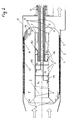
- Fig. 2 shows a longitudinal section through an inventive Plasma catalyst, which consists of a cylindrical, ceramic Honeycomb body 1 with an annular cross section and with corresponding swelling mats 2 and net-shaped end grids 3 from a steel mesh in a cylindrical metal housing 15 is embedded.
- the cylindrical interior of the Ceramic body is characterized by a conductive contact High voltage electrode formed, whereas the outer Cylinder surface of the ceramic body by the same Contacting, the electrode connected to the earth potential represents.
- the upstream entrance of the through the inner cylinder jacket is formed by a cavity fastened in this cavity by means of ceramic cement 6 Ceramic stopper 5 closed.
- the downstream one The end of the cavity is with a ceramic plug 7 closed, which has a bore into which a ceramic Pipe 8 is fixed by means of ceramic cement.
- the pipe 8 is passed through the metal housing 15 gas-tight due to O-ring seals 12. Through this tube 8 is done the supply of electrical voltage from the outside to High voltage electrode 9, preferably in four of each other electrically separated, cylindrical segments 9a, 9b, 9c and 9d is divided.
- Electrode segments 9a to 9d take place via steel wires 10a to 10d for each electrode part individually, with the steel wires through four perforated ceramic discs (in the drawing not visible) be kept at a distance.
- the PTK resistor 13 on the grounded side of the Monolith (1) also contributes to the uniform distribution of the contribute to the current of monoliths by dividing areas with increased current also increased ohmic power in the PTK resistor 13 and thus have a higher temperature, which means the positive temperature characteristic of the PTK resistor 13 the current is cut off.
Landscapes
- Engineering & Computer Science (AREA)
- Chemical & Material Sciences (AREA)
- Combustion & Propulsion (AREA)
- Chemical Kinetics & Catalysis (AREA)
- Health & Medical Sciences (AREA)
- Mechanical Engineering (AREA)
- Toxicology (AREA)
- General Engineering & Computer Science (AREA)
- Biomedical Technology (AREA)
- Environmental & Geological Engineering (AREA)
- Analytical Chemistry (AREA)
- General Chemical & Material Sciences (AREA)
- Oil, Petroleum & Natural Gas (AREA)
- Exhaust Gas After Treatment (AREA)
- Treating Waste Gases (AREA)
Applications Claiming Priority (3)
| Application Number | Priority Date | Filing Date | Title |
|---|---|---|---|
| AT0036897U AT2330U1 (de) | 1997-06-17 | 1997-06-17 | Vorrichtung zur dissoziation von im abgas von verbrennungskraftmaschinen enthaltenen stickstoffoxiden |
| AT36897U | 1997-06-17 | ||
| AT368/97U | 1997-06-17 |
Publications (3)
| Publication Number | Publication Date |
|---|---|
| EP0885647A2 true EP0885647A2 (fr) | 1998-12-23 |
| EP0885647A3 EP0885647A3 (fr) | 1999-04-07 |
| EP0885647B1 EP0885647B1 (fr) | 2003-09-17 |
Family
ID=3488747
Family Applications (1)
| Application Number | Title | Priority Date | Filing Date |
|---|---|---|---|
| EP98890174A Expired - Lifetime EP0885647B1 (fr) | 1997-06-17 | 1998-06-10 | Dispositif pour la dissociation d'oxydes d'azote dans le gaz d'échappement de moteurs à combustion |
Country Status (3)
| Country | Link |
|---|---|
| EP (1) | EP0885647B1 (fr) |
| AT (1) | AT2330U1 (fr) |
| DE (1) | DE59809616D1 (fr) |
Cited By (5)
| Publication number | Priority date | Publication date | Assignee | Title |
|---|---|---|---|---|
| WO2003018176A1 (fr) * | 2001-08-25 | 2003-03-06 | Accentus Plc | Reacteur plasma non thermique |
| US6678818B1 (en) | 1999-05-03 | 2004-01-13 | Stmicroelectronics S.A. | Decoding next instruction of different length without length mode indicator change upon length change instruction detection |
| EP1426102A3 (fr) * | 2002-11-21 | 2005-08-24 | HONDA MOTOR CO., Ltd. | Procédé pour dimineur le taux de particules dans des gaz d'échappement d'un moteur à combustion pauvre ou analogue |
| WO2006130895A1 (fr) * | 2005-06-08 | 2006-12-14 | Fleck Carl M | Procede et dispositif pour decomposer des oxydes d'azote dans un flux de gaz d'echappement |
| US7776140B2 (en) | 2005-06-08 | 2010-08-17 | Fleck Carl M | Device for removing soot particles from an exhaust gas stream |
Citations (2)
| Publication number | Priority date | Publication date | Assignee | Title |
|---|---|---|---|---|
| EP0332609A2 (fr) | 1988-03-11 | 1989-09-13 | Fleck, Carl Maria, Prof. Dr. | Filtre de gaz d'échappement de diesel |
| WO1997005369A1 (fr) | 1995-07-27 | 1997-02-13 | Fleck Carl M | Procede et dispositif pour la decomposition des oxydes d'azote dans les gaz d'echappement de moteurs a combustion interne |
Family Cites Families (11)
| Publication number | Priority date | Publication date | Assignee | Title |
|---|---|---|---|---|
| HU182826B (en) * | 1981-12-07 | 1984-03-28 | Csepeli Autogyar | Method and apparatus for decreasing the effect of environmental pollution of exhaust gases |
| US4945721A (en) * | 1988-04-14 | 1990-08-07 | Environmental Research International, Inc. | Electromagnetic converter for reduction of exhaust emissions |
| DE68906508T2 (de) * | 1988-10-05 | 1993-09-09 | Mitsubishi Heavy Ind Ltd | Abgasbehandlungsapparat. |
| US4999998A (en) * | 1989-01-17 | 1991-03-19 | E-Quad, Inc. | Method and apparatus for elimination of toxic oxides from exhaust gases |
| EP0379760A1 (fr) * | 1989-01-26 | 1990-08-01 | Univerzita Komenskeho | Dispositif pour réduire continuellement la concentration de monoxyde de carbone et d'autres émissions nocives |
| US5284556A (en) * | 1991-05-01 | 1994-02-08 | Plasmachines, Inc. | Exhaust treatment system and method |
| DE4231581A1 (de) * | 1992-09-21 | 1994-03-24 | Siemens Ag | Verfahren zur plasmachemischen Zersetzung und/oder Vernichtung von Schadstoffen, insbesondere zur Abgasreinigung von Verbrennungsmotoren oder anderer mit fossilem Treibstoff betriebenen Maschinen, sowie zugehörige Vorrichtung |
| JPH06178914A (ja) * | 1992-12-14 | 1994-06-28 | Mitsubishi Heavy Ind Ltd | 排ガス処理装置 |
| DE19518970C1 (de) * | 1995-05-23 | 1996-11-21 | Fraunhofer Ges Forschung | Verfahren und Vorrichtung zur Behandlung von Abgas |
| US5746984A (en) * | 1996-06-28 | 1998-05-05 | Low Emissions Technologies Research And Development Partnership | Exhaust system with emissions storage device and plasma reactor |
| US5914015A (en) * | 1996-07-15 | 1999-06-22 | Battelle Memorial Institute | Method and apparatus for processing exhaust gas with corona discharge |
-
1997
- 1997-06-17 AT AT0036897U patent/AT2330U1/de not_active IP Right Cessation
-
1998
- 1998-06-10 DE DE59809616T patent/DE59809616D1/de not_active Expired - Fee Related
- 1998-06-10 EP EP98890174A patent/EP0885647B1/fr not_active Expired - Lifetime
Patent Citations (2)
| Publication number | Priority date | Publication date | Assignee | Title |
|---|---|---|---|---|
| EP0332609A2 (fr) | 1988-03-11 | 1989-09-13 | Fleck, Carl Maria, Prof. Dr. | Filtre de gaz d'échappement de diesel |
| WO1997005369A1 (fr) | 1995-07-27 | 1997-02-13 | Fleck Carl M | Procede et dispositif pour la decomposition des oxydes d'azote dans les gaz d'echappement de moteurs a combustion interne |
Cited By (7)
| Publication number | Priority date | Publication date | Assignee | Title |
|---|---|---|---|---|
| US6678818B1 (en) | 1999-05-03 | 2004-01-13 | Stmicroelectronics S.A. | Decoding next instruction of different length without length mode indicator change upon length change instruction detection |
| WO2003018176A1 (fr) * | 2001-08-25 | 2003-03-06 | Accentus Plc | Reacteur plasma non thermique |
| EP1426102A3 (fr) * | 2002-11-21 | 2005-08-24 | HONDA MOTOR CO., Ltd. | Procédé pour dimineur le taux de particules dans des gaz d'échappement d'un moteur à combustion pauvre ou analogue |
| WO2006130895A1 (fr) * | 2005-06-08 | 2006-12-14 | Fleck Carl M | Procede et dispositif pour decomposer des oxydes d'azote dans un flux de gaz d'echappement |
| AT501876A1 (de) * | 2005-06-08 | 2006-12-15 | Fleck Carl M Dr | Verfahren und vorrichtung zum abbau von stickstoffoxiden in einem abgasstrom |
| AT501876B1 (de) * | 2005-06-08 | 2008-10-15 | Fleck Carl M Dr | Verfahren und vorrichtung zum abbau von stickstoffoxiden in einem abgasstrom |
| US7776140B2 (en) | 2005-06-08 | 2010-08-17 | Fleck Carl M | Device for removing soot particles from an exhaust gas stream |
Also Published As
| Publication number | Publication date |
|---|---|
| EP0885647B1 (fr) | 2003-09-17 |
| DE59809616D1 (de) | 2003-10-23 |
| EP0885647A3 (fr) | 1999-04-07 |
| AT2330U1 (de) | 1998-08-25 |
Similar Documents
| Publication | Publication Date | Title |
|---|---|---|
| EP0537219B1 (fr) | Procede et dispositif d'epuration des gaz d'echappement | |
| AT500959B1 (de) | Verfahren und filteranordnung zum abscheiden von russpartikeln | |
| EP2478194B1 (fr) | Dispositif pour purifier des gaz d'échappement avec deux corps en forme de nid d'abeilles pour génerer un potentiel électrique | |
| EP2310643B1 (fr) | Procédé de fonctionnement d'un dispositif comprenant au moins un corps en nid d'abeilles pouvant être chauffé électriquement | |
| EP0332609A2 (fr) | Filtre de gaz d'échappement de diesel | |
| DE68906508T2 (de) | Abgasbehandlungsapparat. | |
| EP0675272A1 (fr) | Dispositif d'allumage à préchambre | |
| DE19518970C1 (de) | Verfahren und Vorrichtung zur Behandlung von Abgas | |
| EP2616646B1 (fr) | Dispositif pour traiter des gaz d'échappement contenant des particules de suie | |
| EP0880642B1 (fr) | Dispositif de purification des gaz d'echappement d'un moteur a combustion interne | |
| AT409653B (de) | Verfahren und vorrichtung zum abscheiden von russpartikel aus einem abgasstrom, insbesondere einer diesel-brennkraftmaschine | |
| EP0885647B1 (fr) | Dispositif pour la dissociation d'oxydes d'azote dans le gaz d'échappement de moteurs à combustion | |
| EP2603678B1 (fr) | Procédé et dispositif pour réduire les particules de suie dans les gaz d'échappement d'un moteur à combustion interne | |
| EP2948253A1 (fr) | Dispositif et procédé destinés à traiter un gaz d'échappement comportant des particules | |
| DE602004004728T2 (de) | Nicht thermischer Plasmareaktor und Kraftfahrzeugabgasanlage mit einem solchen Reaktor | |
| EP0475288B1 (fr) | Dispositif d'allumage à jet de plasma | |
| EP0840838B1 (fr) | Procede et dispositif pour la decomposition des oxydes d'azote dans les gaz d'echappement de moteurs a combustion interne | |
| WO1997040265A1 (fr) | Procede et dispositif de traitement d'un effluent gazeux | |
| DE3829048A1 (de) | Verfahren und vorrichtung zum regenerieren eines russpartikel-abbrennfilter | |
| DE10353313B4 (de) | Vorrichtung und Verfahren zur selektiven katalytischen Reduktion der in einem Abgas einer Brennkraftmaschine enthaltenen Stickoxide | |
| AT405435B (de) | Verfahren zur abscheidung und verbrennung von russpartikeln aus dieselabgasen und dieselabgasfilter zur durchführung des verfahrens | |
| EP1990098A2 (fr) | Fitre à paroi avec une montée en pression faible | |
| DE102022117210A1 (de) | Vorrichtung zur Bereitstellung einer elektrischen Gas- oder Funkenentladung und Verfahren zur Zündung eines Brenners | |
| AT501876B1 (de) | Verfahren und vorrichtung zum abbau von stickstoffoxiden in einem abgasstrom | |
| DE102015226402A1 (de) | Zündvorrichtung zum Zünden eines Kraftstoff-Luft-Gemisches |
Legal Events
| Date | Code | Title | Description |
|---|---|---|---|
| PUAI | Public reference made under article 153(3) epc to a published international application that has entered the european phase |
Free format text: ORIGINAL CODE: 0009012 |
|
| AK | Designated contracting states |
Kind code of ref document: A2 Designated state(s): DE FR GB IT |
|
| AX | Request for extension of the european patent |
Free format text: AL;LT;LV;MK;RO;SI |
|
| PUAL | Search report despatched |
Free format text: ORIGINAL CODE: 0009013 |
|
| AK | Designated contracting states |
Kind code of ref document: A3 Designated state(s): AT BE CH CY DE DK ES FI FR GB GR IE IT LI LU MC NL PT SE |
|
| AX | Request for extension of the european patent |
Free format text: AL;LT;LV;MK;RO;SI |
|
| AKX | Designation fees paid | ||
| 17P | Request for examination filed |
Effective date: 19991228 |
|
| RBV | Designated contracting states (corrected) |
Designated state(s): AT BE CH CY LI |
|
| RBV | Designated contracting states (corrected) |
Designated state(s): DE FR GB IT |
|
| REG | Reference to a national code |
Ref country code: DE Ref legal event code: 8566 |
|
| GRAH | Despatch of communication of intention to grant a patent |
Free format text: ORIGINAL CODE: EPIDOS IGRA |
|
| RIC1 | Information provided on ipc code assigned before grant |
Ipc: 7B 01D 53/92 B Ipc: 7B 01J 19/08 B Ipc: 7F 01N 3/08 B Ipc: 7B 01D 53/32 A |
|
| RIC1 | Information provided on ipc code assigned before grant |
Ipc: 7B 01D 53/92 B Ipc: 7B 01J 19/08 B Ipc: 7F 01N 3/08 B Ipc: 7B 01D 53/32 A |
|
| GRAS | Grant fee paid |
Free format text: ORIGINAL CODE: EPIDOSNIGR3 |
|
| GRAA | (expected) grant |
Free format text: ORIGINAL CODE: 0009210 |
|
| AK | Designated contracting states |
Kind code of ref document: B1 Designated state(s): DE FR GB IT |
|
| REG | Reference to a national code |
Ref country code: GB Ref legal event code: FG4D Free format text: NOT ENGLISH |
|
| REF | Corresponds to: |
Ref document number: 59809616 Country of ref document: DE Date of ref document: 20031023 Kind code of ref document: P |
|
| GBT | Gb: translation of ep patent filed (gb section 77(6)(a)/1977) |
Effective date: 20031204 |
|
| ET | Fr: translation filed | ||
| PLBE | No opposition filed within time limit |
Free format text: ORIGINAL CODE: 0009261 |
|
| STAA | Information on the status of an ep patent application or granted ep patent |
Free format text: STATUS: NO OPPOSITION FILED WITHIN TIME LIMIT |
|
| 26N | No opposition filed |
Effective date: 20040618 |
|
| PGFP | Annual fee paid to national office [announced via postgrant information from national office to epo] |
Ref country code: IT Payment date: 20080621 Year of fee payment: 11 |
|
| PGFP | Annual fee paid to national office [announced via postgrant information from national office to epo] |
Ref country code: DE Payment date: 20080730 Year of fee payment: 11 |
|
| PGFP | Annual fee paid to national office [announced via postgrant information from national office to epo] |
Ref country code: FR Payment date: 20080529 Year of fee payment: 11 |
|
| PGFP | Annual fee paid to national office [announced via postgrant information from national office to epo] |
Ref country code: GB Payment date: 20080630 Year of fee payment: 11 |
|
| GBPC | Gb: european patent ceased through non-payment of renewal fee |
Effective date: 20090610 |
|
| REG | Reference to a national code |
Ref country code: FR Ref legal event code: ST Effective date: 20100226 |
|
| PG25 | Lapsed in a contracting state [announced via postgrant information from national office to epo] |
Ref country code: FR Free format text: LAPSE BECAUSE OF NON-PAYMENT OF DUE FEES Effective date: 20090630 |
|
| PG25 | Lapsed in a contracting state [announced via postgrant information from national office to epo] |
Ref country code: GB Free format text: LAPSE BECAUSE OF NON-PAYMENT OF DUE FEES Effective date: 20090610 |
|
| PG25 | Lapsed in a contracting state [announced via postgrant information from national office to epo] |
Ref country code: DE Free format text: LAPSE BECAUSE OF NON-PAYMENT OF DUE FEES Effective date: 20100101 |
|
| PG25 | Lapsed in a contracting state [announced via postgrant information from national office to epo] |
Ref country code: IT Free format text: LAPSE BECAUSE OF NON-PAYMENT OF DUE FEES Effective date: 20090610 |