EP0885672A2 - Procédé d'enlèvement de rivet poincinnantes - Google Patents
Procédé d'enlèvement de rivet poincinnantes Download PDFInfo
- Publication number
- EP0885672A2 EP0885672A2 EP98304331A EP98304331A EP0885672A2 EP 0885672 A2 EP0885672 A2 EP 0885672A2 EP 98304331 A EP98304331 A EP 98304331A EP 98304331 A EP98304331 A EP 98304331A EP 0885672 A2 EP0885672 A2 EP 0885672A2
- Authority
- EP
- European Patent Office
- Prior art keywords
- pin
- male die
- die end
- workpiece
- punch rivet
- Prior art date
- Legal status (The legal status is an assumption and is not a legal conclusion. Google has not performed a legal analysis and makes no representation as to the accuracy of the status listed.)
- Granted
Links
- 238000000034 method Methods 0.000 title claims abstract description 35
- 230000004927 fusion Effects 0.000 claims abstract description 6
- 238000001816 cooling Methods 0.000 claims abstract description 5
- 238000003466 welding Methods 0.000 claims description 24
- 238000010438 heat treatment Methods 0.000 claims description 5
- 238000003825 pressing Methods 0.000 claims description 5
- 230000006698 induction Effects 0.000 claims description 4
- 238000004140 cleaning Methods 0.000 claims description 3
- 238000005476 soldering Methods 0.000 claims 1
- 239000002184 metal Substances 0.000 description 16
- 230000008569 process Effects 0.000 description 8
- 238000005520 cutting process Methods 0.000 description 7
- 230000006378 damage Effects 0.000 description 4
- 230000000694 effects Effects 0.000 description 3
- 239000000463 material Substances 0.000 description 3
- 230000007246 mechanism Effects 0.000 description 3
- 230000008439 repair process Effects 0.000 description 2
- 230000008901 benefit Effects 0.000 description 1
- 238000010276 construction Methods 0.000 description 1
- 238000005553 drilling Methods 0.000 description 1
- 239000004922 lacquer Substances 0.000 description 1
- 230000035515 penetration Effects 0.000 description 1
- 239000011241 protective layer Substances 0.000 description 1
- 238000004064 recycling Methods 0.000 description 1
- 238000000926 separation method Methods 0.000 description 1
- 229910000679 solder Inorganic materials 0.000 description 1
- 238000003892 spreading Methods 0.000 description 1
- 230000007480 spreading Effects 0.000 description 1
Images

Classifications
-
- B—PERFORMING OPERATIONS; TRANSPORTING
- B21—MECHANICAL METAL-WORKING WITHOUT ESSENTIALLY REMOVING MATERIAL; PUNCHING METAL
- B21J—FORGING; HAMMERING; PRESSING METAL; RIVETING; FORGE FURNACES
- B21J15/00—Riveting
- B21J15/02—Riveting procedures
- B21J15/025—Setting self-piercing rivets
-
- B—PERFORMING OPERATIONS; TRANSPORTING
- B21—MECHANICAL METAL-WORKING WITHOUT ESSENTIALLY REMOVING MATERIAL; PUNCHING METAL
- B21J—FORGING; HAMMERING; PRESSING METAL; RIVETING; FORGE FURNACES
- B21J15/00—Riveting
- B21J15/38—Accessories for use in connection with riveting, e.g. pliers for upsetting; Hand tools for riveting
- B21J15/50—Removing or cutting devices for rivets
-
- Y—GENERAL TAGGING OF NEW TECHNOLOGICAL DEVELOPMENTS; GENERAL TAGGING OF CROSS-SECTIONAL TECHNOLOGIES SPANNING OVER SEVERAL SECTIONS OF THE IPC; TECHNICAL SUBJECTS COVERED BY FORMER USPC CROSS-REFERENCE ART COLLECTIONS [XRACs] AND DIGESTS
- Y10—TECHNICAL SUBJECTS COVERED BY FORMER USPC
- Y10T—TECHNICAL SUBJECTS COVERED BY FORMER US CLASSIFICATION
- Y10T29/00—Metal working
- Y10T29/49—Method of mechanical manufacture
- Y10T29/49789—Obtaining plural product pieces from unitary workpiece
- Y10T29/4979—Breaking through weakened portion
-
- Y—GENERAL TAGGING OF NEW TECHNOLOGICAL DEVELOPMENTS; GENERAL TAGGING OF CROSS-SECTIONAL TECHNOLOGIES SPANNING OVER SEVERAL SECTIONS OF THE IPC; TECHNICAL SUBJECTS COVERED BY FORMER USPC CROSS-REFERENCE ART COLLECTIONS [XRACs] AND DIGESTS
- Y10—TECHNICAL SUBJECTS COVERED BY FORMER USPC
- Y10T—TECHNICAL SUBJECTS COVERED BY FORMER US CLASSIFICATION
- Y10T29/00—Metal working
- Y10T29/49—Method of mechanical manufacture
- Y10T29/49789—Obtaining plural product pieces from unitary workpiece
- Y10T29/49792—Dividing through modified portion
-
- Y—GENERAL TAGGING OF NEW TECHNOLOGICAL DEVELOPMENTS; GENERAL TAGGING OF CROSS-SECTIONAL TECHNOLOGIES SPANNING OVER SEVERAL SECTIONS OF THE IPC; TECHNICAL SUBJECTS COVERED BY FORMER USPC CROSS-REFERENCE ART COLLECTIONS [XRACs] AND DIGESTS
- Y10—TECHNICAL SUBJECTS COVERED BY FORMER USPC
- Y10T—TECHNICAL SUBJECTS COVERED BY FORMER US CLASSIFICATION
- Y10T29/00—Metal working
- Y10T29/49—Method of mechanical manufacture
- Y10T29/49815—Disassembling
- Y10T29/49822—Disassembling by applying force
-
- Y—GENERAL TAGGING OF NEW TECHNOLOGICAL DEVELOPMENTS; GENERAL TAGGING OF CROSS-SECTIONAL TECHNOLOGIES SPANNING OVER SEVERAL SECTIONS OF THE IPC; TECHNICAL SUBJECTS COVERED BY FORMER USPC CROSS-REFERENCE ART COLLECTIONS [XRACs] AND DIGESTS
- Y10—TECHNICAL SUBJECTS COVERED BY FORMER USPC
- Y10T—TECHNICAL SUBJECTS COVERED BY FORMER US CLASSIFICATION
- Y10T29/00—Metal working
- Y10T29/49—Method of mechanical manufacture
- Y10T29/49826—Assembling or joining
- Y10T29/49863—Assembling or joining with prestressing of part
- Y10T29/49865—Assembling or joining with prestressing of part by temperature differential [e.g., shrink fit]
Definitions
- the present invention relates to a method of removing a punch rivet, which is set into a workpiece and has a male die end for driving the punch rivet and an opposite female die end.
- the invention further relates to a device for carrying out this method.
- a punch rivet for use in the method according to the invention is described and illustrated in DE OS 43 33 052 and has a flat, plate-like head at its male die end.
- the edge of the head upon which the tool for driving in the punch rivet presses, is pressed into the relevant workpiece while the female die end provided with a cutting edge pierces the workpiece, the cutting edge spreading radially outwards upon penetration of the female die end into the workpiece, so that the riveted joint is complete.
- German patent application 197 01 780.0 a punch rivet has been proposed which is provided in an axially symmetric design with cutting edges at both ends.
- the female die end pierces the workpiece with its cutting edge, while the male die end is deformed radially outwards so that the riveted joint is produced at this side of the punch rivet.
- punch rivets are moreover known, for example punch rivets according to DE PS 39 42 482 with a curved head at the male die end.
- the invention provides a method of removing a punch rivet, which is set into a workpiece and has a male die end for driving the punch rivet and an opposite female die end which penetrates into the workpiece, characterised in that a pin is placed with its front end onto the male die end so as substantially to cover the latter and, with a simultaneous supply of energy through the pin, heats the contact area between pin and male die end up to a fusion temperature in the contact area, whereupon after cooling of the contact area the pin is retracted counter to the pressure of an abutment supported on the workpiece and carries along the punch rivet which is thereby withdrawn from the workpiece.
- the unavoidable deformation caused in the immediate area around the riveted joint by tearing the rivet out of its riveted joint is restricted by the abutment to the area of the riveted joint, the abutment preventing a wider effect upon the workpiece.
- the energy supply is preferably effected by current conduction through the pin.
- the current conduction may be used to effect an arc weld or a resistance weld in the contact area between pin and male die end.
- the pin in the usual manner when arc welding studs, is pressed against the male die end, moved away from the latter to strike an arc and then moved back onto the contact area, where the arc produces a molten mass, into which the pin then dips so that the materials of the pin and the male die end of the punch rivet fuse together. It is also possible to use the energy supply to effect a resistance weld in the contact area between pin and male die end.
- the unavoidable electrical resistance in the contact area is utilised to heat the point with a strong current to such an extent that, ultimately, the contact area is heated up to the fusion temperature.
- a further possibility of producing heat in the contact area between pin and male die end is to heat the pin by induction heating, the pin again effecting the energy supply to the contact area between pin and male die end.
- Induction heating is advantageously effected by means of a coil, which surrounds the pin and is supplied with a suitable alternating current. Such induction heating makes it possible to produce a soldered joint in the contact area, it being naturally necessary to supply the solder for the purpose to the contact area either prior to mounting of the pin or afterwards from the side.
- a further possibility of supplying energy through the pin is to press the pin in rotation while pressing onto the male die end in such a way as to produce a friction weld in the contact area.
- a device for carrying out the method using arc welding advantageously comprises a stud welding gun, which holds the pin as an electrode and with its motion drive moves the pin axially back and forth while supplying power. It is possible to use as the device a standard stud welding gun such as is disclosed, for example, in GB PS 636 343.
- a device comprising a rotary tool, which holds and rotates the pin while pressing it against the male die end is advantageously used.
- the tool is therefore one which is similar to a drilling machine, into which the pin is clamped and which presses with the pin against the male die end so that the pin rotates with its front end on the male die end and sufficient heat is supplied through the pin to ultimately produce a rotary friction weld.
- the head is advantageously designed in such a way that it is provided with a central recess for receiving a correspondingly shaped projection at the front end of the pin so that the pin may be mounted centrally onto the male die end.
- This design automatically centres the pin relative to the punch rivet so that the defined position of the pin relative to the male die end required for the welding process is guaranteed. This facilitates handling of the relevant device for effecting the method according to the invention, especially when friction welding is involved.
- the method according to the invention may be used to particular advantage when the parts connected by punch rivets are car body parts which, for example following an accident, are in need of repair, in which case individual body parts frequently have to be exchanged.
- the method described above which enables riveted joints used for fastening the relevant body parts together to be detached from one another easily and without wider damage to said body parts, after which the still usable body part remaining on the car is subsequently provided with a new body part to replace the damaged one.
- the remaining body part is still quite capable of being joined to the new body part because it has not been significantly damaged by the previously described separation process. It is of course necessary for the connection between said two body parts to be effected by a different method, for example by riveting using larger rivets, especially blind rivets, or by a bolted connection.
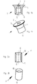
- Figure la shows a rivet 1 of a design such as is disclosed in DE OS 43 33 052 but with an additional central recess 2.
- the punch rivet 1 has at its one end, namely the male die end 3, the plate-like head 4. The opposite end is formed by the female die end 5 having the cutting edge 6.
- the recess 2 is used to guide the pin, more details of which are provided further below.
- Figure 1b shows a perspective view of the punch rivet 1.
- FIG 2a shows another form of construction of a punch rivet 7 which is axially symmetric.
- Figure 2b the same punch rivet is shown in a perspective view.
- the punch rivet 7 has at its one end the male die end 8 and at its opposite end the female die end 9. Both the male die end 8 and the female die end 9 are provided with a circumferential cutting edge, 10 and 11 respectively.
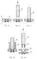
- FIG 3 shows the riveted joint of two metal sheets 12 and 13 (which form the workpiece) by means of the punch rivet 14, which is based on the punch rivet 1 according to Figures 1a and 1b.
- the punch rivet 14 is pressed at its male die end 15 with its plate-like head into the metal sheet 12, while at the female die end 16 the cutting edge 17 is spread radially outwards, thereby creating the riveted joint.
- Said riveted joint is of a known design.
- Figure 3b shows the riveted joint according to Figure 3a being approached by the pin 18.
- the pin 18 at its front end 19 has the projection 20 which fits into the recess 21 in the male die end 15 (see reference numeral 2 in Figure 1a).
- Figure 3c shows the same riveted joint with the pin 18 placed onto the male die end 15, a connection between pin 18 and rivet 14 effected by arc welding being indicated in the drawing by the bold line 21 situated in the contact area between pin 18 and male die end 15.
- Said weld situated in the contact area 21 between the front end 19 and male die end 15 was effected by moving the pin 18, in the manner customary when welding studs using arc welding, into contact with the punch rivet 14 so as to strike an arc which, by retracting the pin 18 for several milliseconds, was provided with the necessary burning time to cause the front face 19 of the pin 18 and the surface of the male die end 15 of the punch rivet 14 to fuse together.
- This is then followed in the customary manner by lowering of the pin 18 into the molten mass thus formed and by a subsequent cooling process, with the result that a strong, loadable connection is established between the pin 18 and the punch rivet 14.
- Figure 3d shows the start of removal of the punch rivet 14 from the riveted joint during which, after the abutment 22 is placed onto the top metal sheet 12, a pull is exerted on the pin 18 in the direction of the arrow in the drawing with the result that the punch rivet 14 is withdrawn from its riveted joint.
- the metal sheet 12 and the metal sheet 13 underneath are practically unable to deform so that there is only specific residual damage of the two metal sheets 12 and 13 at the seat point of the rivet 14.
- the remaining region of the two metal sheets 12 and 13 remains unaffected by the process.
- the strong connection between the pin 18 and the punch rivet 14 produced by the weld prevents the pin 18 from being torn off the punch rivet 14 so that ultimately the punch rivet 14 is withdrawn completely from the riveted joint.
- FIG 3e Removal of the punch rivet 14 is illustrated in Figure 3e, which shows the two metal sheets 12 and 13 separated from one another and, at a remove, the withdrawn punch rivet 14 still attached to the pin 18.
- the two metal sheets 12 and 13 are disconnected and may then be taken off for further treatment of some kind, in particular recycling, because, apart from the damage caused by the punch rivet 14 at the relevant point, the metal sheets 12 and 13 have not otherwise been altered in any way.
- Figures 4a to 4e the same processes as were illustrated in Figures 3a to 3e are reproduced only, here, they relate to the treatment of a punch rivet according to Figures 2a and 2b.
- the processes of placing the pin 18 onto the punch rivet 23, welding the pin 18 and the punch rivet 23 together and removing the punch rivet 23 from the riveted joint are identical to the process steps shown in Figures 3a to 3e, reference may be made to the description of the appropriate Figures 3a to 3e.
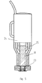
- a stud welding gun 24 is advantageously used.
- a stud welding gun is described, for example, in GB PS 636 343.
- the stud welding gun 24 has the chuck 25, which grips the pin 18 and permits execution of the axial movements which are required during arc welding and are effected by the known motion mechanism housed in the interior of the stud welding gun 24.
- the pin 18, as already mentioned above, is first moved onto the punch rivet, here the punch rivet 23, to strike the arc and then, after a sufficiently long burning time of the arc, the pin 18 is moved onto the punch rivet 23 to produce the required weld in the contact area between pin 18 and the male die end of the punch rivet 23.
- a tool of the type shown in Figure 5 may alternatively be used to produce a resistance weld, the tool merely having to be equipped with a suitable power supply and a suitable motion mechanism. Such tools are likewise prior art.
- a tool similar to that shown in Figure 5 may also be used for friction welding.
- the tool 24 is provided with a rotary mechanism, which sets the pin 18 held by the chuck 25 in rotation and presses said pin against the punch rivet 23 until sufficient heat is generated in the relevant contact area to produce a weld.
Landscapes
- Engineering & Computer Science (AREA)
- Mechanical Engineering (AREA)
- Insertion Pins And Rivets (AREA)
- Automatic Assembly (AREA)
- Hand Tools For Fitting Together And Separating, Or Other Hand Tools (AREA)
- Perforating, Stamping-Out Or Severing By Means Other Than Cutting (AREA)
- Forging (AREA)
Priority Applications (1)
| Application Number | Priority Date | Filing Date | Title |
|---|---|---|---|
| EP01108473A EP1114683A3 (fr) | 1997-06-19 | 1998-06-02 | Procédé d'enlèvement de rivets poinçonnants |
Applications Claiming Priority (2)
| Application Number | Priority Date | Filing Date | Title |
|---|---|---|---|
| DE19726104A DE19726104A1 (de) | 1997-06-19 | 1997-06-19 | Verfahren zum Entfernen von in ein Werkzeug gesetzten Stanznieten |
| DE19726104 | 1997-06-19 |
Related Child Applications (1)
| Application Number | Title | Priority Date | Filing Date |
|---|---|---|---|
| EP01108473A Division EP1114683A3 (fr) | 1997-06-19 | 1998-06-02 | Procédé d'enlèvement de rivets poinçonnants |
Publications (3)
| Publication Number | Publication Date |
|---|---|
| EP0885672A2 true EP0885672A2 (fr) | 1998-12-23 |
| EP0885672A3 EP0885672A3 (fr) | 2000-05-17 |
| EP0885672B1 EP0885672B1 (fr) | 2004-02-25 |
Family
ID=7833054
Family Applications (2)
| Application Number | Title | Priority Date | Filing Date |
|---|---|---|---|
| EP98304331A Expired - Lifetime EP0885672B1 (fr) | 1997-06-19 | 1998-06-02 | Procédé d'enlèvement de rivets poinçonnants |
| EP01108473A Withdrawn EP1114683A3 (fr) | 1997-06-19 | 1998-06-02 | Procédé d'enlèvement de rivets poinçonnants |
Family Applications After (1)
| Application Number | Title | Priority Date | Filing Date |
|---|---|---|---|
| EP01108473A Withdrawn EP1114683A3 (fr) | 1997-06-19 | 1998-06-02 | Procédé d'enlèvement de rivets poinçonnants |
Country Status (5)
| Country | Link |
|---|---|
| US (1) | US6108890A (fr) |
| EP (2) | EP0885672B1 (fr) |
| JP (2) | JP4063406B2 (fr) |
| AT (1) | ATE260157T1 (fr) |
| DE (2) | DE19726104A1 (fr) |
Cited By (3)
| Publication number | Priority date | Publication date | Assignee | Title |
|---|---|---|---|---|
| WO2001030516A1 (fr) * | 1999-10-26 | 2001-05-03 | Toyota Jidosha Kabushiki Kaisha | Rivet, structure de joint rivetee, appareil de rivetage et procede de rivetage |
| EP1136155A3 (fr) * | 2000-03-16 | 2002-02-06 | Emhart Inc. | Procédé et dispositif d'enlèvement de rivets poinçonnants |
| CN106077405A (zh) * | 2016-06-08 | 2016-11-09 | 广州华德汽车弹簧有限公司 | 铆钉自动上料机构 |
Families Citing this family (12)
| Publication number | Priority date | Publication date | Assignee | Title |
|---|---|---|---|---|
| DE19701780A1 (de) * | 1997-01-20 | 1998-07-23 | Emhart Inc | Stanzniet und mit ihm erstellte Nietverbindungen sowie Nietwerkzeug und Verfahrensherstellung einer Nietverbindung |
| DE10060390B4 (de) * | 2000-12-05 | 2012-04-19 | Volkswagen Ag | Stanznietverfahren |
| JP2004358523A (ja) * | 2003-06-05 | 2004-12-24 | Nippon Pop Rivets & Fasteners Ltd | 締結した自己穿孔型リベットを補修し、取外し、ソリッドリベットを締結する装置 |
| GB2426802B (en) * | 2005-05-31 | 2008-07-16 | Newfrey Llc | A blind rivet, removal system and removal method |
| RU2308345C2 (ru) * | 2005-10-26 | 2007-10-20 | Мемжанов Николай Османович | Способ соединения деталей и силовая точка соединения |
| US10005120B2 (en) | 2012-07-16 | 2018-06-26 | Henrob Limited | Method for forming a joint using a self-piercing rivet |
| CN103706753A (zh) * | 2013-12-31 | 2014-04-09 | 泰信电机(苏州)有限公司 | 一种电机去铆钉装置 |
| US20150217821A1 (en) * | 2014-02-06 | 2015-08-06 | Ford Global Technologies, Llc | Method of Setting Vehicle Geometry and Structural Joining |
| JP6460235B2 (ja) * | 2015-07-01 | 2019-01-30 | 新日鐵住金株式会社 | 機械的接合装置及び機械的接合方法 |
| CN106112543B (zh) * | 2016-07-19 | 2018-04-10 | 上海交通大学 | 用于自冲摩擦铆焊的铆钉及其自冲摩擦铆焊连接系统 |
| DE102016118109A1 (de) * | 2016-09-26 | 2018-03-29 | Newfrey Llc | Fügeverfahren zum vorlochfreien Verbinden von wenigstens einem ersten Bauteil mit einem zweiten Bauteil |
| CN121042845A (zh) * | 2025-11-05 | 2025-12-02 | 江西犀瑞制造有限公司 | 一种剃须刀头护罩及分配器一体装配组装机 |
Citations (4)
| Publication number | Priority date | Publication date | Assignee | Title |
|---|---|---|---|---|
| GB636343A (en) | 1947-05-01 | 1950-04-26 | Harold Martin | Improvements in and relating to the welding of metal studs and the like to metal plates and the like |
| DE3942482C1 (fr) | 1989-12-22 | 1991-01-24 | Ulrich 2359 Henstedt-Ulzburg De Schildknecht | |
| DE4333052A1 (de) | 1993-09-29 | 1995-03-30 | Audi Ag | Selbststanzende Befestigungsvorrichtung |
| DE19701780A1 (de) | 1997-01-20 | 1998-07-23 | Emhart Inc | Stanzniet und mit ihm erstellte Nietverbindungen sowie Nietwerkzeug und Verfahrensherstellung einer Nietverbindung |
Family Cites Families (4)
| Publication number | Priority date | Publication date | Assignee | Title |
|---|---|---|---|---|
| US4138909A (en) * | 1977-12-02 | 1979-02-13 | Stephen Johnson | Bolt extractor |
| US5125144A (en) * | 1989-05-11 | 1992-06-30 | Clark Brian J | Extractor for broken-off taps and the like and method of extracting same |
| DE4320068C1 (de) * | 1993-06-17 | 1994-12-15 | Audi Ag | Verfahren und Vorrichtung zur Reparatur von Fahrzeugkarosserien aus Leichtmetallteilen |
| DE19653151C2 (de) * | 1996-12-19 | 2001-02-22 | Bayerische Motoren Werke Ag | Verfahren und Vorrichtung zum Entfernen einer Niete |
-
1997
- 1997-06-19 DE DE19726104A patent/DE19726104A1/de not_active Withdrawn
-
1998
- 1998-06-02 AT AT98304331T patent/ATE260157T1/de not_active IP Right Cessation
- 1998-06-02 EP EP98304331A patent/EP0885672B1/fr not_active Expired - Lifetime
- 1998-06-02 DE DE1998621830 patent/DE69821830T2/de not_active Expired - Lifetime
- 1998-06-02 EP EP01108473A patent/EP1114683A3/fr not_active Withdrawn
- 1998-06-18 US US09/099,142 patent/US6108890A/en not_active Expired - Lifetime
- 1998-06-19 JP JP17249998A patent/JP4063406B2/ja not_active Expired - Lifetime
-
2001
- 2001-04-13 JP JP2001115179A patent/JP2001293535A/ja active Pending
Patent Citations (4)
| Publication number | Priority date | Publication date | Assignee | Title |
|---|---|---|---|---|
| GB636343A (en) | 1947-05-01 | 1950-04-26 | Harold Martin | Improvements in and relating to the welding of metal studs and the like to metal plates and the like |
| DE3942482C1 (fr) | 1989-12-22 | 1991-01-24 | Ulrich 2359 Henstedt-Ulzburg De Schildknecht | |
| DE4333052A1 (de) | 1993-09-29 | 1995-03-30 | Audi Ag | Selbststanzende Befestigungsvorrichtung |
| DE19701780A1 (de) | 1997-01-20 | 1998-07-23 | Emhart Inc | Stanzniet und mit ihm erstellte Nietverbindungen sowie Nietwerkzeug und Verfahrensherstellung einer Nietverbindung |
Cited By (4)
| Publication number | Priority date | Publication date | Assignee | Title |
|---|---|---|---|---|
| WO2001030516A1 (fr) * | 1999-10-26 | 2001-05-03 | Toyota Jidosha Kabushiki Kaisha | Rivet, structure de joint rivetee, appareil de rivetage et procede de rivetage |
| US6988862B1 (en) | 1999-10-26 | 2006-01-24 | Toyota Jidosha Kabushiki Kaisha | Rivet, riveted joint structure riveting apparatus, and riveting method |
| EP1136155A3 (fr) * | 2000-03-16 | 2002-02-06 | Emhart Inc. | Procédé et dispositif d'enlèvement de rivets poinçonnants |
| CN106077405A (zh) * | 2016-06-08 | 2016-11-09 | 广州华德汽车弹簧有限公司 | 铆钉自动上料机构 |
Also Published As
| Publication number | Publication date |
|---|---|
| EP1114683A2 (fr) | 2001-07-11 |
| DE69821830D1 (de) | 2004-04-01 |
| EP0885672A3 (fr) | 2000-05-17 |
| EP1114683A3 (fr) | 2001-10-24 |
| JP2001293535A (ja) | 2001-10-23 |
| DE69821830T2 (de) | 2005-01-13 |
| EP0885672B1 (fr) | 2004-02-25 |
| US6108890A (en) | 2000-08-29 |
| DE19726104A1 (de) | 1998-12-24 |
| ATE260157T1 (de) | 2004-03-15 |
| JP4063406B2 (ja) | 2008-03-19 |
| JPH1190853A (ja) | 1999-04-06 |
Similar Documents
| Publication | Publication Date | Title |
|---|---|---|
| US6108890A (en) | Method of removing punch rivets set into a workpiece | |
| JP6533855B2 (ja) | 抵抗溶接ファスナ、装置及び方法 | |
| EP0526164B1 (fr) | Joint de soudure par arc entre un support et un élément métallique | |
| JP6646679B2 (ja) | 同種材料及び異種材料を接合するための抵抗溶接ファスナ、装置及び方法 | |
| US5739498A (en) | Method of and apparatus for joining plate members by the use of anchor pegs | |
| US5387774A (en) | Spot resistance-welding electrode; contact tip for such an electrode; machine for exchanging these tips | |
| US6417490B1 (en) | Method and device for thermally supporting mechanical joints | |
| EP0624418B1 (fr) | Soudage par friction | |
| CZ200854A3 (cs) | Zarízení pro spojování kovových desek a zpusob spojování kovových desek | |
| JP2014512971A (ja) | コーティングされたブランクの機械的コーティング除去方法および装置 | |
| US6568062B1 (en) | Methods of removing self-piercing rivets set into a workpiece and devices for implementing the methods | |
| EP1033501A2 (fr) | Rivet aveugle | |
| EP1463601B1 (fr) | Materiau et procede de soudage sans support | |
| US7748590B2 (en) | Ultrasonic welding apparatus | |
| Lathabai | Joining of aluminium and its alloys | |
| JP2018126752A (ja) | リベットを用いた接合方法とその実施に使用する装置 | |
| EP0561571A1 (fr) | Procédé de soudage | |
| JPH10305373A (ja) | シーム溶接方法および装置 | |
| CA2619626C (fr) | Systeme et methode de soudage par points par resistance a decharge | |
| EP0778106B1 (fr) | Méthode de réparation par soudage et appareil de rechargement par soudage pour structure métallique | |
| JPH07144284A (ja) | スポット溶接ガンのチップ交換方法及び装置 | |
| KR101799797B1 (ko) | 스터드 용접방법 | |
| CN212371399U (zh) | 闪光对焊机 | |
| JPH01133692A (ja) | 摩擦溶接方法及び装置 | |
| EP2992981A1 (fr) | Procédé d'enlèvement de rivets notamment pour installation à impulsion magnétique pour rivetage avec chauffage |
Legal Events
| Date | Code | Title | Description |
|---|---|---|---|
| PUAI | Public reference made under article 153(3) epc to a published international application that has entered the european phase |
Free format text: ORIGINAL CODE: 0009012 |
|
| AK | Designated contracting states |
Kind code of ref document: A2 Designated state(s): AT BE DE DK ES FR GB IE IT NL PT SE |
|
| AX | Request for extension of the european patent |
Free format text: AL;LT;LV;MK;RO;SI |
|
| PUAL | Search report despatched |
Free format text: ORIGINAL CODE: 0009013 |
|
| AK | Designated contracting states |
Kind code of ref document: A3 Designated state(s): AT BE CH CY DE DK ES FI FR GB GR IE IT LI LU MC NL PT SE |
|
| AX | Request for extension of the european patent |
Free format text: AL;LT;LV;MK;RO;SI |
|
| RIC1 | Information provided on ipc code assigned before grant |
Free format text: 7B 21J 15/50 A, 7B 23K 9/20 B, 7B 23K 9/00 B, 7B 23K 20/12 B, 7B 23K 11/00 B |
|
| 17P | Request for examination filed |
Effective date: 20001117 |
|
| AKX | Designation fees paid |
Free format text: AT BE DE DK ES FR GB IE IT NL PT SE |
|
| 17Q | First examination report despatched |
Effective date: 20020321 |
|
| RAP1 | Party data changed (applicant data changed or rights of an application transferred) |
Owner name: EMHART LLC |
|
| RAP1 | Party data changed (applicant data changed or rights of an application transferred) |
Owner name: BAYERISCHE MOTOREN WERKE AKTIENGESELLSCHAFT |
|
| GRAP | Despatch of communication of intention to grant a patent |
Free format text: ORIGINAL CODE: EPIDOSNIGR1 |
|
| GRAS | Grant fee paid |
Free format text: ORIGINAL CODE: EPIDOSNIGR3 |
|
| GRAA | (expected) grant |
Free format text: ORIGINAL CODE: 0009210 |
|
| AK | Designated contracting states |
Kind code of ref document: B1 Designated state(s): AT BE DE DK ES FR GB IE IT NL PT SE |
|
| PG25 | Lapsed in a contracting state [announced via postgrant information from national office to epo] |
Ref country code: NL Free format text: LAPSE BECAUSE OF FAILURE TO SUBMIT A TRANSLATION OF THE DESCRIPTION OR TO PAY THE FEE WITHIN THE PRESCRIBED TIME-LIMIT Effective date: 20040225 Ref country code: BE Free format text: LAPSE BECAUSE OF FAILURE TO SUBMIT A TRANSLATION OF THE DESCRIPTION OR TO PAY THE FEE WITHIN THE PRESCRIBED TIME-LIMIT Effective date: 20040225 Ref country code: AT Free format text: LAPSE BECAUSE OF FAILURE TO SUBMIT A TRANSLATION OF THE DESCRIPTION OR TO PAY THE FEE WITHIN THE PRESCRIBED TIME-LIMIT Effective date: 20040225 |
|
| REG | Reference to a national code |
Ref country code: GB Ref legal event code: FG4D |
|
| REG | Reference to a national code |
Ref country code: IE Ref legal event code: FG4D |
|
| REF | Corresponds to: |
Ref document number: 69821830 Country of ref document: DE Date of ref document: 20040401 Kind code of ref document: P |
|
| PG25 | Lapsed in a contracting state [announced via postgrant information from national office to epo] |
Ref country code: SE Free format text: LAPSE BECAUSE OF FAILURE TO SUBMIT A TRANSLATION OF THE DESCRIPTION OR TO PAY THE FEE WITHIN THE PRESCRIBED TIME-LIMIT Effective date: 20040525 Ref country code: DK Free format text: LAPSE BECAUSE OF FAILURE TO SUBMIT A TRANSLATION OF THE DESCRIPTION OR TO PAY THE FEE WITHIN THE PRESCRIBED TIME-LIMIT Effective date: 20040525 |
|
| PG25 | Lapsed in a contracting state [announced via postgrant information from national office to epo] |
Ref country code: IE Free format text: LAPSE BECAUSE OF NON-PAYMENT OF DUE FEES Effective date: 20040602 |
|
| PG25 | Lapsed in a contracting state [announced via postgrant information from national office to epo] |
Ref country code: ES Free format text: LAPSE BECAUSE OF FAILURE TO SUBMIT A TRANSLATION OF THE DESCRIPTION OR TO PAY THE FEE WITHIN THE PRESCRIBED TIME-LIMIT Effective date: 20040605 |
|
| NLV1 | Nl: lapsed or annulled due to failure to fulfill the requirements of art. 29p and 29m of the patents act | ||
| ET | Fr: translation filed | ||
| PLBE | No opposition filed within time limit |
Free format text: ORIGINAL CODE: 0009261 |
|
| STAA | Information on the status of an ep patent application or granted ep patent |
Free format text: STATUS: NO OPPOSITION FILED WITHIN TIME LIMIT |
|
| 26N | No opposition filed |
Effective date: 20041126 |
|
| REG | Reference to a national code |
Ref country code: IE Ref legal event code: MM4A |
|
| PG25 | Lapsed in a contracting state [announced via postgrant information from national office to epo] |
Ref country code: PT Free format text: LAPSE BECAUSE OF NON-PAYMENT OF DUE FEES Effective date: 20040725 |
|
| PGFP | Annual fee paid to national office [announced via postgrant information from national office to epo] |
Ref country code: IT Payment date: 20120626 Year of fee payment: 15 |
|
| PG25 | Lapsed in a contracting state [announced via postgrant information from national office to epo] |
Ref country code: IT Free format text: LAPSE BECAUSE OF NON-PAYMENT OF DUE FEES Effective date: 20130602 |
|
| REG | Reference to a national code |
Ref country code: FR Ref legal event code: PLFP Year of fee payment: 19 |
|
| REG | Reference to a national code |
Ref country code: FR Ref legal event code: PLFP Year of fee payment: 20 |
|
| PGFP | Annual fee paid to national office [announced via postgrant information from national office to epo] |
Ref country code: DE Payment date: 20170624 Year of fee payment: 20 Ref country code: FR Payment date: 20170621 Year of fee payment: 20 Ref country code: GB Payment date: 20170626 Year of fee payment: 20 |
|
| REG | Reference to a national code |
Ref country code: DE Ref legal event code: R071 Ref document number: 69821830 Country of ref document: DE |
|
| REG | Reference to a national code |
Ref country code: GB Ref legal event code: PE20 Expiry date: 20180601 |
|
| PG25 | Lapsed in a contracting state [announced via postgrant information from national office to epo] |
Ref country code: GB Free format text: LAPSE BECAUSE OF EXPIRATION OF PROTECTION Effective date: 20180601 |