EP0885705A1 - Herstellungsverfahren von mikroprismenmatrixen - Google Patents
Herstellungsverfahren von mikroprismenmatrixen Download PDFInfo
- Publication number
- EP0885705A1 EP0885705A1 EP96925108A EP96925108A EP0885705A1 EP 0885705 A1 EP0885705 A1 EP 0885705A1 EP 96925108 A EP96925108 A EP 96925108A EP 96925108 A EP96925108 A EP 96925108A EP 0885705 A1 EP0885705 A1 EP 0885705A1
- Authority
- EP
- European Patent Office
- Prior art keywords
- master mold
- flat sheets
- flat
- roof
- sheets
- Prior art date
- Legal status (The legal status is an assumption and is not a legal conclusion. Google has not performed a legal analysis and makes no representation as to the accuracy of the status listed.)
- Granted
Links
Images


Classifications
-
- B—PERFORMING OPERATIONS; TRANSPORTING
- B29—WORKING OF PLASTICS; WORKING OF SUBSTANCES IN A PLASTIC STATE IN GENERAL
- B29C—SHAPING OR JOINING OF PLASTICS; SHAPING OF MATERIAL IN A PLASTIC STATE, NOT OTHERWISE PROVIDED FOR; AFTER-TREATMENT OF THE SHAPED PRODUCTS, e.g. REPAIRING
- B29C33/00—Moulds or cores; Details thereof or accessories therefor
- B29C33/30—Mounting, exchanging or centering
- B29C33/301—Modular mould systems [MMS], i.e. moulds built up by stacking mould elements, e.g. plates, blocks, rods
- B29C33/302—Assembling a large number of mould elements to constitute one cavity
-
- B—PERFORMING OPERATIONS; TRANSPORTING
- B29—WORKING OF PLASTICS; WORKING OF SUBSTANCES IN A PLASTIC STATE IN GENERAL
- B29C—SHAPING OR JOINING OF PLASTICS; SHAPING OF MATERIAL IN A PLASTIC STATE, NOT OTHERWISE PROVIDED FOR; AFTER-TREATMENT OF THE SHAPED PRODUCTS, e.g. REPAIRING
- B29C33/00—Moulds or cores; Details thereof or accessories therefor
- B29C33/38—Moulds or cores; Details thereof or accessories therefor characterised by the material or the manufacturing process
- B29C33/3842—Manufacturing moulds, e.g. shaping the mould surface by machining
- B29C33/3857—Manufacturing moulds, e.g. shaping the mould surface by machining by making impressions of one or more parts of models, e.g. shaped articles and including possible subsequent assembly of the parts
-
- B—PERFORMING OPERATIONS; TRANSPORTING
- B29—WORKING OF PLASTICS; WORKING OF SUBSTANCES IN A PLASTIC STATE IN GENERAL
- B29C—SHAPING OR JOINING OF PLASTICS; SHAPING OF MATERIAL IN A PLASTIC STATE, NOT OTHERWISE PROVIDED FOR; AFTER-TREATMENT OF THE SHAPED PRODUCTS, e.g. REPAIRING
- B29C33/00—Moulds or cores; Details thereof or accessories therefor
- B29C33/38—Moulds or cores; Details thereof or accessories therefor characterised by the material or the manufacturing process
- B29C33/40—Plastics, e.g. foam or rubber
-
- G—PHYSICS
- G02—OPTICS
- G02B—OPTICAL ELEMENTS, SYSTEMS OR APPARATUS
- G02B5/00—Optical elements other than lenses
- G02B5/04—Prisms
- G02B5/045—Prism arrays
-
- G—PHYSICS
- G02—OPTICS
- G02B—OPTICAL ELEMENTS, SYSTEMS OR APPARATUS
- G02B5/00—Optical elements other than lenses
- G02B5/12—Reflex reflectors
- G02B5/122—Reflex reflectors cube corner, trihedral or triple reflector type
- G02B5/124—Reflex reflectors cube corner, trihedral or triple reflector type plural reflecting elements forming part of a unitary plate or sheet
-
- B—PERFORMING OPERATIONS; TRANSPORTING
- B29—WORKING OF PLASTICS; WORKING OF SUBSTANCES IN A PLASTIC STATE IN GENERAL
- B29C—SHAPING OR JOINING OF PLASTICS; SHAPING OF MATERIAL IN A PLASTIC STATE, NOT OTHERWISE PROVIDED FOR; AFTER-TREATMENT OF THE SHAPED PRODUCTS, e.g. REPAIRING
- B29C33/00—Moulds or cores; Details thereof or accessories therefor
- B29C33/38—Moulds or cores; Details thereof or accessories therefor characterised by the material or the manufacturing process
- B29C33/3842—Manufacturing moulds, e.g. shaping the mould surface by machining
- B29C2033/385—Manufacturing moulds, e.g. shaping the mould surface by machining by laminating a plurality of layers
-
- B—PERFORMING OPERATIONS; TRANSPORTING
- B29—WORKING OF PLASTICS; WORKING OF SUBSTANCES IN A PLASTIC STATE IN GENERAL
- B29L—INDEXING SCHEME ASSOCIATED WITH SUBCLASS B29C, RELATING TO PARTICULAR ARTICLES
- B29L2011/00—Optical elements, e.g. lenses, prisms
- B29L2011/0083—Reflectors
- B29L2011/0091—Reflex reflectors
-
- Y—GENERAL TAGGING OF NEW TECHNOLOGICAL DEVELOPMENTS; GENERAL TAGGING OF CROSS-SECTIONAL TECHNOLOGIES SPANNING OVER SEVERAL SECTIONS OF THE IPC; TECHNICAL SUBJECTS COVERED BY FORMER USPC CROSS-REFERENCE ART COLLECTIONS [XRACs] AND DIGESTS
- Y10—TECHNICAL SUBJECTS COVERED BY FORMER USPC
- Y10S—TECHNICAL SUBJECTS COVERED BY FORMER USPC CROSS-REFERENCE ART COLLECTIONS [XRACs] AND DIGESTS
- Y10S425/00—Plastic article or earthenware shaping or treating: apparatus
- Y10S425/808—Lens mold
Definitions
- This invention relates to a method of making a microprism master mold for use in the production of cube-corner retroreflectors (i.e., articles reflecting most of the incident light back toward the light source).
- cube-corner retroreflectors i.e., articles reflecting most of the incident light back toward the light source.
- it relates to a method of making a microprism master mold which is suitable for use in the production of retroreflective elements useful in signs such as road signs and construction signs, license plates for vehicles such as automobiles and motorcycles, safety products such as safety clothing and life-saving devices, markings such as signboards, reflectors for visible light or laser light reflection sensors, and the like, as well as retroreflective sheeting composed of such retroreflective elements.
- retroreflective sheeting capable of reflecting incident light back toward the light source have been well known, and such sheeting is widely used in the above-described fields of application due to its retroreflectivity.
- retroreflective sheeting utilizing the retroreflection principle of prisms, such as cube-corner retroreflective sheeting has markedly higher optical retroreflection efficiency than conventional retroreflective sheeting using micro glass beads, and the range of its use is expanding every year because of its excellent retroreflection performance.
- cube-corner retroreflective elements exhibit high retroreflectivity, so long as the angle between the optical axis [i.e., an axis lying at an equal distance from three mutually perpendicular faces constituting the prismatic reflective elements (sometimes referred to simply as "prismatic element")] of a prismatic element and incident light (i.e., the entrance angle) is narrow.
- cube-corner retroreflective elements have the disadvantage that, as entrance angle increases, their retroreflection efficiency is reduced.
- This is a method in which a large number of metallic pins having a prism formed at the tip thereof are bundled to form an array of prisms.
- This method is characterized in that the design of the prism formed at the tip of each pin may be arbitrarily modified and is suitable for the production of relatively large prisms.
- it is not practical when the formation of, for example, more than 2,000 microprisms per square centimeter is required as dictated by the object of the present invention.
- This is a method of making a microprism mold of the hexagonal prism type which comprises stacking a plurality of flat sheets having two mutually parallel major surfaces, cutting therein V-shaped grooves in a direction perpendicular to the major surfaces and at a fixed pitch to form a series of successive roof-shaped projections having a vertical angle of about 90°, and then shifting the flat sheets so that the vertices of the roof-shaped projections formed on each flat sheet meet the bottoms of the V-shaped grooves formed on an adjacent flat sheet.
- This method is characterized by a relatively better design freedom, though it is lower than that of the bundled pin method.
- This method can improve the poor productivity in the fabrication of a prism mold which constitutes a disadvantage of the above-described bundled pin method.
- this method has the disadvantage that, in case of forming microprisms, the insufficient strength of flat sheets may cause them to become distorted during the cutting of V-shaped grooves, and has hence been used for the production of relatively large prisms.
- This method has frequently been employed for the production of conventional retroreflective sheeting using prismatic elements. The reasons for this are that it is relatively easy to form microprisms by cutting and that thin retroreflective sheeting may be obtained because it is possible to form an array in which the bases of the formed triangular prisms are arranged in a common plane.
- this method has the disadvantage that the prism shape which can be employed is limited to triangular prisms capable of being formed by V-groove cutting and its degree of design freedom is low.
- the basic properties desired for retroreflective sheeting include high reflectivity (i.e., the highness of reflective brightness as represented by the reflective brightness of light incident on the sheeting from a direction perpendicular to the surface thereof) and angularity.
- high reflectivity i.e., the highness of reflective brightness as represented by the reflective brightness of light incident on the sheeting from a direction perpendicular to the surface thereof
- angularity involve the following three considerations.
- a first consideration relating to angularity is observation angularity.
- the location of the viewer is usually different from that of the light source. Accordingly, more intense light must reach the viewer positioned away from the axis of the entrance light. Therefore it is required that the reduction in reflectivity should be limited even at the location of wide observation angle to the axis of the incident light.
- a second consideration relating to angularity is entrance angularity. For example, as an automobile is approaching closer to a traffic sign, the entrance angle of light emitted by the headlights of the automobile to the sign increases gradually, and the intensity of the light reaching the driver being the viewer decreases correspondingly. In order to cause the sign to retain sufficiently high reflectivity even when the driver approaches to the sign, excellent entrance angularity are required.
- a third consideration relating to angularity is rotational angularity.
- a phenomenon peculiar to prismatic elements is such that retroreflectivity varies according to the direction from which light is incident on the retroreflective sheeting. Consequently, retroreflective sheeting involves a troublesome problem which is that the sheeting should be applied in control of the direction of the sheeting in applying it to signs.
- Micro glass bead type retroreflective sheeting does not involve this problem because the reflective elements have the form of a body of revolution.
- prismatic retroreflective sheeting is characterized in that the right retroreflectivity thereof is two to three times as higher as that of bead type retroreflective sheeting, but it is generally said to have poor angularity.
- the angle of incidence must be relatively close to 0°, i.e., light must be incident on the retroreflective sheeting from a direction substantially perpendicular to the surface thereof. If the angle of incidence becomes greater, the light may fail to reach a second or third reflective lateral face and escape out of the prism, resulting in a reduction in retroreflection efficiency.
- the angle of incidence exceeds a certain limit, the conditions for total internal reflection are not satisfied, so that the incident light passes to the back side of the prism.
- Rotational angularity pose a serious problem especially in the case of triangular prisms.
- a method in which the prism array surface is divided into plural sections of certain size and derections of sections are changed each other see U.S. Pat. No. 4,243,618).
- the rotation angle of light incident on the prisms differs from section to section, and the reflectivity varies correspondingly.
- a whole reflectivity is leveled to give uniform rotational angularity.
- the sections of the prism array surface can be rather clearly seen from the front side of the retroreflective sheeting, and hence have the disadvantage that the appearance of the sheeting is reduced in attractiveness.
- the prismatic elements have a minute size, for example, of 500 ⁇ m or less.
- a minute size for example, of 500 ⁇ m or less.
- the triangular prism method permits the formation of minute prisms, but it is difficult to carry out the design of prisms having excellent angularity as is another object of the present invention.
- a method of making a cube-corner microprism master mold which comprises stacking a plurality of flat sheets having two mutually parallel major surfaces, cutting V-shaped grooves on one lateral surface of the resulting flat sheet stack in a direction perpendicular to the major surfaces and at a fixed pitch to form a series of successive roof-shaped projections having a vertical angle of about 90°, and then shifting the flat sheets so that the vertices of the roof-shaped projections formed on each flat sheet meet the bottoms of the V-shaped grooves formed on an adjacent flat sheet, characterized in that the flat sheets used have a thickness of 50 to 500 ⁇ m and in that the flat sheets are made of a synthetic resin having a Rockwell hardness of not less than 70.
- FIG. 1(A) symmetrical V-shaped grooves 2 and roof-shaped projections 4 are successively formed in the upper part of a flat sheet 1 at a fixed repeating pitch (L).
- Numeral 3 designates the bottom of each V-shaped groove 2 and numeral 5 designates the vertex of each roof-shaped projection 4.
- the distance between the bottom 3 of a V-shaped groove 2 and the vertex 5 of an adjacent roof-shaped projection 4, as measured in the lateral direction of the drawing, is equal to one-half of the repeating pitch (L).
- the bottom angle ⁇ of V-shaped grooves 2 and the vertical angle ⁇ of roof-shaped projections 4 are both equal to about 90°, and ( ⁇ + ⁇ ) is equal to 180°.
- Numeral 6 designates the projection of the optical axis of a formed prism on this sectional view.
- the thickness of the flat sheet is designated by W and the depth of the V-shaped grooves by D.
- asymmetrical V-shaped grooves 2 and roof-shaped projections 4 are successively formed in the upper part of a flat sheet 1 at an equal repeating pitch (L).
- the tilt angle of V-shaped grooves 2 is designated by ⁇ .
- ⁇ and ⁇ designate the bottom angle of V-shaped grooves 2 and the vertical angle of roof-shaped projections 4.
- ⁇ and ⁇ are each equal to about 90°, and ( ⁇ + ⁇ ) is equal to 180°.
- Numeral 6 designates the projection of the optical axis of a prism on this sectional view, and the projection of the tilt angle of the optical axis of the prism on this sectional view coincides with the tilt angle ⁇ of the V-shaped grooves.
- the tilt angle ⁇ of the V-shaped grooves is expressed by one-half of the difference between unilateral cutting angles ⁇ 1 and ⁇ 2
- the bottom angle ⁇ of the V-shaped grooves is expressed by the sum of unilateral cutting angles ⁇ 1 and ⁇ 2 .
- ⁇ 1 and ⁇ 2 may be varied in the respective ranges defined by 45° ⁇ ⁇ 1 ⁇ 60°, preferably 45° ⁇ ⁇ 1 ⁇ 55°, and 30° ⁇ ⁇ 2 ⁇ 45°, preferably 35° ⁇ ⁇ 2 ⁇ 45°. Accordingly, the tilt angle ⁇ may be varied in the range defined by 0° ⁇ ⁇ ⁇ 15°, preferably 0° ⁇ ⁇ ⁇ 10°.
- a flat sheet block 7 is formed by stacking a plurality of flat sheets 1. Then, as illustrated in FIG. 4, this block 7 is firmly secured with a fastening jig 8 so that flat sheets 1 will not move during cutting. Subsequently, according to a suitable cutting process such as a fly cutting process, a lateral surface of block 7 in which the edge surfaces of flat sheets 1 extending in the direction of the thickness thereof are exposed (i.e., the upper lateral surface in FlG.4 ) are planed together with fastening jig 8 so that the planed surface will generally have a degree of flatness within 1 ⁇ m and preferably within 0.5 ⁇ m. Thereafter, as illustrated in FIG.
- V-shaped grooves 2 are cut in the planed surface so that symmetrical roof-shaped projections 4 having a vertical angle ( ⁇ ) of 90° are formed in a direction perpendicular to the major surface of flat sheets 1 and at a fixed pitch (L).
- the cutting of V-shaped grooves may be performed, for example, according to a fly cutting process using a cutting tool having diamond mounted at its tip.
- the accuracy of cutting should preferably be such that the resin microprisms formed with the prism master mold obtained by this process will have an average surface roughness (Ra) of not greater than 0.05 ⁇ m and more preferably not greater than 0.01 ⁇ m.
- each flat sheet is shifted in a direction parallel to the major surface of the flat sheet by one-half (1/2L) of the cutting pitch (L) as illustrated in FIG. 7, and further shifted in the vertical direction by the cutting depth (D) as illustrated in FIG. 8, so that the vertices 5 of the series of roof-shaped projections formed on each flat sheet are made to meet the bottom 3 of the V-shaped grooves in the series of roof-shaped projections formed on an adjacent flat sheet.
- a microprism master mold 9 is formed.
- the vertical angle ( ⁇ ) thereof need not necessarily be exactly equal to 90°, but may be varied slightly from 90°, for example, in the range of about 89.8° to 90.2°. This can spread the beam of retroreflected light and thereby bring about an improvement in observation angle characteristics.
- V-shaped grooves having a desired tilt angle i.e., an angle of deviation from a direction perpendicular to the surface of the retroreflective sheeting ( ⁇ ) may be formed by cutting them while tilting the center line of each V-shaped groove (i.e., the bisector of the bottom angle of the V-shaped groove which corresponds to line 6 shown in FIG. 2) suitably to the right or left side.
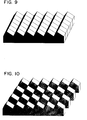
- asymmetrical roof-shaped projections 4 as illustrated in FIGs. 2 and 9 can be formed.
- Such asymmetrical V-shaped grooves may be cut by using a cutting tool having a tip angle of about 90° while tilting it by a desired tilt angle, or by cutting each V-shaped groove on one side after the other with a cutting tool having a definite acute tip angle while tilting it by a desired tilt angle. In the latter case, V-shaped grooves having any desired tilt angle can be cut, provided that the sum of the two unilateral cutting angles is adjusted to about 90°.
- each flat sheet is shifted by L 1 in a rightward direction parallel to the major surface of the flat sheet (or by L 2 in a leftward direction parallel to the major surfaces of the flat sheet) as illustrated in FIG. 7, and further shifted in the vertical direction by the cutting depth (D) as illustrated in FIG. 8, so that the vertices of the series of roof-shaped projections formed on each flat sheet are made to meet the bottom 3 of the V-shaped grooves in the series of roof-shaped projections formed on an adjacent flat sheet.
- a microprism master mold as illustrated in FIG. 10 can be formed.
- the tilt angle ( ⁇ ) thereof is expressed by a negative value
- the tilt angle ( ⁇ ) thereof is expressed by a positive value
- the tilt angle ( ⁇ ) of the V-shaped grooves should preferably be in the range of -15° to +15° and more preferably -10° to +10°, inclusive of the case in which the V-shaped grooves are not tilted (i.e., the tilt angle thereof is 0°).
- roof-shaped projections may be cut on a stack of flat sheets in which adjacent flat sheets are previously displaced from each other by a distance to be shifted in a direction parallel to the major surface of the flat sheets after cutting.
- a microprism master mold can be formed by rearranging the flat sheets so as to eliminate the mutual displacement thereof, and then shifting the flat sheets in the vertical direction by the cutting depth so that the vertices of the series of roof-shaped projections formed on each flat sheet meet the bottom of the V-shaped grooves in the series of roof-shaped projections formed on an adjacent flat sheet.
- the formation of a microprism master mold is carried out by using flat sheets having smooth major surfaces and a thickness of 50 to 500 ⁇ m. If the thickness of the flat sheet is less than 50 ⁇ m, the formed prisms have an unduly small aperture size and hence present the disadvantage that the beam of retroreflected light is excessively spread by a diffraction effect to cause a reduction in the retroreflectivity of the prisms. If the thickness of the flat sheet is greater than 500 ⁇ m, it is generally impossible to form thin and flexible prismatic retroreflective sheeting. Preferably, the thickness of the flat sheet is in the range of 60 to 200 ⁇ m. Moreover, the flat sheet used need not have an identical thickness, but two or more types of flat sheets having different thicknesses may be used in combination.
- the present invention is characterized by using flat sheets made of a specific material, i.e., flat sheets made of a synthetic resin having a Rockwell hardness (JIS Z2245) of not less than 70 and preferably not less than 75.
- a specific material i.e., flat sheets made of a synthetic resin having a Rockwell hardness (JIS Z2245) of not less than 70 and preferably not less than 75.
- the synthetic resins which can suitably be used for the fabrication of flat sheets in the present invention are preferably thermoplastic or thermosetting synthetic resins which have not only the above-defined hardness but also a glass transition temperature of 150°C or above and more preferably 200°C or above. For example, they seldom have the disadvantage of softening during cutting and thereby making high precision cutting difficult.
- Preferred examples thereof include polyethylene terephthalate resin, polybutylene terephthalate resin, polycarbonate resins, polymethyl methacrylate resin, polyimide resins, polyarylate resins, polyethersulfone resins, polyetherimide resins and cellulose triacetate resin.
- polyethylene terephthalate resin, polymethyl methacrylate resin and polycarbonate resins are suitable for practical purposes because of their availability, processability and the like.
- suitable modifiers, processing aids and the like may be added to the above-described synthetic resins.
- the fabrication of flat sheets from a synthetic resin as described above may be carried out according to an ordinary resin forming technique such as extrusion molding, calendering or solution casting. If necessary, the resulting flat sheets may be subjected to additional treatments such as heat treatment and stretching.
- the major surfaces of the flat sheets so fabricated may be subjected to a preliminary conductivity treatment, in order to facilitate a conductivity treatment and/or an electroforming process which will be carried out to form an electroformed mold from the prism master mold made by the method of the present invention.
- the preliminary conductivity treatment there may be employed vacuum evaporation involving the deposition of a metal such as gold, silver, copper, aluminum, zinc, chromium, nickel or selenium; cathode sputtering using such a metal; or electroless plating using copper or nickel.
- a metal such as gold, silver, copper, aluminum, zinc, chromium, nickel or selenium
- cathode sputtering using such a metal or electroless plating using copper or nickel.
- the flat sheets themselves may be made electrically conductive by incorporating an electrically conductive fine powder (e.g., carbon black) or an organic metallic salt into the synthetic resin.
- the surface of the synthetic resin microprism master mold made by the method of the present invention is subjected to an electroforming process for forming a metal coating thereon. Then, this metal coating may be removed from the surface of the master mold to obtain a metallic mold for use in the molding of, for example, microprismatic sheeting as a cube-corner retroreflector.
- the lateral faces of the master mold must be subjected to a conductivity treatment for imparting electrical conductivity thereto, prior to an electro-forming process.
- a conductivity treatment for imparting electrical conductivity thereto, prior to an electro-forming process.
- this conductivity treatment there may be employed, for example, silvering, electroless plating, vacuum evaporation or cathode sputtering.
- the surface of the master mold made in the above-described manner is cleaned with an alkaline detergent or the like to remove any contaminants (e.g., oily matter) therefrom, activated with a surface activator such as tannic acid, and then silvered quickly with the aid of a silver nitrate solution.
- an alkaline detergent or the like to remove any contaminants (e.g., oily matter) therefrom, activated with a surface activator such as tannic acid, and then silvered quickly with the aid of a silver nitrate solution.
- a spray process in which an aqueous solution of silver nitrate and an aqueous solution of a reducing agent (e.g., glucose or glyoxal) are sprayed with a double-cylinder nozzle gun, or a dipping process in which the master mold is dipped into a mixture of an aqueous solution of silver nitrate and an aqueous solution of a reducing agent.
- a reducing agent e.g., glucose or glyoxal
- the silver coating should preferably be as thin as possible, so long as electrical conductivity is secured during electroforming. For example, its thickness may be 0.1 ⁇ m or less.
- electroless plating copper, nickel and the like may be used.
- a water-soluble nickel salt such as nickel sulfate or nickel chloride may be used.
- a complexing agent comprising of a solution containing a salt of citric acid or malic acid as a principal component, and a reducing agent such as sodium hypophosphite, sodium borohydride or aminoborane are added to the plating solution.
- Vacuum evaporation may be carried out by cleaning the surface of the master mold in the same manner as for silvering, placing the master mold in a vacuum chamber, and vaporizing a metal (e.g., gold, silver, copper, aluminum, zinc, nickel, chromium or selenium) therein by the application of heat to deposit it on the cooled surface of the master mold and thereby form an electrically conductive coating.
- Cathode sputtering may be carried out by using a vacuum chamber provided therein with a smooth cathode plate on which a desired metal foil can be mounted, and an anode stand made of a metal such as aluminum or iron and serving to place thereon a material to be treated.
- the master mold pretreated in the same manner as for silvering is placed on the anode stand, and a metal foil similar to that used for vacuum evaporation is mounted on the cathode and a voltage is applied thereto so as to cause a glow discharge.
- the resulting stream of positive ions is made to impinge on the metal foil of the cathode, so that metal atoms or fine metal particles are evaporated and deposited on the surface of the master mold to form an electrically conductive coating thereon.
- the electrically conductive coatings formed by these methods may have a thickness of, for example, 300 ⁇ .
- the whole surface of the master mold must be uniformly subjected to the above-described conductivity treatment. If the conductivity treatment is not uniform, defects may develop, for example, in that the smoothness of the surface of the electroformed layer is reduced or the formation of an electroformed layer is omitted, in regions having poor electrical conductivity.
- the surface to be silvered is treated with a solvent such as alcohol to improve its wettability by the silvering solution.
- a solvent such as alcohol
- the synthetic resin prism master mold made according to the present invention has very deep and sharp recesses, its improvement in wettability tends to be insufficient. Defects of the electrically conductive coating due to the shape of such recesses also tend to develop during vacuum evaporation and the like.
- the flat sheets of synthetic resin stacked to form a master mold may fail to come into close contact with each other.
- defects tend to develop, for example, in that the electrically conductive coating formed on the surface of the master mold may be broken at the innerfaces between the flat sheets. All of these defects will interfere with the formation of a uniform electroformed layer.
- both major surfaces of the flat sheets of synthetic resin used for the formation of a master mold may be subjected to a preliminary conductivity treatment as described previously. Since this preliminary conductivity treatment serves to improve wettability by a silvering solution and, in particular, to improve electrical conductivity between sheets, it is particularly effective in eliminating defects due to poor contact of the sheets.
- the synthetic resin master mold having an electrically conductive coating formed thereon is subjected to various pretreatments so that uniform electroforming may be performed.
- an activation treatment is often carried out.
- this activation treatment there may be employed, for example, a method which comprises dipping the master mold into a 10 wt.% aqueous solution of sulfamic acid.
- the silver layer becomes integral with the electroformed layer and can hence be easily stripped from the synthetic resin master mold.
- an electrically conductive coating of nickel or the like is formed by electroless plating or cathode sputtering, the contact between the synthetic resin surface and the electrically conductive coating is so good that, after electroforming, it may be difficult to strip the electroformed layer from the synthetic resin layer. In such a situation, it is advisable to subject the electrically conductive coating to a so-called stripping treatment (e.g., a chromate treatment) prior to electroforming. In this case, the electrically conductive coating remains on the synthetic resin layer after the electroformed layer is stripped.
- stripping treatment e.g., a chromate treatment
- the synthetic resin prism master mold having an electrically conductive coating formed thereon is subjected to an electroforming process in which an electroformed layer is produced on the electrically conductive coating.
- the electroforming process is generally carried out, for example, in a 60 wt.% aqueous solution of nickel sulfamate and under conditions including a temperature of 40°C and a current density of about 10 A/dm 2 .
- a uniform electroformed layer can readily be obtained by adjusting the deposition rate of the electroformed layer, for example, to about 48 hours/mm or less. If the deposition rate is higher, defects such as poor smoothness of the surface and omissions in the electroformed layer tend to develop.
- nickel-cobalt alloys containing cobalt and other components may also be used in order to improve the surface abrasion resistance of the resulting mold.
- the Vickers hardness (Hv) of the resulting electroformed layer can be increased to 300-400 by adding 10-15% by weight of cobalt. Consequently, the durability of the mold can be improved when a synthetic resin is molded by use of the resulting electroformed mold to produce microprismatic sheeting as a retroreflector product.
- the first-generation electroformed mold made in the above-described manner may be repeatedly used as an electroforming master for making second-generation electroformed molds.
- a plurality of electroformed molds may be made from one prism master mold.
- a plurality of electroformed molds so made may be precisely cut into sections. These sections may be combined and joined together so as to give a final mold size suitable for the molding of a synthetic resin into microprismatic sheeting.
- joining purposes there may employed, for example, a method in which the cut ends are simply butted together, and a method in which the joints of the combined sections are welded according to a technique such as electron beam welding, YAG laser welding or carbon dioxide laser welding.
- the electroformed mold so combined is used as a mold for the molding of synthetic resins.
- the method for the molding of synthetic resins there may be employed compression molding or injection molding.
- Compression molding may be carried out, for example, by inserting a thin-walled electroformed mold formed of nickel, synthetic resin sheeting of predetermined thickness, and about 5 mm thick silicone rubber sheeting as a cushioning material into a compression molding press, preheating them for 30 seconds under a pressure equal to 10-20% of the molding pressure, and then heating and pressing them at a temperature of 180-250°C and a pressure of about 10-30 kg/cm 2 for about 2 minutes. Thereafter, they are cooled to room temperature in the pressed state and the pressure is released to obtain a molded prismatic product.
- an product in the form of continuous sheeting may also be produced as follows.
- a thin-walled (about 0.5 mm thick) electro-formed mold made in the above-described manner is joined according to a welding process as described above to form an endless belt mold.
- This belt mold is mounted on a pair of rolls comprising a heating roll and a cooling roll, and allowed to travel. While the belt mold is lying on the heating roll, a molten synthetic resin in the form of sheeting is fed thereto and pressed with one or more silicone rolls. Thereafter, the synthetic resin sheeting is cooled on the cooling roll to a temperature lower than its glass transition temperature and stripped from the belt mold to obtain a desired product.
- microprism master mold according to the plate method.
- the microprisms formed from the master mold made by the method of the present invention are hexagonal prisms, they show an increase in effective area contributing to retroreflection, as compared with triangular prisms which are commonly used in thin retroreflective sheeting. Consequently, they are characterized by higher reflectivity and rotational angularity.
- each sheet was first shifted in a direction parallel to the major surfaces of the sheet by one-half of the repeating pitch of the grooves (FIG. 7), and then shifted in the direction of the depth of the grooves by the depth of the grooves, so that the vertices of the series of roof-shaped projections formed on the sheet were made to meet the bottoms of the grooves in an adjacent series of roof-shaped projections.
- a microprism master mold made of polyethylene terephthalate was formed (FIG. 8).
- a microprism master mold made of polycarbonate was formed in the same manner as in Example 1, except that the polyethylene terephthalate sheets were replaced by polycarbonate sheets (with a Rockwell hardness of 75 and a softening point of 240°C) and having the same size (i.e., the same width, length and thickness).
- a microprism master mold made of polymethyl methacrylate was formed in the same manner as in Example 1, except that the polyethylene terephthalate sheets were replaced by polymethyl methacrylate sheets (with a Rockwell hardness of 98 and a softening point of 180°C) and having the same size.
- a microprism master mold made of polyethylene terephthalate sheets was formed in the same manner as in Example 1, except that flat sheets obtained by depositing gold on both major surfaces of polyethylene terephthalate sheeting having a thickness of 100 ⁇ m (i.e. the same thickness as that of the flat sheets used in Example 1) by vacuum evaporation and then cutting the sheeting into pieces having a width of 75 mm and a length of 200 mm were used.
- the surface of the prism master mold formed of polyethylene terephthalate sheets in Example 1 was cleaned with an alkaline detergent and activated with tannic acid used as a surface activator. Then, according to a spray method using a double-cylinder nozzle gun containing an aqueous solution of silver nitrate and an aqueous solution of a reducing agent, the surface of the master mold was silvered to form an electrically conductive coating thereon.
- this master mold having an electrically conductive coating formed thereon was dipped into a 10 wt.% aqueous solution of sulfamic acid to activate the surface of the electrically conductive coating, and then subjected to an electroforming process which was carried out in a 60 wt.% aqueous solution of nickel sulfamate at 40°C and 8 A/dm 2 for 48 hours.
- the electroformed layer obtained by the electroforming process was stripped from the master mold to obtain a 0.8 mm thick electroformed nickel mold having an array of cube-corner elements thereon.
- the electroformed mold thus obtained 0.5 mm thick polycarbonate sheeting, and about 5 mm thick silicone rubber sheeting as a cushioning material were inserted into a compression molding press heated to 250°C, preheated for 30 seconds under a pressure of 2 kg/cm 2 , and then compression-molded at a temperature of 240°C and a pressure of 20 kg/cm 2 about 10-30 kg/cm 2 for about 2 minutes. Thereafter, they were cooled to room temperature in the pressed state and the pressure is released to obtain polycarbonate prismatic sheeting useful as a retroreflector.
- Polycarbonate prismatic sheeting as a retroreflector was made in the same manner as in Example 5, except that the microprism master mold formed of polyethylene terephthalate sheets in Example 1 was replaced by the microprism master mold formed of polyethylene terephthalate sheets in Example 4.
Landscapes
- Engineering & Computer Science (AREA)
- Physics & Mathematics (AREA)
- Mechanical Engineering (AREA)
- General Physics & Mathematics (AREA)
- Optics & Photonics (AREA)
- Manufacturing & Machinery (AREA)
- Optical Elements Other Than Lenses (AREA)
- Moulds For Moulding Plastics Or The Like (AREA)
Applications Claiming Priority (4)
| Application Number | Priority Date | Filing Date | Title |
|---|---|---|---|
| JP211330/95 | 1995-07-28 | ||
| JP21133095 | 1995-07-28 | ||
| JP21133095 | 1995-07-28 | ||
| PCT/JP1996/002117 WO1997004939A1 (en) | 1995-07-28 | 1996-07-26 | Microprism matrix manufacturing method |
Publications (3)
| Publication Number | Publication Date |
|---|---|
| EP0885705A1 true EP0885705A1 (de) | 1998-12-23 |
| EP0885705A4 EP0885705A4 (de) | 2001-01-17 |
| EP0885705B1 EP0885705B1 (de) | 2003-05-02 |
Family
ID=16604172
Family Applications (1)
| Application Number | Title | Priority Date | Filing Date |
|---|---|---|---|
| EP96925108A Expired - Lifetime EP0885705B1 (de) | 1995-07-28 | 1996-07-26 | Herstellungsverfahren von mikroprismenmatrixen |
Country Status (6)
| Country | Link |
|---|---|
| US (1) | US6010609A (de) |
| EP (1) | EP0885705B1 (de) |
| JP (1) | JP3356290B2 (de) |
| CN (1) | CN1068822C (de) |
| DE (1) | DE69627895T2 (de) |
| WO (1) | WO1997004939A1 (de) |
Cited By (8)
| Publication number | Priority date | Publication date | Assignee | Title |
|---|---|---|---|---|
| US6015214A (en) * | 1996-05-30 | 2000-01-18 | Stimsonite Corporation | Retroreflective articles having microcubes, and tools and methods for forming microcubes |
| WO2003041934A1 (en) * | 2001-11-09 | 2003-05-22 | 3M Innovative Properties Company | Method for making a molded polymeric article |
| US6575584B1 (en) | 1999-05-28 | 2003-06-10 | Universite De Liege | Light guiding plate with internal micro-prisms |
| RU2239312C2 (ru) * | 2002-10-01 | 2004-11-10 | Верещагин Анатолий Николаевич | Рельефная поверхность пресс-формы для производства вощины |
| WO2006095161A3 (en) * | 2005-03-10 | 2006-12-21 | Rue De Int Ltd | Article and security device based on customised microprism film |
| WO2008082414A1 (en) * | 2007-01-04 | 2008-07-10 | General Electric Company | Methods for improving mold quality for use in the manufacture of light management film, manufactured film and corresponding mold |
| US7703179B2 (en) | 2001-11-09 | 2010-04-27 | 3M Innovative Properties Company | Microreplicated surface |
| IT201600103914A1 (it) * | 2016-10-17 | 2018-04-17 | Antonio Luigi Piero Maria Foresti | Stampo lamellare per stampaggio di materie plastiche |
Families Citing this family (49)
| Publication number | Priority date | Publication date | Assignee | Title |
|---|---|---|---|---|
| US6309580B1 (en) * | 1995-11-15 | 2001-10-30 | Regents Of The University Of Minnesota | Release surfaces, particularly for use in nanoimprint lithography |
| US6253442B1 (en) * | 1997-07-02 | 2001-07-03 | 3M Innovative Properties Company | Retroreflective cube corner sheeting mold and method for making the same |
| US5898523A (en) * | 1997-07-02 | 1999-04-27 | Minnesota Mining & Manufacturing Company | Tiled retroreflective sheeting composed of highly canted cube corner elements |
| US5981032A (en) | 1997-07-02 | 1999-11-09 | 3M Innovative Properties Company | Retroreflective cube corner sheeting mold and sheeting formed therefrom |
| WO1999001275A1 (en) | 1997-07-02 | 1999-01-14 | Minnesota Mining And Manufacturing Company | Cube corner sheeting mold and method of making the same |
| CA2295071A1 (en) | 1997-07-02 | 1999-01-14 | Kenneth L. Smith | Retroreflective cube corner sheeting, molds therefore, and methods of making the same |
| CN1190301C (zh) | 1997-08-25 | 2005-02-23 | 维尔克鲁工业公司 | 模腔的成形 |
| US6258311B1 (en) * | 1997-08-25 | 2001-07-10 | Velcro Industries B.V. | Forming mold cavities |
| US6274221B2 (en) * | 1999-01-29 | 2001-08-14 | 3M Innovative Properties Company | Angular brightness microprismatic retroreflective film or sheeting incorporating a syndiotactic vinyl aromatic polymer |
| US6540367B1 (en) | 1999-04-07 | 2003-04-01 | 3M Innovative Properties Company | Structured surface articles containing geometric structures with compound faces and methods for making same |
| JP4494648B2 (ja) | 1999-04-07 | 2010-06-30 | スリーエム イノベイティブ プロパティズ カンパニー | 複合面を有する幾何学的構造を含む構造化表面物品 |
| US6780001B2 (en) * | 1999-07-30 | 2004-08-24 | Formfactor, Inc. | Forming tool for forming a contoured microelectronic spring mold |
| US8728610B2 (en) | 2000-02-25 | 2014-05-20 | 3M Innovative Properties Company | Compound mold and structured surface articles containing geometric structures with compound faces and method of making same |
| JP4125889B2 (ja) * | 2000-12-04 | 2008-07-30 | 日本板硝子株式会社 | 光学素子、成形型及びそれらの製造方法 |
| DE10119671A1 (de) * | 2001-04-20 | 2002-10-24 | Sen Hans-Erich Gubela | Umlenkspiegelstruktur, bestehend aus einer Vielzahl von Tripeln |
| KR100490816B1 (ko) * | 2001-06-15 | 2005-05-24 | 샤프 가부시키가이샤 | 마이크로 코너 큐브 어레이, 마이크로 큐브 어레이의 제조방법 및 반사형 표시 장치 |
| JP2003262711A (ja) * | 2002-03-08 | 2003-09-19 | Seiko Epson Corp | 反射体およびその製造方法 |
| DE10216579A1 (de) * | 2002-04-14 | 2003-10-23 | Sen Hans-Erich Gubela | Weitwinkelsensorsystem mit Tripelreflektor und Herstellung der Werkzeuge |
| TW590999B (en) * | 2002-08-28 | 2004-06-11 | Alliance Fiber Optic Prod Inc | Mold for producing array optical fiber substrate with V-shaped grooves and method for producing the same |
| CN2566292Y (zh) * | 2002-09-03 | 2003-08-13 | 钱定榕 | 光束分配装置 |
| EP1623253A1 (de) | 2003-03-06 | 2006-02-08 | 3M Innovative Properties Company | Lamina mit würfeleckenelementen und retroreflektiven folien |
| US7156527B2 (en) | 2003-03-06 | 2007-01-02 | 3M Innovative Properties Company | Lamina comprising cube corner elements and retroreflective sheeting |
| US7174619B2 (en) * | 2003-03-06 | 2007-02-13 | 3M Innovative Properties Company | Methods of making microstructured lamina and apparatus |
| US7257877B2 (en) * | 2003-06-30 | 2007-08-21 | Nidec Sankyo Corporation | Grating forming method and manufacturing method for master member for manufacturing molding die |
| US8226880B2 (en) * | 2003-07-07 | 2012-07-24 | 10X Technology, Llc | Process for fabricating precise microstructures |
| US20050008821A1 (en) * | 2003-07-07 | 2005-01-13 | Pricone Robert M. | Process and apparatus for fabricating precise microstructures and polymeric molds for making same |
| JP2005119940A (ja) * | 2003-09-26 | 2005-05-12 | Nippon Sheet Glass Co Ltd | エッチング加工物品およびそれを用いた成形構造体並びにそれらの製造方法 |
| TW200528925A (en) * | 2004-02-20 | 2005-09-01 | Hon Hai Prec Ind Co Ltd | A manufacturing method of a light guide plate |
| US7179406B1 (en) * | 2004-03-08 | 2007-02-20 | Attar Adil H | Method and apparatus for making reflective pavement marker |
| WO2008021758A1 (en) * | 2006-08-11 | 2008-02-21 | Home Diagnostics, Inc. | Methods for fabricating a biosensor with a surface texture |
| WO2008023830A1 (en) | 2006-08-22 | 2008-02-28 | Nippon Carbide Kogyo Kabushiki Kaisha | Triangular pyramid type cubic corner retroreflection article, and its manufacturing method |
| CN101868741B (zh) * | 2007-08-24 | 2012-08-22 | 日本电石工业株式会社 | 角隅型回归反射物品 |
| CN101420829B (zh) * | 2007-10-25 | 2011-09-21 | 深圳富泰宏精密工业有限公司 | 金属外壳及其制作方法 |
| CN101456667B (zh) * | 2007-12-10 | 2011-12-21 | 鸿富锦精密工业(深圳)有限公司 | 棱镜片的制造方法 |
| TWI396623B (zh) * | 2007-12-21 | 2013-05-21 | Hon Hai Prec Ind Co Ltd | 稜鏡片及其製造方法 |
| WO2010067583A1 (ja) | 2008-12-08 | 2010-06-17 | 日本カーバイド工業株式会社 | 再帰反射物品 |
| US9289925B2 (en) * | 2009-04-10 | 2016-03-22 | 3M Innovative Properties Company | Methods of making hollow microneedle arrays and articles and uses therefrom |
| AU2010248533B2 (en) | 2009-05-11 | 2013-08-29 | Nippon Carbide Industries Co., Inc. | Hexagonal corner cube retroreflective article |
| CN101738661B (zh) * | 2009-12-29 | 2014-04-09 | 常州市日月反光材料有限公司 | 一种回归反射反光膜及其制造方法 |
| US11774648B2 (en) * | 2010-05-07 | 2023-10-03 | Pti Ip Llc | Corner-cube irradiation control |
| US10236658B2 (en) * | 2015-02-16 | 2019-03-19 | Alan Lenef | Light source utilizing wavelength conversion |
| CN105549538B (zh) * | 2015-12-09 | 2018-01-05 | 中国科学院重庆绿色智能技术研究院 | 微棱镜反光模具cam系统 |
| TWI756466B (zh) | 2017-08-29 | 2022-03-01 | 美商艾維利 丹尼森公司 | 用於基於投影機的顯示系統的回射片 |
| CN109423668A (zh) * | 2017-09-01 | 2019-03-05 | 泉州市同兴反光材料有限公司 | 一种制作反光模具的四方板工艺流程 |
| CN112318784A (zh) * | 2019-07-20 | 2021-02-05 | 浙江艾明德生物科技有限公司 | 一种硬模压贴三棱镜模具的制备方法 |
| JP7335127B2 (ja) * | 2019-10-17 | 2023-08-29 | 小島プレス工業株式会社 | 成形金型およびこの成形金型を用いて成形された樹脂部品 |
| CN111338015B (zh) * | 2020-04-17 | 2023-05-02 | 荆门市探梦科技有限公司 | 基于二维特征的反射式几何全息膜及其制备方法和应用 |
| WO2021208942A1 (zh) * | 2020-04-17 | 2021-10-21 | 荆门市探梦科技有限公司 | 基于二维特征的反射式几何全息膜及其制备方法和应用 |
| WO2022046134A1 (en) | 2020-08-27 | 2022-03-03 | Aura Optical System, LP | Microprismatic retroreflective mold, sheet, and article and methods of manufacture thereof |
Family Cites Families (17)
| Publication number | Priority date | Publication date | Assignee | Title |
|---|---|---|---|---|
| US2380447A (en) * | 1945-07-31 | Optical reflecting material | ||
| US1591572A (en) * | 1925-02-05 | 1926-07-06 | Jonathan C Stimson | Process and apparatus for making central triple reflectors |
| US2029375A (en) * | 1931-02-26 | 1936-02-04 | W P Montgomery | Reflector |
| US2968838A (en) * | 1959-01-29 | 1961-01-24 | Alan A Hicks | Three-dimensional die |
| US3069721A (en) | 1960-03-04 | 1962-12-25 | Ciba Ltd | Tools for making surface patterns |
| US3258840A (en) * | 1963-12-05 | 1966-07-05 | Hedgewick Peter | Method of making a core for molding reflectors |
| US3417959A (en) * | 1966-11-14 | 1968-12-24 | Minnesota Mining & Mfg | Die for forming retro-reflective article |
| US3922065A (en) * | 1968-05-31 | 1975-11-25 | Minnesota Mining & Mfg | Cube-corner retro-reflective article |
| US3712706A (en) * | 1971-01-04 | 1973-01-23 | American Cyanamid Co | Retroreflective surface |
| US4073568A (en) * | 1975-11-26 | 1978-02-14 | Ferro Corporation | Retroreflector units with three mutually perpendicular surfaces defining a trihedral angle of a rectangular parallelepiped |
| US4025159A (en) * | 1976-02-17 | 1977-05-24 | Minnesota Mining And Manufacturing Company | Cellular retroreflective sheeting |
| US4243618A (en) * | 1978-10-23 | 1981-01-06 | Avery International Corporation | Method for forming retroreflective sheeting |
| US4588258A (en) * | 1983-09-12 | 1986-05-13 | Minnesota Mining And Manufacturing Company | Cube-corner retroreflective articles having wide angularity in multiple viewing planes |
| JPS6141518A (ja) * | 1984-08-03 | 1986-02-27 | Asahi Glass Co Ltd | 透明合成樹脂板の製造方法 |
| US4775219A (en) * | 1986-11-21 | 1988-10-04 | Minnesota Mining & Manufacturing Company | Cube-corner retroreflective articles having tailored divergence profiles |
| JP2898122B2 (ja) * | 1991-06-07 | 1999-05-31 | キヤノン株式会社 | 光学素子及びその成形方法及び成形装置 |
| WO1994018581A1 (de) | 1993-01-30 | 1994-08-18 | Kernforschungszentrum Karlsruhe Gmbh | Abformwerkzeug, verfahren zu dessen herstellung und tripelspiegel |
-
1996
- 1996-07-26 DE DE69627895T patent/DE69627895T2/de not_active Expired - Lifetime
- 1996-07-26 WO PCT/JP1996/002117 patent/WO1997004939A1/ja not_active Ceased
- 1996-07-26 EP EP96925108A patent/EP0885705B1/de not_active Expired - Lifetime
- 1996-07-26 CN CN96195959A patent/CN1068822C/zh not_active Expired - Fee Related
- 1996-07-26 US US09/011,405 patent/US6010609A/en not_active Expired - Lifetime
- 1996-07-26 JP JP50746397A patent/JP3356290B2/ja not_active Expired - Fee Related
Cited By (15)
| Publication number | Priority date | Publication date | Assignee | Title |
|---|---|---|---|---|
| USRE40700E1 (en) * | 1996-05-30 | 2009-04-14 | Avery Dennison Corporation | Retroreflective articles having microcubes, and tools and methods for forming microcubes |
| US6015214A (en) * | 1996-05-30 | 2000-01-18 | Stimsonite Corporation | Retroreflective articles having microcubes, and tools and methods for forming microcubes |
| US6767102B1 (en) | 1996-05-30 | 2004-07-27 | Avery Dennison Corporation | Retroreflective articles having microcubes, and tools and methods for forming microcubes |
| USRE40455E1 (en) | 1996-05-30 | 2008-08-12 | Avery Dennison Corporation | Retroreflective articles having microcubes, and tools and methods for forming microcubes |
| US6575584B1 (en) | 1999-05-28 | 2003-06-10 | Universite De Liege | Light guiding plate with internal micro-prisms |
| US6800234B2 (en) | 2001-11-09 | 2004-10-05 | 3M Innovative Properties Company | Method for making a molded polymeric article |
| WO2003041934A1 (en) * | 2001-11-09 | 2003-05-22 | 3M Innovative Properties Company | Method for making a molded polymeric article |
| US7703179B2 (en) | 2001-11-09 | 2010-04-27 | 3M Innovative Properties Company | Microreplicated surface |
| RU2239312C2 (ru) * | 2002-10-01 | 2004-11-10 | Верещагин Анатолий Николаевич | Рельефная поверхность пресс-формы для производства вощины |
| CN100546837C (zh) * | 2005-03-10 | 2009-10-07 | 德拉鲁国际有限公司 | 基于定制的微棱镜膜的物品和防伪装置 |
| WO2006095161A3 (en) * | 2005-03-10 | 2006-12-21 | Rue De Int Ltd | Article and security device based on customised microprism film |
| RU2395401C2 (ru) * | 2005-03-10 | 2010-07-27 | Де Ла Рю Интернешнл Лимитед | Защитное устройство на основе микропризменной пленки и изделие с таким устройством |
| US7903308B2 (en) | 2005-03-10 | 2011-03-08 | De La Rue International Limited | Security device based on customized microprism film |
| WO2008082414A1 (en) * | 2007-01-04 | 2008-07-10 | General Electric Company | Methods for improving mold quality for use in the manufacture of light management film, manufactured film and corresponding mold |
| IT201600103914A1 (it) * | 2016-10-17 | 2018-04-17 | Antonio Luigi Piero Maria Foresti | Stampo lamellare per stampaggio di materie plastiche |
Also Published As
| Publication number | Publication date |
|---|---|
| US6010609A (en) | 2000-01-04 |
| EP0885705B1 (de) | 2003-05-02 |
| WO1997004939A1 (en) | 1997-02-13 |
| CN1192174A (zh) | 1998-09-02 |
| DE69627895D1 (de) | 2003-06-05 |
| EP0885705A4 (de) | 2001-01-17 |
| JP3356290B2 (ja) | 2002-12-16 |
| DE69627895T2 (de) | 2004-05-19 |
| CN1068822C (zh) | 2001-07-25 |
Similar Documents
| Publication | Publication Date | Title |
|---|---|---|
| US6010609A (en) | Method of making a microprism master mold | |
| US6120280A (en) | Microprism master mold | |
| JPWO1997004939A1 (ja) | マイクロプリズム母型の製造方法 | |
| JPWO1997004940A1 (ja) | マイクロプリズム母型 | |
| JP3975001B2 (ja) | 三角錐型キユーブコーナー再帰反射シート | |
| EP2350710B1 (de) | Rückstrahlende folie | |
| EP0250165B1 (de) | Weitwinkelige Würfelecken-Rückstrahlfolie | |
| WO1998018028A1 (fr) | Feuille retroreflechissante du type a angles cubiques tetraedriques | |
| JP3580999B2 (ja) | 三角錐型キューブコーナー再帰反射シート | |
| CN1756648B (zh) | 制造逆向反射片的方法以及逆向反射片 | |
| EP2442148B1 (de) | Schicht mit würfeleckförmigen Elementen und retroreflektive Folie | |
| JP4225602B2 (ja) | 三角錐型キユーブコーナー再帰反射シート | |
| JP3975039B2 (ja) | 三角錐型キューブコーナー再帰反射素子 | |
| JP2954709B2 (ja) | 三角錐型キューブコーナー型再帰反射シート | |
| JPWO1998018028A1 (ja) | 三角錐型キューブコーナー型再帰反射シート |
Legal Events
| Date | Code | Title | Description |
|---|---|---|---|
| PUAI | Public reference made under article 153(3) epc to a published international application that has entered the european phase |
Free format text: ORIGINAL CODE: 0009012 |
|
| 17P | Request for examination filed |
Effective date: 19980223 |
|
| AK | Designated contracting states |
Kind code of ref document: A1 Designated state(s): DE FR GB IT |
|
| A4 | Supplementary search report drawn up and despatched |
Effective date: 20001201 |
|
| AK | Designated contracting states |
Kind code of ref document: A4 Designated state(s): DE FR GB IT |
|
| RIC1 | Information provided on ipc code assigned before grant |
Free format text: 7B 29C 33/38 A, 7G 02B 5/124 B, 7B 29C 33/40 B |
|
| 17Q | First examination report despatched |
Effective date: 20010821 |
|
| GRAH | Despatch of communication of intention to grant a patent |
Free format text: ORIGINAL CODE: EPIDOS IGRA |
|
| GRAH | Despatch of communication of intention to grant a patent |
Free format text: ORIGINAL CODE: EPIDOS IGRA |
|
| GRAA | (expected) grant |
Free format text: ORIGINAL CODE: 0009210 |
|
| AK | Designated contracting states |
Designated state(s): DE FR GB IT |
|
| REG | Reference to a national code |
Ref country code: GB Ref legal event code: FG4D |
|
| REF | Corresponds to: |
Ref document number: 69627895 Country of ref document: DE Date of ref document: 20030605 Kind code of ref document: P |
|
| ET | Fr: translation filed | ||
| PLBE | No opposition filed within time limit |
Free format text: ORIGINAL CODE: 0009261 |
|
| STAA | Information on the status of an ep patent application or granted ep patent |
Free format text: STATUS: NO OPPOSITION FILED WITHIN TIME LIMIT |
|
| 26N | No opposition filed |
Effective date: 20040203 |
|
| PG25 | Lapsed in a contracting state [announced via postgrant information from national office to epo] |
Ref country code: IT Free format text: LAPSE BECAUSE OF NON-PAYMENT OF DUE FEES Effective date: 20050726 |
|
| PGFP | Annual fee paid to national office [announced via postgrant information from national office to epo] |
Ref country code: FR Payment date: 20080702 Year of fee payment: 13 |
|
| PGFP | Annual fee paid to national office [announced via postgrant information from national office to epo] |
Ref country code: GB Payment date: 20080716 Year of fee payment: 13 |
|
| GBPC | Gb: european patent ceased through non-payment of renewal fee |
Effective date: 20090726 |
|
| REG | Reference to a national code |
Ref country code: FR Ref legal event code: ST Effective date: 20100331 |
|
| PG25 | Lapsed in a contracting state [announced via postgrant information from national office to epo] |
Ref country code: FR Free format text: LAPSE BECAUSE OF NON-PAYMENT OF DUE FEES Effective date: 20090731 |
|
| PG25 | Lapsed in a contracting state [announced via postgrant information from national office to epo] |
Ref country code: GB Free format text: LAPSE BECAUSE OF NON-PAYMENT OF DUE FEES Effective date: 20090726 |
|
| PGFP | Annual fee paid to national office [announced via postgrant information from national office to epo] |
Ref country code: IT Payment date: 20080624 Year of fee payment: 13 |
|
| PGRI | Patent reinstated in contracting state [announced from national office to epo] |
Ref country code: IT Effective date: 20110616 |
|
| PGFP | Annual fee paid to national office [announced via postgrant information from national office to epo] |
Ref country code: DE Payment date: 20120718 Year of fee payment: 17 |
|
| PGRI | Patent reinstated in contracting state [announced from national office to epo] |
Ref country code: IT Effective date: 20110616 |
|
| REG | Reference to a national code |
Ref country code: DE Ref legal event code: R119 Ref document number: 69627895 Country of ref document: DE Effective date: 20140201 |
|
| PG25 | Lapsed in a contracting state [announced via postgrant information from national office to epo] |
Ref country code: DE Free format text: LAPSE BECAUSE OF NON-PAYMENT OF DUE FEES Effective date: 20140201 |