EP0885804A1 - Dispositif de vidange pour réservoir de carburant - Google Patents
Dispositif de vidange pour réservoir de carburant Download PDFInfo
- Publication number
- EP0885804A1 EP0885804A1 EP98401460A EP98401460A EP0885804A1 EP 0885804 A1 EP0885804 A1 EP 0885804A1 EP 98401460 A EP98401460 A EP 98401460A EP 98401460 A EP98401460 A EP 98401460A EP 0885804 A1 EP0885804 A1 EP 0885804A1
- Authority
- EP
- European Patent Office
- Prior art keywords
- sleeve
- door
- assembly
- base
- pyrotechnic
- Prior art date
- Legal status (The legal status is an assumption and is not a legal conclusion. Google has not performed a legal analysis and makes no representation as to the accuracy of the status listed.)
- Withdrawn
Links
- 239000002828 fuel tank Substances 0.000 title abstract description 4
- 239000011324 bead Substances 0.000 claims description 4
- 210000000056 organ Anatomy 0.000 claims description 4
- 238000013016 damping Methods 0.000 claims description 3
- 239000000446 fuel Substances 0.000 claims description 2
- 239000012530 fluid Substances 0.000 claims 1
- 238000010008 shearing Methods 0.000 abstract 2
- 238000012986 modification Methods 0.000 description 3
- 230000004048 modification Effects 0.000 description 3
- 230000002093 peripheral effect Effects 0.000 description 3
- 239000007789 gas Substances 0.000 description 2
- 239000011521 glass Substances 0.000 description 2
- 238000007789 sealing Methods 0.000 description 2
- 238000012360 testing method Methods 0.000 description 2
- 230000006835 compression Effects 0.000 description 1
- 238000007906 compression Methods 0.000 description 1
- 230000000694 effects Effects 0.000 description 1
- 238000009434 installation Methods 0.000 description 1
- 238000004519 manufacturing process Methods 0.000 description 1
- 239000000463 material Substances 0.000 description 1
- 238000000034 method Methods 0.000 description 1
- 230000003071 parasitic effect Effects 0.000 description 1
- 230000035939 shock Effects 0.000 description 1
- 238000012795 verification Methods 0.000 description 1
Images

Classifications
-
- B—PERFORMING OPERATIONS; TRANSPORTING
- B64—AIRCRAFT; AVIATION; COSMONAUTICS
- B64D—EQUIPMENT FOR FITTING IN OR TO AIRCRAFT; FLIGHT SUITS; PARACHUTES; ARRANGEMENT OR MOUNTING OF POWER PLANTS OR PROPULSION TRANSMISSIONS IN AIRCRAFT
- B64D37/00—Arrangements in connection with fuel supply for power plant
- B64D37/02—Tanks
- B64D37/14—Filling or emptying
- B64D37/20—Emptying systems
- B64D37/26—Jettisoning of fuel
-
- F—MECHANICAL ENGINEERING; LIGHTING; HEATING; WEAPONS; BLASTING
- F16—ENGINEERING ELEMENTS AND UNITS; GENERAL MEASURES FOR PRODUCING AND MAINTAINING EFFECTIVE FUNCTIONING OF MACHINES OR INSTALLATIONS; THERMAL INSULATION IN GENERAL
- F16K—VALVES; TAPS; COCKS; ACTUATING-FLOATS; DEVICES FOR VENTING OR AERATING
- F16K13/00—Other constructional types of cut-off apparatus; Arrangements for cutting-off
- F16K13/04—Other constructional types of cut-off apparatus; Arrangements for cutting-off with a breakable closure member
- F16K13/06—Other constructional types of cut-off apparatus; Arrangements for cutting-off with a breakable closure member constructed to be ruptured by an explosion
Definitions
- the invention relates to drainage devices for aircraft tanks and the like which are known in the technique under the name of "vide-vite”.
- the invention aims to greatly simplify the devices existing by creating a new drain device which can be assembled and disassembled as a whole in a simple way and which has only a small number of parts that can be made inexpensively because they do not require, for most, only relative precision.
- the device may not be subject to frequent testing because its operation depends essentially control units with an expiration period long and well known.
- the invention is largely reusable by not requiring that the change of simple parts and little expensive.
- the emptying device for fuel tanks especially for aircraft and similar is characterized in that it comprises a base fixed to the tank wall in an opening of the latter, said base supporting a collar by radial arms, said flange being connected by a member breakable at a door (13) ensuring the closing of the base and a pyrotechnic assembly (16) being provided to cause rupture of the breakable organ.
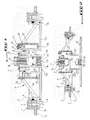
- Fig. 1 is a schematic cross-sectional elevation of the emptying device, object of the invention, illustrated in closed position.
- Fig. 2 is a sectional elevation, similar to FIG. 1, illustrating a modification.
- Fig. 3 is a schematic cross-sectional elevation similar to fig. 1 illustrating a modification.
- Fig. 4 is a sectional elevation illustrating a additional feature.
- the device illustrated in the drawing is intended to be mounted in a tank 1 at the bottom of it.
- the tank 1 is provided with a bead 2 bordering an opening 3 in which a base 4 is engaged.
- the base 4 delimits, at its periphery, a crown 5 comprising a sealing member 6, for example a ring toroid cooperating with the bead 2.
- the crown 5 is preferably provided with a sole 7 bearing against the underside of the bead 2, sole which is crossed by fixing screws 8 or other similar member.
- the base 4 has, in its center, a collar 9 which is connected to the crown 5 by oblique radial arms 10.
- the flange 9 has a central thread 11 in which is screwed a sleeve 12 projecting from a door 13 ensuring the closure of the base 4 against which said door 13 is supported.
- a sealing member consisting of at least one seal 14, is provided between the door 13 and the base, for example the sole 7 thereof.
- the seal between the door 13 and the base could be secured with the wall internal crown 5.
- the sleeve 12 has, in its wall, at least one notch of rupture 15 so as to constitute a breakable organ.
- the interior of the sleeve 12 contains a cartridge pyrotechnic 16 can be actuated by a striker 17 contained in an electromagnetic assembly 18 or the like tight connection which is fixed, for example screwed, in the sleeve 12.
- the sleeve 12 is, moreover, closed, at its lower part, by a plug 19 advantageously connected to the cartridge 16 by a spring 20.
- the collar 9 it is advantageous, as illustrated by drawing, make the collar 9 so that it has radial lugs 9a corresponding to lugs 21 of a shirt 22 provided with re-entrant radial tabs 23 which are fixed to said legs 9a, for example by screws 24.
- the jacket 22 is provided, in addition, at its part low, legs 25 also radial to form retaining stops for peripheral projections 26 of a bole 27 formed or attached to door 13 around the sleeve 12.
- the spacings between the radial legs 25, the projections peripherals 26, as well as between the legs 9a and the re-entrant radial legs 23 are provided so as to allow the fitting of the shirt 22 around the flange 9 then the installation of the screws 24, as well as the fitting of the shirt 22 around the barrel 27 before the fixing of said jacket 22 by screws 24.
- the door 13 has lights 28 between the barrel 27 and the sleeve 12. This creates a circuit for evacuating gases produced during cartridge operation pyrotechnic 16.
- the sleeve 12 is screwed into the collar 9 for example in acting on the plug 19 provided with a screwing cutout 29, for example a saw cut.
- seals 30 interposed between the flange 9 and bole 27.
- the electromagnetic assembly 18 is supplied so that the striker 17 initiates the pyrotechnic cartridge 16.
- the electromagnetic assembly 18 constitutes an insulating plug the pyrotechnic cartridge 16 from inside the tank and it's advantageous like illustrated, that seals 31 be placed between the collar 9 and said electromagnetic assembly 18.
- the triggering of the pyrotechnic cartridge 16 causes the rupture of the sleeve 12 of which the separate part including the plug 19 is ejected as well as door 13.
- the door 13 and its barrel 27 are moved and separated from the base 4 allowing the fuel to flow at outside by the very large openings left free by the base 4.
- the legs 25 of the shirt 22 and 26 of the barrel 27 constitute retainers when brought into contact to prevent the door 13 from being ejected completely.
- the door 13 must preferably be changed since the sleeve 12 is broken as illustrated in fig. 2. It can be done easily for example by turning door 13 to that the peripheral projections 26 are brought between radial lugs 25. Next, the ruptured part of the sleeve 12 can be removed by unscrewing it and a new door is then put in place.
- the sleeve 12 is removably attached to door 13 for example in screwing it into a sheath 12a. Such a provision allows to replace only the sleeve 12 and the cartridge pyrotechnic after use.
- means are provided damping between door 13 and jacket 22 to avoid a shock at the end of the door opening stroke 13.
- the above means may for example include rings 34 and 35, for example of flexible material, arranged in below the projections 26 and above the legs 25. A small space is provided between the rings and the walls of the was 27 on the one hand and the shirt 22 on the other hand. Of the so we produce a damping effect when opening the door.
- Fig. 3 illustrates a slight variant according to which sets up on the sleeve 12 a pyrotechnic assembly 32 of the waterproof type, that is to say not letting escape from gas during operation, this pyrotechnic assembly being provided with a piston 33 which is moved during actuation of said assembly to strike the breakable zone of the sleeve 12 by causing it to separate and ejecting the door 13 in the same manner as described above.
Landscapes
- Engineering & Computer Science (AREA)
- General Engineering & Computer Science (AREA)
- Aviation & Aerospace Engineering (AREA)
- Mechanical Engineering (AREA)
- Pressure Vessels And Lids Thereof (AREA)
Abstract
Description
Claims (11)
- Dispositif de vidange pour réservoirs de fluide en particulier de carburant en particulier pour aéronefs et analogues, caractérisé en ce qu'il comporte une embase (4) fixée à la paroi (1) du réservoir dans une ouverture de celui-ci, ladite embase supportant une collerette (9) par des bras radiaux (10), ladite collerette étant reliée par un organe sécable (15) à une porte (13) assurant la fermeture de l'embase (4) et un ensemble pyrotechnique (16) étant prévu pour provoquer la rupture de l'organe sécable.
- Dispositif suivant la revendication 1, caractérisé en ce que l'organe sécable est constitué par un manchon (12) présentant une encoche de rupture (15), ledit manchon étant fixé à la collerette (9) et supportant l'ensemble pyrotechnique (16, 32) actionné par un ensemble électromagnétique (18) étanche isolant l'intérieur du manchon (12) de l'intérieur du réservoir (1).
- Dispositif suivant l'une des revendications 1 et 2, caractérisé en ce que l'organe sécable constitué par le manchon (12) présentant l'encoche (15) est disposé à l'intérieur d'un fût (27) de la porte (13), fût mis en communication avec l'atmosphère par des lumières (28) pour constituer un circuit d'évacuation de gaz.
- Dispositif suivant l'une des revendications 1 et 2, caractérisé en ce que l'ensemble pyrotechnique (32) est du type étanche à piston d'actionnement (33).
- Dispositif suivant l'une des revendications 1 à 4, caractérisé en ce que l'ensemble pyrotechnique est constitué par une cartouche pyrotechnique (16) maintenue à l'intérieur du manchon (12) entre un bouchon de fermeture (19) dudit manchon et l'ensemble électromagnétique (18) relié à la collerette (9) de l'embase (4) par un joint (31).
- Dispositif suivant l'une des revendications 1 à 5, caractérisé en ce que l'embase (4) est fixée au réservoir (1) par une semelle (7) et des vis de fixation (8).
- Dispositif suivant la revendication 6, caractérisé en ce que la semelle (7) est formée à partir d'une couronne (5) reliée de façon étanche à un bourrelet (2) du réservoir (1).
- Dispositif suivant l'une des revendications 1 à 7, caractérisé en ce que la porte (13) est reliée par un fût (27) à des pattes (26) venant en butée contre des pattes radiales (25) d'une chemise (22) lors de l'ouverture de ladite porte (13).
- Dispositif suivant l'une des revendications 1 à 8, caractérisé en ce que la chemise (22) est fixée à la collerette (9) par des vis (24) vissées dans des pattes (9a) de ladite collerette (9).
- Dispositif suivant l'une des revendications 1 à 9, caractérisé en ce que le manchon (12) est rapporté par une douille (12a) à la porte (13).
- Dispositif suivant l'une des revendications 1 à 10 caractérisé par des moyens d'amortissement associés à la porte (13).
Applications Claiming Priority (2)
| Application Number | Priority Date | Filing Date | Title |
|---|---|---|---|
| FR9707583 | 1997-06-18 | ||
| FR9707583A FR2764862A1 (fr) | 1997-06-18 | 1997-06-18 | Dispositif de vidange pour reservoir de carburant |
Publications (1)
| Publication Number | Publication Date |
|---|---|
| EP0885804A1 true EP0885804A1 (fr) | 1998-12-23 |
Family
ID=9508131
Family Applications (1)
| Application Number | Title | Priority Date | Filing Date |
|---|---|---|---|
| EP98401460A Withdrawn EP0885804A1 (fr) | 1997-06-18 | 1998-06-15 | Dispositif de vidange pour réservoir de carburant |
Country Status (2)
| Country | Link |
|---|---|
| EP (1) | EP0885804A1 (fr) |
| FR (1) | FR2764862A1 (fr) |
Citations (5)
| Publication number | Priority date | Publication date | Assignee | Title |
|---|---|---|---|---|
| US3339800A (en) * | 1966-09-08 | 1967-09-05 | William H Sustrich | Method and apparatus for safe voiding of tanks filled with inflammable liquids or vapors |
| FR2058868A5 (fr) * | 1969-09-30 | 1971-05-28 | Etude Propulsion Reactio | |
| FR2321422A1 (fr) * | 1975-08-19 | 1977-03-18 | Alkan R & Cie | Dispositif dit " vide-vite " pour la vidange rapide d'un reservoir de combustible sur un avion |
| FR2350250A1 (fr) * | 1976-05-05 | 1977-12-02 | Const Aero Navales | Dispositif pour la vidange rapide de reservoirs |
| US4715448A (en) * | 1984-07-24 | 1987-12-29 | Mcculloch Alister L | Fire extinguisher outlet head |
-
1997
- 1997-06-18 FR FR9707583A patent/FR2764862A1/fr active Pending
-
1998
- 1998-06-15 EP EP98401460A patent/EP0885804A1/fr not_active Withdrawn
Patent Citations (5)
| Publication number | Priority date | Publication date | Assignee | Title |
|---|---|---|---|---|
| US3339800A (en) * | 1966-09-08 | 1967-09-05 | William H Sustrich | Method and apparatus for safe voiding of tanks filled with inflammable liquids or vapors |
| FR2058868A5 (fr) * | 1969-09-30 | 1971-05-28 | Etude Propulsion Reactio | |
| FR2321422A1 (fr) * | 1975-08-19 | 1977-03-18 | Alkan R & Cie | Dispositif dit " vide-vite " pour la vidange rapide d'un reservoir de combustible sur un avion |
| FR2350250A1 (fr) * | 1976-05-05 | 1977-12-02 | Const Aero Navales | Dispositif pour la vidange rapide de reservoirs |
| US4715448A (en) * | 1984-07-24 | 1987-12-29 | Mcculloch Alister L | Fire extinguisher outlet head |
Also Published As
| Publication number | Publication date |
|---|---|
| FR2764862A1 (fr) | 1998-12-24 |
Similar Documents
| Publication | Publication Date | Title |
|---|---|---|
| EP0342109B1 (fr) | Capsule à enveloppe tournante pour flacons et récipients analogues | |
| FR2517790A1 (fr) | Valve a levee equipee d'un soufflet entre l'obturateur et le corps, notamment pour fluides radioactifs ou toxiques | |
| FR2776633A1 (fr) | Dispositif de distribution airless | |
| CH386939A (fr) | Dispositif de fermeture étanche avec valve pour récipient distributeur de fluide | |
| FR2694612A1 (fr) | Ensemble piston-tige de piston d'un ressort à gaz de longueur réglable. | |
| EP0567374B1 (fr) | Capsule distributrice pour produits liquides ou pâteux | |
| EP3428741B1 (fr) | Soupape de securite pour montre | |
| FR2957626A1 (fr) | Actionneur d'ouverture d'urgence a gaz d'un ouvrant d'aeronef, comportant des moyens d'echappement du gaz | |
| EP0345102B1 (fr) | Bouchon de réservoir | |
| EP0583193A2 (fr) | Perfectionnement à l'assemblage d'une pompe dans un réservoir | |
| FR2631318A1 (fr) | Capsule a enveloppe tournante pour flacons et recipients analogues | |
| CH655375A5 (fr) | Valve pour le remplissage d'un recipient a gaz. | |
| FR2764862A1 (fr) | Dispositif de vidange pour reservoir de carburant | |
| EP0506564A1 (fr) | Applicateur pour liquide, sensible à la pression de contact | |
| FR2789053A1 (fr) | Bouchon universel pour la fermeture de bouteilles deja debouchees, en particulier pour les bouteilles de vin ou de mousseux | |
| FR2701529A1 (fr) | Soupapes de sûreté à membrane du type cartouche, de conception modulaire. | |
| FR2525991A1 (fr) | Bouchon visse pour recipients | |
| FR2500412A1 (fr) | Dispositif de fermeture de reservoir notamment de carburant | |
| EP1317636B1 (fr) | Robinet-detendeur a montage rapide sur une bouteille de gaz | |
| FR2896024A1 (fr) | Bouchon equipe d'un clapet de surpression | |
| FR2787092A1 (fr) | Bouchon a capsule verrouillable sur le goulot d'un recipient | |
| FR2642730A1 (fr) | Bouteille en materiau relativement elastiquement deformable a bouchon imperdable | |
| BE484125A (fr) | ||
| FR2630201A1 (fr) | Dispositif pour purger et vidanger un echangeur de chaleur | |
| FR2726064A1 (fr) | Dispositif de purge notamment pour un circuit de refroidissement de moteur de vehicule automobile |
Legal Events
| Date | Code | Title | Description |
|---|---|---|---|
| PUAI | Public reference made under article 153(3) epc to a published international application that has entered the european phase |
Free format text: ORIGINAL CODE: 0009012 |
|
| AK | Designated contracting states |
Kind code of ref document: A1 Designated state(s): AT BE CH CY DE DK ES FI FR GB GR IE IT LI LU MC NL PT SE |
|
| AX | Request for extension of the european patent |
Free format text: AL;LT;LV;MK;RO;SI |
|
| AKX | Designation fees paid | ||
| STAA | Information on the status of an ep patent application or granted ep patent |
Free format text: STATUS: THE APPLICATION IS DEEMED TO BE WITHDRAWN |
|
| 18D | Application deemed to be withdrawn |
Effective date: 19990624 |
|
| REG | Reference to a national code |
Ref country code: DE Ref legal event code: 8566 |
|
| RIN1 | Information on inventor provided before grant (corrected) |
Inventor name: MARTIN, CLAUDE Inventor name: REIS, JEAN-LUC ALBERT Inventor name: MABRU, THIERRY EDMOND SYLVESTRE |