EP0885989A2 - Broche de retordage à torsion multiple avec un pot rotatif limitant le ballon - Google Patents
Broche de retordage à torsion multiple avec un pot rotatif limitant le ballon Download PDFInfo
- Publication number
- EP0885989A2 EP0885989A2 EP98107106A EP98107106A EP0885989A2 EP 0885989 A2 EP0885989 A2 EP 0885989A2 EP 98107106 A EP98107106 A EP 98107106A EP 98107106 A EP98107106 A EP 98107106A EP 0885989 A2 EP0885989 A2 EP 0885989A2
- Authority
- EP
- European Patent Office
- Prior art keywords
- thread
- wire twisting
- turntable
- coil support
- twisting spindle
- Prior art date
- Legal status (The legal status is an assumption and is not a legal conclusion. Google has not performed a legal analysis and makes no representation as to the accuracy of the status listed.)
- Withdrawn
Links
Images


Classifications
-
- D—TEXTILES; PAPER
- D01—NATURAL OR MAN-MADE THREADS OR FIBRES; SPINNING
- D01H—SPINNING OR TWISTING
- D01H1/00—Spinning or twisting machines in which the product is wound-up continuously
- D01H1/14—Details
- D01H1/42—Guards or protectors for yarns or threads, e.g. separator plates, anti-ballooning devices
- D01H1/427—Anti-ballooning cylinders, e.g. for two-for-one twist machine
-
- D—TEXTILES; PAPER
- D01—NATURAL OR MAN-MADE THREADS OR FIBRES; SPINNING
- D01H—SPINNING OR TWISTING
- D01H7/00—Spinning or twisting arrangements
- D01H7/02—Spinning or twisting arrangements for imparting permanent twist
- D01H7/86—Multiple-twist arrangements, e.g. two-for-one twisting devices ; Threading of yarn; Devices in hollow spindles for imparting false twist
- D01H7/868—Yarn guiding means, e.g. guiding tubes
Definitions
- Double-wire twisting spindles come with a thread storage disc equipped, which serves between the radial exit of the thread from the spindle and take up a thread reserve from the thread balloon, which a constant thread tension and thus should also ensure an even thread.
- Thread storage by means of a thread storage disc can be described as an inertia-free thread brake.
- the proposed thread guide eyelet is a possible one Wrapping the balloon thread around the opposite direction to the Spindle rotor and balloon limiter rotating bobbin protection pot prevent.
- the space curve of the thread begins at Exit from the spindle rotor, and it ends either attached to the upper edge of the balloon and the thread guide eyelet through which the thread passes or in the absence of such a thread guide eyelet directly in the extension of the spindle axis lying balloon thread guide eyelet.
- the balloon thread may not be unique between the outlet opening from the spindle rotor in lower balloon limiter area and the thread guide eyelet is inserted in the upper balloon limiter area. Case by case can then as a result, especially in the arrival or Phase-out phase of the spindle, the balloon thread for Wrap around the counter-rotating bobbin protection pot tend. Now a "rewinding process" begins because the thread running from the supply spool is practical Enter unchecked into the area of the thread balloon can. This winding process can depend on the individual tensile strength of the thread or yarn up to Blockage of the counter rotating spindle parts progress.
- a blockage between the rotating spindle parts can occur especially when parts of the thread package from the cylindrical jacket of the coil carrier protective pot slide down and into the relative narrow gap between the top of the spindle rotor and enter the bottom of the bobbin.
- Such measures on double wire twisting spindles are however not for preventing a blockage causing winding formation on a triple wire twisting spindle suitable because in the case of a double-wire twisting spindle the starting position is always a rotating one Machine part to a standing machine part is while a blockage with a triple wire twist spindle causing wrap formation between two opposing rotating parts must be prevented.
- the invention has for its object in a Multi-wire twisting spindle with counter to the bobbin circumferential balloon limiter a measure to prevent of a blockage between the rotating ones Spindle parts causing thread infeed between to create the counter rotating spindle parts by the harmful winding process described above is quickly interrupted.
- the from the outer jacket of the coil support protective pot down Sliding thread packages are preferred by the groove-like Shaping of the thread catcher ring included in the also has the essential effect of a labyrinth ring.
- the amount of winding on the thread catcher can still be reduced in that the thread catch ring especially in the area of its thread catch groove Has thread or rope friction increasing surface.
- FIG. 1 shows a representative of a twisting machine Part of a spindle bank 1, in which a spindle bearing sleeve 2 is stationary.
- a spindle shaft 5 rotatable stored, at the lower end of one towards the Arrow f1 rotatably driven spindle whorl 6 attached is.
- the spindle shaft 5 joins the spindle hollow axis 7, at the bottom End one with a radial thread guide channel 9 provided turntable 8 is attached.
- Thread eyelet 10 which has an axially upward Deflecting channel 11.
- the turntable 8 closes an upwardly extending balloon restrictor 12, which in its upper area, preferably at the upper edge of the balloon, at an angular distance from the radial outlet opening the thread guide channel 9 and the deflection channel 11 a thread guide eyelet 13 wears.
- the lower balloon delimiter edge completed by an annular body 14 down.
- a sleeve-shaped coil carrier hub 21 rotatably supported, which has a coil carrier base 22 at its lower end has a coil holder protective pot on its outer circumference 25 carries.
- the driver magnets 18 opposite Counter magnets 18.1 attached which, based on the driving magnets 18, are polarized such that when rotating Coil carrier whorl 17 also from coil carrier hub 21, Coil carrier base 22 and protective pot 25 existing coil carrier is driven in the same direction of rotation.
- In the upper end of the coil carrier hub 21 is concentric a thread inlet tube 23 to the spindle hollow axis 7 used.
- On the bobbin hub 21 is a supply bobbin 24 so pushed and on the bobbin bottom 22 turned off that the supply spool 24 with rotating bobbin 21, 22 also slip-free is rotated.
- the thread F is lifted upwards from the Supply spool 23 is pulled off and through the thread inlet tube 23 and the spindle hollow axis 7 first below and then through the radial thread guide channel 9 outwards and then again between the coil carrier protection pot 25 and the balloon limiter 12 upwards to one lying in the extension of the hollow spindle axis Thread guide eyelet 26, from where the thread then leads to one Winding unit, not shown, runs.
- the thread is passed through the thread guide eyelet 13, the at an appropriate angular distance, preferably 20 ° to 120 °, from the exit opening of the radial directed thread guide channel 9 or the thread deflecting channel 11 lies.
- the invention consists in a in the area of the radially outer Area of the coil support base 22 below and with an axial Distance from it arranged thread catcher ring 8.1, which to the Connects top of the turntable 8 and together with this and the balloon limiter 12 rotates.
- This thread catcher ring 8.1 is formed in one piece with the turntable 8 and extends axially against the underside of the coil support base 22.
- the outer diameter of this ring section 8.1 is smaller than the outside diameter of the coil carrier base 22 and the coil support protective pot 25.
- a labyrinth seal preferably in one on the bottom of the coil carrier base 22 located annular groove 22.1 projecting ring section 8.1 points to the formation of a thread collecting groove 8.2 on its outer circumference one inside and one behind undercut directed below.
- the thread catcher 8.1 has 8.2 in particular in the area of the thread receiving groove a surface increasing the thread or rope friction.
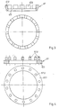
- the thread catch ring 27 shown in FIG. 2 is as a separate organ in a receptacle on the top the turntable 8 used and is preferably from a material that increases the thread or rope friction.
- the ring 27 has an inward and downward undercut on that adjacent to the turntable 8 a Thread catch groove 27.1 forms.
- FIG. 3 shows one preferably in a receptacle Turntable 8 insert thread ring 47, consisting of an annular body 47.1 with adjoining segment pieces 47.2.
- the thread catch ring 57 consists of an annular body 57.1 with pins inserted therein 57.2.
- the advantages Both versions are also in a better air circulation to see a contribution to lower pollution the inner rotating spindle parts.
- existing thread packages can be created by the resulting Gaps between the segments or pins better removed will.
- Particularly advantageous for the better function of the thread catch ring has the height difference "X" between the Lower edge of the coil support protection pot 25 and the outlet opening of the thread channel 11 shown. So the lower one should Edge of the coil carrier protection pot definitely higher lie than the outlet opening of the thread guide channel 11 on rotating balloon limiter.
Landscapes
- Engineering & Computer Science (AREA)
- Mechanical Engineering (AREA)
- Textile Engineering (AREA)
- Spinning Or Twisting Of Yarns (AREA)
- Guides For Winding Or Rewinding, Or Guides For Filamentary Materials (AREA)
Applications Claiming Priority (2)
| Application Number | Priority Date | Filing Date | Title |
|---|---|---|---|
| DE19726450 | 1997-06-21 | ||
| DE19726450A DE19726450C1 (de) | 1997-06-21 | 1997-06-21 | Mehrfachdraht-Zwirnspindel mit rotierendem Ballonbegrenzer |
Publications (2)
| Publication Number | Publication Date |
|---|---|
| EP0885989A2 true EP0885989A2 (fr) | 1998-12-23 |
| EP0885989A3 EP0885989A3 (fr) | 2000-02-23 |
Family
ID=7833283
Family Applications (1)
| Application Number | Title | Priority Date | Filing Date |
|---|---|---|---|
| EP98107106A Withdrawn EP0885989A3 (fr) | 1997-06-21 | 1998-04-18 | Broche de retordage à torsion multiple avec un pot rotatif limitant le ballon |
Country Status (6)
| Country | Link |
|---|---|
| US (1) | US5979154A (fr) |
| EP (1) | EP0885989A3 (fr) |
| CN (1) | CN1203287A (fr) |
| CZ (1) | CZ195898A3 (fr) |
| DE (1) | DE19726450C1 (fr) |
| TR (1) | TR199801159A3 (fr) |
Families Citing this family (8)
| Publication number | Priority date | Publication date | Assignee | Title |
|---|---|---|---|---|
| DE19817314C2 (de) * | 1998-04-18 | 2000-11-30 | Volkmann Gmbh & Co | Spindel, insbesondere Dreifachdraht-Zwirnspindel |
| DE19817315C1 (de) * | 1998-04-18 | 1999-06-02 | Volkmann Gmbh & Co | Spindel |
| US20030140468A1 (en) * | 2002-01-28 | 2003-07-31 | Shaikh Humayan N. | Twist after dyeing method of processing yarn |
| DE102010013795A1 (de) * | 2010-04-03 | 2011-10-06 | Oerlikon Textile Gmbh & Co. Kg | Doppeldraht-Zwirnspindel |
| CN102154746A (zh) * | 2010-12-14 | 2011-08-17 | 江苏华佳丝绸有限公司 | 一种倍捻机锭子轴承保护装置 |
| TR201606346A2 (tr) | 2016-05-13 | 2017-01-23 | Sanko Tekstil Isletmeleri Sanayi Ve Ticaret Anonim Sirketi | Balon çapının kontrol edilmesini sağlayan aparat |
| WO2019214538A1 (fr) * | 2018-05-07 | 2019-11-14 | 屏山红彤彤纺织有限公司 | Broche à torsion multiple et retordeuse à double torsion |
| KR101978897B1 (ko) * | 2018-07-19 | 2019-09-03 | 조용 | 커버링사의 제조장치 |
Family Cites Families (6)
| Publication number | Priority date | Publication date | Assignee | Title |
|---|---|---|---|---|
| DE1510836A1 (de) * | 1951-01-28 | 1970-03-12 | Palitex Project Co Gmbh | Doppeldrahtzwirnmaschine mit ein- oder beiderseitiger Spindelbestueckung |
| CH464749A (it) * | 1967-08-28 | 1968-10-31 | Ratti Spa Michele | Fuso a doppia torsione a grande diametro |
| US3636698A (en) * | 1968-06-08 | 1972-01-25 | Murata Machinery Ltd | Method of threading a two-for-one yarn twister |
| DE2830265C2 (de) * | 1978-07-10 | 1983-01-13 | Palitex Project-Company Gmbh, 4150 Krefeld | Doppeldraht-Zwirnspindel |
| DE2939645C2 (de) * | 1979-09-29 | 1982-10-14 | Palitex Project-Company Gmbh, 4150 Krefeld | Stator für eine Doppeldraht-Spinn- oder- Zwirnspindel |
| DE4307685C1 (de) * | 1993-03-11 | 1994-11-17 | Hamel Ag | Verfahren zum Aufbau einer Fadenreserve an einem rotierenden Ballonbegrenzer einer Mehrfachdraht-Zwirnspindel und Mehrfachdraht-Zwirnspindel mit rotierendem Ballonbegrenzer |
-
1997
- 1997-06-21 DE DE19726450A patent/DE19726450C1/de not_active Expired - Fee Related
-
1998
- 1998-04-18 EP EP98107106A patent/EP0885989A3/fr not_active Withdrawn
- 1998-06-19 US US09/100,213 patent/US5979154A/en not_active Expired - Fee Related
- 1998-06-19 CN CN98114923A patent/CN1203287A/zh active Pending
- 1998-06-19 TR TR1998/01159A patent/TR199801159A3/tr unknown
- 1998-06-19 CZ CZ981958A patent/CZ195898A3/cs unknown
Also Published As
| Publication number | Publication date |
|---|---|
| CZ195898A3 (cs) | 1999-01-13 |
| US5979154A (en) | 1999-11-09 |
| TR199801159A2 (xx) | 1999-10-21 |
| DE19726450C1 (de) | 1998-07-02 |
| EP0885989A3 (fr) | 2000-02-23 |
| TR199801159A3 (tr) | 1999-10-21 |
| CN1203287A (zh) | 1998-12-30 |
Similar Documents
| Publication | Publication Date | Title |
|---|---|---|
| EP2371999B1 (fr) | Bobine de câblage ou broche de métier à retordre à double fil | |
| DE2315392A1 (de) | Fadenhandhabungsvorrichtung | |
| DE19726450C1 (de) | Mehrfachdraht-Zwirnspindel mit rotierendem Ballonbegrenzer | |
| EP1101847B1 (fr) | Cableuse et broche à retordre à double torsion avec dispositif d'enfilage pneumatique | |
| EP0615010B1 (fr) | Procédé pour l'obtention d'une réserve de fil déterminée dans un limiteur de ballon tournant d'une broche à torsion multiple et broche à torsion multiple avec limiteur de ballon tournant | |
| DE3130615A1 (de) | "fadenfuehrungsvorrichtung" | |
| DE3916969A1 (de) | Fadenfuehrungsvorrichtung fuer eine doppeldrahtzwirnmaschine | |
| DE2831506C2 (fr) | ||
| DE3015044A1 (de) | Doppeldrahtzwirneinrichtung | |
| DE2544689C3 (de) | Spindel für Ringspinn- und Ringzwirnmaschinen, insbesondere für Cordzwirnmaschinen | |
| DE69026325T2 (de) | Doppeldrahtzwirnmaschinen mit einer Spindel aus zwei Hohlwellen und mit einer beweglichen Wellenkupplung | |
| EP0458088B1 (fr) | Dispositif de sectionnement pour une broche d'un métier à filer ou à retordre | |
| DE3310438A1 (de) | In ihrer geometrischen form veraenderbare ablaufhilfe fuer den ueberkopf-abzug eines fadens von einer vorlagespule | |
| DE2939702A1 (de) | Doppeldraht-spinn- oder -zwirnspindel mit druckluftbetaetigter einfaedelvorrichtung | |
| EP1361301A2 (fr) | Bobine de câblage et utilisation d'un guide-fil ou oeillet de centrage à enfilage automatique au niveau du boítier de protection d'une bobine de câblage | |
| DE3330523C1 (de) | Doppeldraht-Zwirnspindel | |
| DE19755824C2 (de) | Doppeldrahtzwirnspindel zum Verdrehen von Naturseide | |
| DE2919100C2 (de) | Einrichtung zum Umwinden eines elastischen Kernfadens | |
| DE3732904C1 (de) | Doppeldraht-Zwirnspindel | |
| DE2415167A1 (de) | Wickellegevorrichtung zur herstellung von kernlosen wickeln aus schlaufenfoermig in ringbahnen abgelegtem fadenmaterial | |
| EP0887446A2 (fr) | Procédé et broche de retordage d'un fil triple pour assemblage et retordage simultanés | |
| DE2320577A1 (de) | Doppeldrahtspindel zum zwirnen und fachen von faeden | |
| DE19817314C2 (de) | Spindel, insbesondere Dreifachdraht-Zwirnspindel | |
| DE1086158B (de) | Doppeldrahtzwirnspindel, insbesondere fuer schwere Zwirne, mit durch Magnete gehaltenem Spulentraegerkoerper | |
| DE4010016C2 (fr) |
Legal Events
| Date | Code | Title | Description |
|---|---|---|---|
| PUAI | Public reference made under article 153(3) epc to a published international application that has entered the european phase |
Free format text: ORIGINAL CODE: 0009012 |
|
| AK | Designated contracting states |
Kind code of ref document: A2 Designated state(s): CH FR GB IT LI |
|
| AX | Request for extension of the european patent |
Free format text: AL;LT;LV;MK;RO;SI |
|
| PUAL | Search report despatched |
Free format text: ORIGINAL CODE: 0009013 |
|
| AK | Designated contracting states |
Kind code of ref document: A3 Designated state(s): AT BE CH CY DE DK ES FI FR GB GR IE IT LI LU MC NL PT SE |
|
| AX | Request for extension of the european patent |
Free format text: AL;LT;LV;MK;RO;SI |
|
| 17P | Request for examination filed |
Effective date: 20000816 |
|
| AKX | Designation fees paid |
Free format text: CH FR GB IT LI |
|
| GRAH | Despatch of communication of intention to grant a patent |
Free format text: ORIGINAL CODE: EPIDOS IGRA |
|
| STAA | Information on the status of an ep patent application or granted ep patent |
Free format text: STATUS: THE APPLICATION HAS BEEN WITHDRAWN |
|
| 18W | Application withdrawn |
Effective date: 20030211 |
|
| REG | Reference to a national code |
Ref country code: DE Ref legal event code: 8566 |