EP0886106A1 - Steuereinrichtung für Gasbrenner - Google Patents
Steuereinrichtung für Gasbrenner Download PDFInfo
- Publication number
- EP0886106A1 EP0886106A1 EP98110659A EP98110659A EP0886106A1 EP 0886106 A1 EP0886106 A1 EP 0886106A1 EP 98110659 A EP98110659 A EP 98110659A EP 98110659 A EP98110659 A EP 98110659A EP 0886106 A1 EP0886106 A1 EP 0886106A1
- Authority
- EP
- European Patent Office
- Prior art keywords
- control device
- gas
- rod
- time
- gas supply
- Prior art date
- Legal status (The legal status is an assumption and is not a legal conclusion. Google has not performed a legal analysis and makes no representation as to the accuracy of the status listed.)
- Ceased
Links
Images


Classifications
-
- F—MECHANICAL ENGINEERING; LIGHTING; HEATING; WEAPONS; BLASTING
- F23—COMBUSTION APPARATUS; COMBUSTION PROCESSES
- F23N—REGULATING OR CONTROLLING COMBUSTION
- F23N5/00—Systems for controlling combustion
- F23N5/02—Systems for controlling combustion using devices responsive to thermal changes or to thermal expansion of a medium
- F23N5/10—Systems for controlling combustion using devices responsive to thermal changes or to thermal expansion of a medium using thermocouples
- F23N5/102—Systems for controlling combustion using devices responsive to thermal changes or to thermal expansion of a medium using thermocouples using electronic means
-
- F—MECHANICAL ENGINEERING; LIGHTING; HEATING; WEAPONS; BLASTING
- F23—COMBUSTION APPARATUS; COMBUSTION PROCESSES
- F23N—REGULATING OR CONTROLLING COMBUSTION
- F23N2223/00—Signal processing; Details thereof
- F23N2223/22—Timing network
-
- F—MECHANICAL ENGINEERING; LIGHTING; HEATING; WEAPONS; BLASTING
- F23—COMBUSTION APPARATUS; COMBUSTION PROCESSES
- F23N—REGULATING OR CONTROLLING COMBUSTION
- F23N2229/00—Flame sensors
- F23N2229/06—Flame sensors with periodical shutters; Modulation signals
-
- F—MECHANICAL ENGINEERING; LIGHTING; HEATING; WEAPONS; BLASTING
- F23—COMBUSTION APPARATUS; COMBUSTION PROCESSES
- F23N—REGULATING OR CONTROLLING COMBUSTION
- F23N2241/00—Applications
- F23N2241/08—Household apparatus
-
- F—MECHANICAL ENGINEERING; LIGHTING; HEATING; WEAPONS; BLASTING
- F23—COMBUSTION APPARATUS; COMBUSTION PROCESSES
- F23N—REGULATING OR CONTROLLING COMBUSTION
- F23N5/00—Systems for controlling combustion
- F23N5/02—Systems for controlling combustion using devices responsive to thermal changes or to thermal expansion of a medium
- F23N5/04—Systems for controlling combustion using devices responsive to thermal changes or to thermal expansion of a medium using bimetallic elements
-
- F—MECHANICAL ENGINEERING; LIGHTING; HEATING; WEAPONS; BLASTING
- F23—COMBUSTION APPARATUS; COMBUSTION PROCESSES
- F23N—REGULATING OR CONTROLLING COMBUSTION
- F23N5/00—Systems for controlling combustion
- F23N5/02—Systems for controlling combustion using devices responsive to thermal changes or to thermal expansion of a medium
- F23N5/06—Systems for controlling combustion using devices responsive to thermal changes or to thermal expansion of a medium using bellows; using diaphragms
-
- F—MECHANICAL ENGINEERING; LIGHTING; HEATING; WEAPONS; BLASTING
- F23—COMBUSTION APPARATUS; COMBUSTION PROCESSES
- F23N—REGULATING OR CONTROLLING COMBUSTION
- F23N5/00—Systems for controlling combustion
- F23N5/20—Systems for controlling combustion with a time program acting through electrical means, e.g. using time-delay relays
Definitions
- the invention relates to a control device for a gas burner, with a gas valve for the gas supply to the gas burner and a flame monitoring device, which is operatively connected to the gas valve.
- gas cookers are usually used with mechanical Gas control devices used gas control blocks, the flow of the Control the gas to the flame outlet opening of the gas burner.
- Bimetal sensor attached to inflame to be able to measure the gas.
- the user must now have an actuator for so long hold down until the bimetal reaches a predetermined temperature Has. Then the gas flame burns even without holding down the actuator continue. If the gas flame fails for any reason, so the bimetal probe cools down and closes the gas supply via a mechanism in the gas control block. This prevents unburned gas from escaping.
- DE 34 21 039 C2 discloses a control device for a gas burner an igniter for igniting gas and with a gas valve which controls the gas supply influenced to a burner.
- a flame monitoring device is used to keep it open of the gas valve as long as the gas burns. To reignite the gas
- To enable a controllable switch has been used by the flame monitoring device is controlled and closes while the gas burns. Of the controllable switch remains for a certain time after the flame goes out closed.
- the desired system expansion is essentially that the on your Escaping gas flame can be controlled time-controlled.
- the time is controlled by a stove timer, whereby here in particular advantageous embodiment, a radio-controlled stove timer can be used can.
- a gas valve be placed in front of a control block which, when a set time has elapsed the gas supply closes. This will extinguish the flame at the outlet on Gas burner.
- a bimetal control can be used, which indirectly as Locking mechanism is used.
- the bimetal control can be an electro-mechanical one Relay or an electro-hydraulic relay affect which a contact plunger or a contact piston in the line or between that introduces second-controlled expansion element of a temperature sensor.
- the Time control is now the moving out of the contact plunger or Contact piston causes. This will eventually become the lead of the temperature sensor relieved again and thereby actuating the gas supply closing mechanism, so that the temperature sensor simulates an insufficient temperature and the Gas control block finally closes the gas supply.
- Another option for time-controlled control of the gas flame is in placing an aperture between the gas flame and the temperature sensor. This cools the temperature sensor and closes the gas supply via the Gas control block.
- FIG. 1 shows a main gas supply line 1, into which a gas control block 2 is inserted is.
- lines 3 go from the gas control block 2 to temperature sensors.
- two gas lines 5 are branched, the Flame outlet openings 6 end near the temperature sensors 4.
- a gas valve 7 with control lines 8 drove in the main gas supply line 1 Connection to a timing device 11.
- the direction of flow of the gas is identified by arrow 9.
- this gas control device controls the flow of the gas.
- the gas sensors 4 are attached, which are usually designed as bimetal sensors.
- the user must now hold an actuator or a gag or other for as long Depress the mechanical element until a predetermined one is reached on the bimetal sensor Temperature is present. Then the user can cancel the operation because now if the flame is burning, the gas supply is automatically secured via the gas control blocks remains. However, if the flame fails, the temperature sensor cools down and closes the gas supply via a built-in locking mechanism. Then that is prevents the escape of unburned gas.
- the gas valve 7 used in the main gas supply line 1 with the control lines 8 is connected to a timer 10.
- this time control device 10 there is a clock, for example a radio-controlled or a quartz-controlled one Herduhruhr 11.
- input buttons 12 for entering a start date and 13 are provided for entering a deadline. So the user can determine when the gas valve is opened and a Inflammation of the gas at a certain hotplate or gas outlet nozzle takes place. For this purpose, it is determined by entering the end date at the same time which time the gas valve 7 closes and thus interrupts the gas supply. If the gas supply is interrupted, the flame will go out.
- control device 10 When entering a start date in the time control device 10 must of course Be sure that the gas ignites automatically at the consumer point takes place. To do this, an ignition device would have to be opened before for example, a spark ignition or a glow starter. In this case, however, the ignition must be measured after 10 seconds be determinable. After this time the system automatically locks again and the gas supply is closed.
- the time control namely the start date and end date
- the time control can be controlled by interrupting the flame detection electronics. For example will close detection electronics for the start date and switch on the mains voltage (reset process); when the deadline is reached the detection electronics will interrupt the gas supply.
- a temperature sensor can be inserted into line 3 4 a bimetal-controlled and acted upon by the time control device 11
- Relay device 14 can be installed.
- the connection can be made using a threaded or bayonet connection 16 take place.
- the pipe 3 On the opposite side of the housing to the pipe section 15 is the pipe 3, which is also by a thread or Bayonet connection 16 is tightly connected to the housing 14.
- lead two electrical lines 17 for the positive pole and 18 for the negative pole a coil 19 of a relay 20 or 21 inserted in the housing 14
- Control lines 17, 18 are the electrical connection to the timing device 10 manufactured.
- the bimetal control device 14 according to FIG. 2 is an electro-mechanical one Relay 20 trained.
- a rod 22 is enclosed by a coil 19.
- On his one end of the rod 22 has a contact plunger 23, which according to the double arrow 24 is axially movable.
- the contact plunger 24 is thereby in line 3 of the temperature sensor 4 can be switched on.
- the electro-hydraulic relay 21 is essentially the same as the electro-mechanical Relay 20 built.
- the electro-hydraulic system is located is a piston 28, which in the opposite liquid lines 29th and 30 moves.
- the piston shaft 31 is in turn wrapped by a coil 19.
- a pressure on the tip of the temperature sensor 4 is transmitted via the Liquid columns in the lines 29 and 30, which continues in the housing 14. This pressure opens a gas supply line in control block 2. Should the Gas supply to be closed is timed and according to the expired Appointment withdrawn via the coil 19 of the piston 28, whereby the Pressure in the direction of arrow 32 is lifted slightly. This pressure release is sufficient again to close the valve in control block 2 for the gas supply. This also results in a negative linear expansion of the temperature sensor 4 manipulated.
- the position of the contact plunger 24 moved in means one Function of the bimetal sensor as without relay. This means that when the bimetal temperature is reached the impact of the user is canceled, and the gas supply remains intact. The timer then pulls out the Tappet 24 or hammer, causing an insufficient temperature is simulated for the temperature sensor 4. The gas control block 2 then closes the gas supply.
Landscapes
- Engineering & Computer Science (AREA)
- Chemical & Material Sciences (AREA)
- Combustion & Propulsion (AREA)
- Mechanical Engineering (AREA)
- General Engineering & Computer Science (AREA)
- Control Of Combustion (AREA)
Abstract
Description
- Figur 1
- Gaszufuhrleitungen und Temperaturfühler in vereinfachter schematischer Darstellung,
- Figur 1A
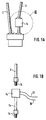
- die Einzelheit II in Figur 1 in vergrößerter Darstellung,
- Figur 1B
- die Einzelheit III in Figur 1A in vergrößerter Darstellung,
- Figur 2
- eine Steuereinrichtung in der Leitung eines Temperaturfühlers im Schnitt,
- Figur 3
- eine Steuereinrichtung anderer Bauart in der Leitung eines Temperaturfühlers im Schnitt.
Claims (11)
- Steuereinrichtung für einen Gasbrenner, insbesondere für Gaskochherde, mit einem Gasventil für die Steuerung der Gaszufuhr zu dem Gasbrenner und einer Flammenüberwachungseinrichtung, die mit dem Gasventil in Wirkverbindung steht,
dadurch gekennzeichnet,
daß die Flammenüberwachungseinrichtung eine Zeitsteuereinrichtung (11) aufweist, die entsprechend einer vorgegebenen Einschaltzeit und/oder Ausschaltzeit den Schließmechanismus des Gasventils (7) oder eines Gassteuerblocks (2) regelt. - Steuereinrichtung nach Anspruch 1,
dadurch gekennzeichnet,
daß das Gasventil (7) in der Gaszufuhrleitung (1) vor dem Gassteuerblock (2) angeordnet ist. - Steuereinrichtung nach Anspruch 1 oder 2,
dadurch gekennzeichnet,
daß die Zeitsteuereinrichtung (11) eine Uhr, insbesondere eine Herdschalt uhr, und insbesondere eine funkgesteuerte Herdschaltuhr ist. - Steuereinrichtung nach Anspruch 1,
dadurch gekennzeichnet,
daß die Zeitsteuereinrichtung mit einer Bimetall-Steuereinrichtung der Flammenüberwachungseinrichtung wirkverbunden ist, die ihrerseits mit dem Schließmechanismus des Gasventils und/oder des Steuerblocks (2) in Wirkverbindung steht. - Steuereinrichtung nach Anspruch 1 oder 4,
dadurch gekennzeichnet,
daß die Bimetall-Steuereinrichtung mit einem Sensor am oder nahe am Flammenaustritt des Gasbrenners (9) ausgerüstet ist und ein Ausdehnungselement (3,25,27,29,30) aufweist, in das die Zeitsteuereinrichtung (11) eingreift. - Steuereinrichtung nach einem der Ansprüche 1, 4 oder 5,
dadurch gekennzeichnet,
daß die Zeitsteuereinrichtung (11) ein elektromechanisches Relais (20) ansteuert, welches einen Kontaktstößel (Hammer 23) aufweist, der in die Bewegungsbahn des Ausdehlungselementes (3,25,27,29,30) bewegbar ist, und dessen Schaft mit der Zeitsteuereinrichtung (11) für das Schließen der Gaszuführ in Wirkverbindung steht. - Steuereinrichtung nach einem der vorgenannten Ansprüche,
dadurch gekennzeichnet,
daß die Zeitsteuereinrichtung (11) ein elektro-hydraulisches Relais (21) aufweist, welches einen Kontaktkolben (28) aufweist, der in die Bewegungsbahn des Ausdehnungselementes (3,25,27,29,30) bewegbar ist, dessen Kolbenschaft mit der Zeitsteuereinrichtung (11) für das Schließen der Gaszuführ wirkverbunden ist. - Steuereinrichtung nach einem der vorgenannten Ansprüche,
dadurch gekennzeichnet,
daß zwischen dem Temperaturfühler und der Gasflammenaustrittsöffnung des Gasbrenners eine den Sensor des Temperaturfühlers (4) beeinflussende Blende einschiebbar ist. - Steuereinrichtung nach einem der vorgenannten Ansprüche,
dadurch gekennzeichnet,
daß das Ausdehnungselement eine Stange, ein Stab oder dergleichen (25,27) ist, die in einen oberen Teil (25) der Stange und einen davon getrennten unteren Teil (27) der Stange aufgeteilt ist, wobei zwischen die einander gegenüberliegenden axialen Stirnflächen der Teile (25,27) der Stange der Kontaktstößel (23) einsetzbar ist. - Steuereinrichtung nach Anspruch 9,
dadurch gekennzeichnet,
daß der Kontaktkstößel (23) im wesentlichen keilförmig oder kegelförmig ausgebildet ist und mit seiner Mantelfläche mit den zugeordneten und entsprechend geformten Stirnflächen der Stange (25,27) in Wirkverbindung steht. - Steuereinrichtung nach einem der vorgenannten Ansprüche,
dadurch gekennzeichnet,
daß das Ausdehnungselement eine Flüssigkeit (29,30) ist, die säulenartig in Rohrleitungen eingesetzt ist, wobei die Flüssigkeitssäule durch einen quer zur Säulenlängsachse bewegbaren Kontaktkolben (28) in der Längenausdehnung beeinflußbar ist.
Applications Claiming Priority (2)
| Application Number | Priority Date | Filing Date | Title |
|---|---|---|---|
| DE19725921 | 1997-06-19 | ||
| DE19725921A DE19725921A1 (de) | 1997-06-19 | 1997-06-19 | Steuereinrichtung für Gasbrenner |
Publications (1)
| Publication Number | Publication Date |
|---|---|
| EP0886106A1 true EP0886106A1 (de) | 1998-12-23 |
Family
ID=7832940
Family Applications (1)
| Application Number | Title | Priority Date | Filing Date |
|---|---|---|---|
| EP98110659A Ceased EP0886106A1 (de) | 1997-06-19 | 1998-06-10 | Steuereinrichtung für Gasbrenner |
Country Status (3)
| Country | Link |
|---|---|
| US (1) | US6050808A (de) |
| EP (1) | EP0886106A1 (de) |
| DE (1) | DE19725921A1 (de) |
Families Citing this family (12)
| Publication number | Priority date | Publication date | Assignee | Title |
|---|---|---|---|---|
| DE10117899A1 (de) * | 2001-02-10 | 2002-08-14 | Gerd Lenzen | Verfahren zum Überwachen eines Gasstromes |
| US6572365B1 (en) * | 2002-03-26 | 2003-06-03 | Justin Byxbe | Automatic candle snuffer |
| KR100398650B1 (en) * | 2002-10-11 | 2003-09-19 | Jin Ha Park | Electronic safety apparatus of gas oven and gas oven therewith |
| DE502004010528D1 (de) * | 2003-09-25 | 2010-01-28 | Bsh Bosch Siemens Hausgeraete | Gaskochstelle |
| US7264222B2 (en) * | 2004-04-13 | 2007-09-04 | Burner Systems International, Inc. | Modular valve assembly |
| US20070031769A1 (en) * | 2005-08-05 | 2007-02-08 | David Burton | Automatic candle snuffer |
| US20070184395A1 (en) * | 2005-12-31 | 2007-08-09 | Taylor James M | Apparatuses and methods for automatically extinguishing a flame |
| DE102006054869B3 (de) * | 2006-11-20 | 2008-07-24 | Eurocopter Deutschland Gmbh | Verfahren zur Herstellung eines Halte-und Übersetzungsrahmens für einen gestapelten Piezoaktuator und elektrostriktiver Antrieb mit einem solchen Rahmen |
| US8065998B2 (en) * | 2008-03-24 | 2011-11-29 | Itw Food Equipment Group Llc | Cooking griddle and associated gas flow control arrangement |
| US20090242546A1 (en) * | 2008-03-26 | 2009-10-01 | Yungbluth Christian M | Cooking apparatus with thermally shielded temperature sensor |
| ES2430939R1 (es) * | 2012-05-22 | 2014-03-03 | BSH Electrodomésticos España S.A. | Aparato de cocción calentado a gas |
| RU2631403C1 (ru) * | 2016-05-25 | 2017-09-21 | Алексей Алексеевич Сердюков | Датчик температуры универсальный |
Citations (9)
| Publication number | Priority date | Publication date | Assignee | Title |
|---|---|---|---|---|
| GB297917A (en) * | 1927-08-02 | 1928-10-04 | Radiation Ltd | Improvements relating to thermostatically controlled gas valves |
| US1945109A (en) * | 1929-04-05 | 1934-01-30 | Wilcolator Co | Automatic fuel control device |
| GB1038141A (en) * | 1962-02-08 | 1966-08-10 | Marius Clement Carbonaro | Gas valve assembly |
| JPS55852A (en) * | 1978-06-19 | 1980-01-07 | Taada:Kk | Heating cooking instrument |
| JPS5685634A (en) * | 1979-12-12 | 1981-07-11 | Hitachi Heating Appliance Co Ltd | Gas quantity control device for gas burner |
| DE3421039C2 (de) | 1983-06-07 | 1986-04-10 | Asko OY, Lahti | Steuereinrichtung für einen Gasbrenner |
| GB2196150A (en) * | 1986-09-22 | 1988-04-20 | Sum Pang | Gas burner control |
| FR2624260A1 (fr) * | 1987-12-07 | 1989-06-09 | Elettro Termica Sud Spa | Appareil de chauffage a gaz |
| EP0686811A2 (de) * | 1994-05-12 | 1995-12-13 | MERLONI ELETTRODOMESTICI S.p.A. | Einrichtung zur Programmierung für ein Hausholtgaskochgerät |
Family Cites Families (11)
| Publication number | Priority date | Publication date | Assignee | Title |
|---|---|---|---|---|
| US2735484A (en) * | 1956-02-21 | Automatic ignition and control mechanism for gaseous fuel burners | ||
| US2302624A (en) * | 1940-02-05 | 1942-11-17 | Int Register Co | Burner control apparatus |
| US2303672A (en) * | 1940-05-31 | 1942-12-01 | Milwaukee Gas Specialty Co | Burner control apparatus |
| US2353042A (en) * | 1941-02-10 | 1944-07-04 | Honeywell Regulator Co | Temperature control system |
| US2363073A (en) * | 1942-01-19 | 1944-11-21 | Milwaukee Gas Specialty Co | Valve structure |
| US2562536A (en) * | 1949-07-29 | 1951-07-31 | Tappan Stove Co | Oven control |
| US2610682A (en) * | 1950-11-15 | 1952-09-16 | Robertshaw Fulton Controls Co | Control system for fluid fuel burners |
| US2711216A (en) * | 1951-06-05 | 1955-06-21 | Robertshaw Fulton Controls Co | Control system for fluid fuel burners |
| DE1874177U (de) * | 1959-11-12 | 1963-06-20 | Coleman Heizautomaten G M B H | Regelvorrichtung fuer oelheizoefen. |
| DE1835495U (de) * | 1960-10-12 | 1961-07-27 | Robert Zapp Hilden K G Maschf | Automatische oelbrennerschaltung mit zeitschaltuhr. |
| DE4133660A1 (de) * | 1991-10-11 | 1993-04-22 | Seppelfricke Geb Gmbh | Verfahren und vorrichtung zum regeln eines gasbrenners insbesondere bei gasbeheizten glaskeramikkochfeldern |
-
1997
- 1997-06-19 DE DE19725921A patent/DE19725921A1/de not_active Withdrawn
-
1998
- 1998-06-01 US US09/088,599 patent/US6050808A/en not_active Expired - Fee Related
- 1998-06-10 EP EP98110659A patent/EP0886106A1/de not_active Ceased
Patent Citations (9)
| Publication number | Priority date | Publication date | Assignee | Title |
|---|---|---|---|---|
| GB297917A (en) * | 1927-08-02 | 1928-10-04 | Radiation Ltd | Improvements relating to thermostatically controlled gas valves |
| US1945109A (en) * | 1929-04-05 | 1934-01-30 | Wilcolator Co | Automatic fuel control device |
| GB1038141A (en) * | 1962-02-08 | 1966-08-10 | Marius Clement Carbonaro | Gas valve assembly |
| JPS55852A (en) * | 1978-06-19 | 1980-01-07 | Taada:Kk | Heating cooking instrument |
| JPS5685634A (en) * | 1979-12-12 | 1981-07-11 | Hitachi Heating Appliance Co Ltd | Gas quantity control device for gas burner |
| DE3421039C2 (de) | 1983-06-07 | 1986-04-10 | Asko OY, Lahti | Steuereinrichtung für einen Gasbrenner |
| GB2196150A (en) * | 1986-09-22 | 1988-04-20 | Sum Pang | Gas burner control |
| FR2624260A1 (fr) * | 1987-12-07 | 1989-06-09 | Elettro Termica Sud Spa | Appareil de chauffage a gaz |
| EP0686811A2 (de) * | 1994-05-12 | 1995-12-13 | MERLONI ELETTRODOMESTICI S.p.A. | Einrichtung zur Programmierung für ein Hausholtgaskochgerät |
Non-Patent Citations (2)
| Title |
|---|
| PATENT ABSTRACTS OF JAPAN vol. 004, no. 025 (M - 001) 5 March 1980 (1980-03-05) * |
| PATENT ABSTRACTS OF JAPAN vol. 005, no. 158 (M - 091) 12 October 1981 (1981-10-12) * |
Also Published As
| Publication number | Publication date |
|---|---|
| DE19725921A1 (de) | 1998-12-24 |
| US6050808A (en) | 2000-04-18 |
Similar Documents
| Publication | Publication Date | Title |
|---|---|---|
| DE19500263C2 (de) | Kochapparat mit zumindest einem abgedeckten Kochfeld und einem Strahlungsbrenner-Aggregat | |
| EP0964326B1 (de) | Vorrichtung zum Sichern einer Gasbrennstelle | |
| EP0886106A1 (de) | Steuereinrichtung für Gasbrenner | |
| DE2532234C3 (de) | Automatisches Gasfeuerzeug | |
| DE19752472A1 (de) | Anordnung und Verfahren zum Steuern einer Heizvorrichtung für Gaskochmulden | |
| EP1599694B1 (de) | Gasregelarmatur | |
| DE2827740A1 (de) | Gasfeuerstaette | |
| EP1592922B1 (de) | Verfahren und anordnung zum zunden eines gasstromes | |
| DE10217008B4 (de) | Verfahren für den Betrieb eines gasbetriebenen Koch-oder Bratgeräts und Vorrichtung zur Durchführung des Verfahrens | |
| DE2917584C2 (de) | ||
| EP0192942B1 (de) | Gasbeheizter Wasserheizer | |
| DE19917488C2 (de) | Betriebsanzeige für einen Gasbrenner | |
| DE102011116797B4 (de) | Gasregelarmatur | |
| DE2426943A1 (de) | Feuerungsautomat | |
| DE3732271C2 (de) | ||
| DE102010019960B4 (de) | Gasregelarmatur | |
| DE4446237A1 (de) | Kochapparat mit einem Glaskeramikkochfeld | |
| DE2313128A1 (de) | Gasarmatur zum freigeben oder absperren der gaszufuhr zum brenner eines gasbeheizten geraetes | |
| DE962694C (de) | Elektrische Zuend- und Sicherheitsvorrichtung fuer Brenner | |
| DE1237032B (de) | Elektrische Zuendsicherung fuer gasbeheizte Geraete | |
| DE1429119C (de) | Automatisches Zündsystem fur gasbe heizte Vorrichtungen | |
| DE7335865U (de) | Einstellbare Abschaltvorrichtung für einen Camping-Gaskocher | |
| DE1429085C (de) | Sicherheitsregler fur einen Gasbrenner | |
| DE3717449C1 (en) | Field cooking stove with a drawer containing a burner | |
| DE7935068U1 (de) | Gasbeheiztes geraet |
Legal Events
| Date | Code | Title | Description |
|---|---|---|---|
| PUAI | Public reference made under article 153(3) epc to a published international application that has entered the european phase |
Free format text: ORIGINAL CODE: 0009012 |
|
| 17P | Request for examination filed |
Effective date: 19981027 |
|
| AK | Designated contracting states |
Kind code of ref document: A1 Designated state(s): DE ES FR GB IT |
|
| AX | Request for extension of the european patent |
Free format text: AL;LT;LV;MK;RO;SI |
|
| AKX | Designation fees paid |
Free format text: DE ES FR GB IT |
|
| 17Q | First examination report despatched |
Effective date: 20000517 |
|
| GRAG | Despatch of communication of intention to grant |
Free format text: ORIGINAL CODE: EPIDOS AGRA |
|
| STAA | Information on the status of an ep patent application or granted ep patent |
Free format text: STATUS: THE APPLICATION HAS BEEN REFUSED |
|
| 18R | Application refused |
Effective date: 20020725 |