EP0886124A2 - Verfahren und Vorrichtung zum Speichern von Wegstreckendaten - Google Patents
Verfahren und Vorrichtung zum Speichern von Wegstreckendaten Download PDFInfo
- Publication number
- EP0886124A2 EP0886124A2 EP98111355A EP98111355A EP0886124A2 EP 0886124 A2 EP0886124 A2 EP 0886124A2 EP 98111355 A EP98111355 A EP 98111355A EP 98111355 A EP98111355 A EP 98111355A EP 0886124 A2 EP0886124 A2 EP 0886124A2
- Authority
- EP
- European Patent Office
- Prior art keywords
- data
- route
- vehicle
- storing
- point
- Prior art date
- Legal status (The legal status is an assumption and is not a legal conclusion. Google has not performed a legal analysis and makes no representation as to the accuracy of the status listed.)
- Withdrawn
Links
- 238000000034 method Methods 0.000 title claims abstract description 15
- 230000003213 activating effect Effects 0.000 claims abstract 5
- 238000004891 communication Methods 0.000 description 13
- 238000013459 approach Methods 0.000 description 6
- 230000006870 function Effects 0.000 description 3
- 230000007935 neutral effect Effects 0.000 description 3
- 238000010586 diagram Methods 0.000 description 2
- 238000012546 transfer Methods 0.000 description 2
- 230000005540 biological transmission Effects 0.000 description 1
- 238000012217 deletion Methods 0.000 description 1
- 230000037430 deletion Effects 0.000 description 1
- 238000013461 design Methods 0.000 description 1
- 238000011161 development Methods 0.000 description 1
- 230000018109 developmental process Effects 0.000 description 1
- 239000000428 dust Substances 0.000 description 1
- 239000004973 liquid crystal related substance Substances 0.000 description 1
- 230000035807 sensation Effects 0.000 description 1
- 230000007704 transition Effects 0.000 description 1
- 230000000007 visual effect Effects 0.000 description 1
- XLYOFNOQVPJJNP-UHFFFAOYSA-N water Substances O XLYOFNOQVPJJNP-UHFFFAOYSA-N 0.000 description 1
Images


Classifications
-
- G—PHYSICS
- G01—MEASURING; TESTING
- G01S—RADIO DIRECTION-FINDING; RADIO NAVIGATION; DETERMINING DISTANCE OR VELOCITY BY USE OF RADIO WAVES; LOCATING OR PRESENCE-DETECTING BY USE OF THE REFLECTION OR RERADIATION OF RADIO WAVES; ANALOGOUS ARRANGEMENTS USING OTHER WAVES
- G01S19/00—Satellite radio beacon positioning systems; Determining position, velocity or attitude using signals transmitted by such systems
- G01S19/38—Determining a navigation solution using signals transmitted by a satellite radio beacon positioning system
- G01S19/39—Determining a navigation solution using signals transmitted by a satellite radio beacon positioning system the satellite radio beacon positioning system transmitting time-stamped messages, e.g. GPS [Global Positioning System], GLONASS [Global Orbiting Navigation Satellite System] or GALILEO
- G01S19/42—Determining position
-
- G—PHYSICS
- G01—MEASURING; TESTING
- G01C—MEASURING DISTANCES, LEVELS OR BEARINGS; SURVEYING; NAVIGATION; GYROSCOPIC INSTRUMENTS; PHOTOGRAMMETRY OR VIDEOGRAMMETRY
- G01C21/00—Navigation; Navigational instruments not provided for in groups G01C1/00 - G01C19/00
- G01C21/26—Navigation; Navigational instruments not provided for in groups G01C1/00 - G01C19/00 specially adapted for navigation in a road network
- G01C21/34—Route searching; Route guidance
- G01C21/36—Input/output arrangements for on-board computers
- G01C21/3626—Details of the output of route guidance instructions
- G01C21/3632—Guidance using simplified or iconic instructions, e.g. using arrows
-
- G—PHYSICS
- G01—MEASURING; TESTING
- G01C—MEASURING DISTANCES, LEVELS OR BEARINGS; SURVEYING; NAVIGATION; GYROSCOPIC INSTRUMENTS; PHOTOGRAMMETRY OR VIDEOGRAMMETRY
- G01C21/00—Navigation; Navigational instruments not provided for in groups G01C1/00 - G01C19/00
- G01C21/26—Navigation; Navigational instruments not provided for in groups G01C1/00 - G01C19/00 specially adapted for navigation in a road network
- G01C21/34—Route searching; Route guidance
- G01C21/36—Input/output arrangements for on-board computers
- G01C21/3679—Retrieval, searching and output of POI information, e.g. hotels, restaurants, shops, filling stations, parking facilities
-
- G—PHYSICS
- G01—MEASURING; TESTING
- G01S—RADIO DIRECTION-FINDING; RADIO NAVIGATION; DETERMINING DISTANCE OR VELOCITY BY USE OF RADIO WAVES; LOCATING OR PRESENCE-DETECTING BY USE OF THE REFLECTION OR RERADIATION OF RADIO WAVES; ANALOGOUS ARRANGEMENTS USING OTHER WAVES
- G01S19/00—Satellite radio beacon positioning systems; Determining position, velocity or attitude using signals transmitted by such systems
- G01S19/01—Satellite radio beacon positioning systems transmitting time-stamped messages, e.g. GPS [Global Positioning System], GLONASS [Global Orbiting Navigation Satellite System] or GALILEO
- G01S19/13—Receivers
Definitions
- This invention relates to the field of recording travel data in particular in connection with vehicle navigation systems. More particularly, this invention relates to a travel recording device and method of recording travel data.
- a route searching process is carried out using information on nearby roads, and an optimum route is set from among a plurality of routes.
- a route guidance from the starting point to the destination is provided by performing a specified calculating operation based on previously inputted data for different points on the route and the destination, and on the data for the current position detected with the GPS or the like (For example, Japanese laid-open patent application Hei-5-265376 and Japanese laid-open patent application Hei-6-337218).
- the above-described conventional navigation device requires map data (CD-ROM) corresponding to the predetermined route to input the data for the passing points on the route and the destination point.
- map data CD-ROM
- some of such devices are capable of registering the passing point in the current point registering mode during running of the vehicle, screen manipulation is complicated and the registration is very difficult during running of the vehicle.
- the invention aims at making it possible to record the passing points to be remembered (sightseeing spots and diverging points) while the vehicle is running by simple operation without using map data.
- the invention is not limited to navigation devices displaying route guidance based on previously inputted data and detected data for a current point but preferably applied in conjunction with such navigation devices.
- the passing points to be remembered such as sightseeing spots and diverging points may be recorded while the vehicle is running by a safe, simple operation.
- the traveled route may be confirmed later without using map data.
- average vehicle speed may be calculated later.
- the travel record stored in the main part of the navigation device may be downloaded to a personal computer and linked to a map software.
- the travel device will be described in conjunction with a navigation device for route guidance but is not limited to the use in such navigation devices. It may also be applied as a system without route guidance.
- FIG. 1 shows the system constitution of an example of navigation device for motorcycles for embodying the route guidance method of the invention.
- a main part 1 of the navigation device comprises a CPU for controlling the entire system, a ROM for storing data of programs and place names for performing a specified calculating operation, a RAM for registering data of points along the route, a display screen 2 for displaying the result of the specified calculating operation in the CPU through an LCD driver, and a receiver for a global positioning system (GPS) for detecting a current position of the vehicle.
- GPS global positioning system
- FIG. 2 shows the main part portion of the navigation device for use in the system described above.
- the main part 1 of the device is made integral with a liquid crystal display type of meter disposed near the center of motorcycle handlebars.
- a display screen 2 of the main part 1 of the device comprises a meter display section (display screen 2B) and a navigation display section (display screen 2A) of approximately the same size with each other, arranged closely side by side, the former for displaying vehicle speed (speedometer), traveled distance (odometer and trip meter), and time (digital clock), and the latter for displaying the current point and the distance and direction to the destination (a next point on the route).
- the main part 1 of the navigation device and the meter may be made separately and arranged adjacent to each other so that respective display screens are close to each other.
- a single display screen may be used for both the meter display section and the navigation display section.
- the main part 1 of the device is provided with a data input key 3 for the rider to input data of the points on the route directly and manually to the main part 1, and with a mode switching button 4 for switching the display modes on the display screen 2, both arranged on the periphery of the display screen 2 of the main part 1 of the device.
- An infrared input-output window 5 is provided on a side of the main part 1 of the device so that data may be inputted from a separate device such as a simplified remote control or a personal computer by infrared communication and that information stored in a RAM is outputted by infrared communication.
- a vehicle speed sensor and a geomagnetic sensor disposed at appropriate positions on the vehicle are connected to the main part 1 of the device.
- a GPS antenna for receiving electromagnetic waves from a satellite in GPS is also connected to a GPS receiver in the main part 1 of the device (for detecting longitude and latitude of the current point from the electromagnetic waves received from the satellite).
- a button 6 for switching the points on the route and a memory button 7 as means for manually sending signals to the CPU in the main part 1 of the device according to the intention of the rider
- a neutral switch and a side stand switch as means for automatically sending signals of the standing state of the vehicle to the CPU in the main part 1 of the device
- a transmitting section 8 as warning means for giving a warning by vibration to the rider.
- a close lamp 13 flashing at the time of warning as one of different display lamps is provided on the top side of the main part 1 of the device.
- a route Prior to using the navigation device, when a route is set using an atlas or the like, appropriate diverging points on the route are set as different points on the route and data for the points on the route are registered in the RAM in the main part 1 of the device.
- data for each point (diverging point) on the route are inputted (numerically) in longitude and latitude, and at the same time, the driving direction at each point on the route is also inputted in absolute azimuth (octant) (using an arrow).
- the data are registered as a table arranged in the order of points on the route.
- the data are not inputted directly through the data input key 3, but a table of data for the points on the route is prepared in advance using a personal computer and map software for the personal computer, and the table is stored in the RAM of the main part 1 of the device by transferring the table as a whole (batch) by infrared communication through an infrared input-output window 5 opened on the main part 1 of the device.
- a table of data for the points on the route is prepared in advance using a personal computer and map software for the personal computer, and the table is stored in the RAM of the main part 1 of the device by transferring the table as a whole (batch) by infrared communication through an infrared input-output window 5 opened on the main part 1 of the device.
- any software may be used in which direction of every road extending from each diverging point is registered with an arrow of absolute azimuth in octant in addition to the longitude and latitude.
- a data table for each point on the route may be easily created by simply selecting and clicking a direction arrow showing the route at the diverging point on the route.
- remaining arrows which have not been selected may be registered as reference information (different road directions at every diverging point) in a data table for the points on the route.
- the connector section of the main part 1 is of a contact type using cables, such a section is likely to be affected with water and dust.
- Use of infrared communication through the infrared input-output window 5 requires no contact and eliminates such a concern.
- the method of inputting the data of the points on the route into the main part 1 of the device is not limited to the batch transfer input using a personal computer.
- the input may also be performed with a simplified remote control by infrared communication, or with an overview table of data for the points on the route created in advance on the display screen 2 of the main part 1 of the device by operating the data input key 3 and directly inputted.
- the display on the display screen 2 of the main part 1 of the device is switched using a mode switching button 4 to the mode for registering the points on the route as shown in FIG. 4 (C) (the screen for displaying the table of data for the points on the route), the longitude and latitude of each point on the route and the driving direction in absolute azimuth at each point on the route are inputted on the screen in the mode for registering the points on the route to create the table of data of the points on the route, and the table is stored in the RAM in the main part 1 of the device.
- the display on the display screen 2 is switched to a drive mode, the longitude and latitude display mode, or the mode for registering the points on the route as shown in FIGs. 4(A) - 4(C).
- the display screen 2 is automatically switched to the drive mode.
- the display screen 2 may be manually switched to the longitude and latitude display mode or the mode for registering the points on the route.
- the display screen 2 of the navigation device which may be switched as described above comprises in this embodiment the display screen 2A for the navigation and the display screen 2B for the meters arranged closely side by side.
- the display screen 2A shows the current point and the distance and direction to the next point on the route
- the display screen 2B shows the vehicle speed (as speedometer), the traveled distance (as odometer and twin trip meters), and time (as digital clock).
- navigation information including the current point and distance and direction to the next point on the route is displayed on the display screen 2A while the display screen 2B, switched from the vehicle speed display, displays navigation information including the longitude and latitude of the current point.
- the longitude and latitude are shown in the screen 2A, and the absolute azimuth and a memo box are displayed in the display screen 2B.
- the display may be arranged to be automatically switched to the longitude and latitude display mode only when the vehicle is standing, instead of arranging to be manually switched with the switching button 4 when the vehicle is standing.
- the vehicle speed may be displayed in a small size so that a space thus produced may be used to display the longitude and latitude.
- the display in the mode for registering the point on the route, from the viewpoint of safety, as will be described later (in the description of functions of change, deletion, and addition of data for the points on the route), the display is arranged that it cannot be switched to the mode for registering the points on the route even if the mode switching button is operated while the vehicle is standing unless predetermined conditions are met. Furthermore, it is arranged that even if the display is in the mode for registering the points on the route, once the vehicle starts moving, it is automatically, immediately switched to the drive mode.
- the operation of the navigation device with the data table for the points on the route registered in the RAM in the main part 1 of the device as described above will be described. While a motorcycle is heading for a destination (a next point on the route), the longitude and latitude of the current point are constantly detected as the GPS receiver receives the electromagnetic waves from the satellite of the GPS and inputted to the main part 1 of the device. A specified calculating operation is performed in the CPU in the main part 1 of the device using the detected data for the current point and the data for the points on the route stored in the RAM according to the program stored in the ROM, and the results are displayed on the display screen 2.
- the display screen 2 of the main part 1 of the device is in the drive mode as shown in FIG. 2 or FIG. 4(A), and if the vehicle is running at a point distant from the next point, the place name near the current point is displayed according to the place name data stored in the ROM along with the distance and direction to the next point.
- the vehicle direction at that time point is detected with the geomagnetic sensor and compared with the driving direction. If the vehicle direction is different from the driving direction, the previously inputted absolute azimuth of the driving direction of the next point on the route is corrected, the turning direction of the vehicle at the next point on the route is determined, and as shown in FIGs. 3 and 5, an arrow for instructing the turning direction of the vehicle at the next point on the route is automatically displayed on the display screen 2A.
- the data at the point on the route are those that have been inputted using the driving direction in absolute azimuth at the point on the route, and the turning direction of the vehicle is determined by correcting the data in absolute azimuth using the actual vehicle direction (data detected with the geomagnetic sensor) at the time of the vehicle coming to the point on the route. Therefore, even if there are a plural number of approaching routes from different directions to the point on the route, or even if the vehicle passes the point while the rider overlooks and turns back, a correct turning direction as seen from the rider is always displayed irrespective of the approaching route to the point on the route.
- the diverging state of other roads may also be displayed in parentheses as shown on the right margin of FIG. 5 relative to the turning direction of the vehicle.
- electromagnetic waves are emitted from the transmitting section 8 according to a signal outputted from the main part 1 of the device indicating that the vehicle is approaching a point on the route and perform wireless control of a vibrating body 9 disposed in the crash helmet through a receiver section 10 mounted on the crash helmet surface.
- the vibration of the vibrating body prompts the rider to watch the display screen 2A.
- the timing of starting a warning is controlled to vary according to the vehicle speed.
- the warning means may be used not only to call attention to the display screen as described above but also to cause the rider to discern the difference in the warning vibration by changing the vibration frequency, or to inform the rider of a turning direction by causing one of two vibrating bodies disposed on right and left sides to vibrate. Also, high frequency sound waves or light beams may be used to provide audio or visual warning in place of warning with the vibrating body.
- the rider prompted by the warning described above watches the display screen 2A and drives the vehicle to the turning direction indicated with the arrow, and after passing a point on the route, the vehicle heads for the next point on the route.
- the route guidance is not automatically switched for the next point (one point ahead of the point just passed). Instead, the rider, after confirming that the vehicle has passed the point on the route, presses a button 6 for switching the point on the route to switch the route guidance for the next point on the route.
- the button 6 for switching the points on the route for the rider to manually operate at the rider's own will is disposed as shown in FIG. 6 in the vicinity of a handlebar grip (in a handlebar switch section) so as to be operated without the rider releasing the handlebar.
- the route guidance for the next point on the route may be started by pressing the button 6 for switching the points on the route after passing the current point on the route.
- the navigation device of this embodiment is adapted so that the pre-registered data for the points on the route may be changed, deleted, or added in the middle of the preset route when the vehicle is standing.
- the mode switching button 4 may be used to switch the display screen 2 from the drive mode or the longitude and latitude display mode to the mode for registering the point on the route as shown in FIG. 4(C) in which the table of input contents for the points on the route is displayed.
- the displayed data for the points on the route may be changed, deleted, or added, and then registered again in the RAM of the main part 1 of the device.
- the trip meter is of a twin type which may be switched to display A or display B with a switch.
- a mode switching button 4, an A-B switching button 11 for the trip meter, and a reset button 12 are disposed side by side.
- the mode switching button 4, the A-B switching button 11, and the reset button 12 are used as operation buttons for changing, adding, and deleting the data shown in the data table for the points on the route.
- the conditions to be met simultaneously to enable switching to the registration mode for the points on the route may be three or four in number for example; the vehicle speed being at 0 km/h, the transmission being in the neutral gear (as detected with a neutral switch), and the mode switching button being on; or further the side stand being on (as detected with a side stand switch).
- the navigation device of this embodiment is also adapted to permit registration of points on the route the rider wants to remember (sightseeing spots and diverging roads) with a simple procedure even in the middle of running.
- a memory button 7 is provided which may be pressed by the driver without removing a hand from the handlebar grip even during driving.
- the data of a point the rider wants to remember are inputted and stored as the data table (longitude and latitude table) as shown in FIG. 8(A) for example in the RAM of the main part 1 of the device.
- the place names of the points on the route are automatically registered in the memo box of the stored data table simultaneously with the operation described above as shown in FIG. 8(A).
- the contents in the memo box may be changed later by the user as shown in FIG. 8(B) for example.
- the navigation device of this embodiment may also use the system as shown in FIG. 9 to store the running route in a simplified manner in a memory and later to read the stored data so that the running route may be determined or displayed. Furthermore, average traveling speed may also be calculated later for example by interlocking with a digital clock and simultaneously recording the time.
- the longitude and latitude of the points on the route may be periodically stored in the memory with the time stamp using a timer at the points passed as shown FIG. 10(A). Or as shown in FIG.
- the longitude and latitude data may be stored in the memory by pressing the memory button 7 at every diverging point on the route (this saves memory space in comparison with the periodical storage using the timer) and later the traveled route may be determined by displaying the stored data and referring to an atlas (carrying longitudes and latitudes), or the stored data may by downloaded to a personal computer and linked to a map software to display the traveled route.
- the traveled route may be later determined or displayed, and the average traveling speed may be calculated.
- the navigation device of this embodiment is also adapted so that the data in the memory registered or collected in the main part 1 of the device by the use of the memory button 7 may be outputted by infrared communication through the infrared input-output window 5 and that the stored data and data for the points on the route may be downloaded, in addition to inputting data for the points on the route for registration.
- this embodiment is adapted so that data may be exchanged between the main part 1 of the device and an auxiliary input device (such as a personal computer) or between the main part 1 and another main part 1 of the device.
- an auxiliary input device such as a personal computer
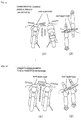
- the infrared input-output window 5 for infrared communication is provided on the side surface of the main part 1 of the device, and directed laterally relative to the advancing direction of the vehicle so that communication between vehicles may be made when they stand side by side.
- the distance between the meter sections of the vehicles may be shortened by bringing the vehicles close to each other in parallel, opposite directions as shown in FIG. 11(B) so that infrared output may be effectively utilized.
- the infrared input-output window is preferably provided on the left side of the main part 1 of the device so that the riders need not support the standing vehicles because of the side stand position as shown in FIG. 11(A) and the standing side of the rider.
- the infrared input-output windows are provided on both right and left sides, the communication may be made by letting two vehicles stand respectively on the side stands side by side as shown in FIGs. 12(A) and 12(B).
- the passing points to be remembered such as sightseeing spots and diverging roads may be recorded as memory data by longitude and latitude of a current point during driving without the rider removing a hand from the handlebar by simply pressing the memory button 7 in the handlebar switch area.
- the traveled route may be determined by displaying the stored data and referring to an atlas (carrying longitudes and latitudes), or the stored data may be downloaded to a personal computer and linked to a map software to display the traveled route.
- the place names stored in the navigation device may be used to automatically add place names to the stored longitude and latitude data of passing points.
- the clock built in the navigation device may be used to automatically add time point data to the data for the passing points so that the average vehicle speed may be calculated later.
- application of the invention is not limited to the navigation device having different functions as shown with the embodiment for motorcycles, but may also be applied to the navigation device for automobiles as a matter of course (for automobiles, the memory button may be disposed on the instrument panel near the driver seat).
- the travel device needs not necessarily be coupled with a navigation device for route guidance.
- a GPS signal can be used to determine the actual position of the vehicle.
- a place name storing means and timer are integrated in this embodiment as well as an input/output means for data exchange with an external device.
Landscapes
- Engineering & Computer Science (AREA)
- Radar, Positioning & Navigation (AREA)
- Remote Sensing (AREA)
- Physics & Mathematics (AREA)
- General Physics & Mathematics (AREA)
- Automation & Control Theory (AREA)
- Computer Networks & Wireless Communication (AREA)
- Navigation (AREA)
- Traffic Control Systems (AREA)
- Position Fixing By Use Of Radio Waves (AREA)
Applications Claiming Priority (3)
| Application Number | Priority Date | Filing Date | Title |
|---|---|---|---|
| JP18040097A JPH1114392A (ja) | 1997-06-20 | 1997-06-20 | ナビゲーション装置による走行記録方法 |
| JP180400/97 | 1997-06-20 | ||
| JP18040097 | 1997-06-20 |
Publications (2)
| Publication Number | Publication Date |
|---|---|
| EP0886124A2 true EP0886124A2 (de) | 1998-12-23 |
| EP0886124A3 EP0886124A3 (de) | 2000-05-03 |
Family
ID=16082587
Family Applications (1)
| Application Number | Title | Priority Date | Filing Date |
|---|---|---|---|
| EP98111355A Withdrawn EP0886124A3 (de) | 1997-06-20 | 1998-06-19 | Verfahren und Vorrichtung zum Speichern von Wegstreckendaten |
Country Status (2)
| Country | Link |
|---|---|
| EP (1) | EP0886124A3 (de) |
| JP (1) | JPH1114392A (de) |
Cited By (2)
| Publication number | Priority date | Publication date | Assignee | Title |
|---|---|---|---|---|
| EP1233251A3 (de) * | 2001-02-14 | 2007-11-14 | Matsushita Electric Industrial Co., Ltd. | Navigationssystem |
| CN113168738A (zh) * | 2019-03-27 | 2021-07-23 | Jvc建伍株式会社 | 记录控制装置、记录控制方法以及程序 |
Families Citing this family (1)
| Publication number | Priority date | Publication date | Assignee | Title |
|---|---|---|---|---|
| JP2003337028A (ja) * | 2002-05-20 | 2003-11-28 | Denso Corp | 二輪車及び二輪車用運転技術データ収集システム |
Family Cites Families (2)
| Publication number | Priority date | Publication date | Assignee | Title |
|---|---|---|---|---|
| US5345388A (en) * | 1991-08-06 | 1994-09-06 | Pioneer Electronic Corporation | Navigation system utilizing locus data compression |
| JP3153402B2 (ja) * | 1993-12-16 | 2001-04-09 | アルパイン株式会社 | 車載用ナビゲーション装置 |
-
1997
- 1997-06-20 JP JP18040097A patent/JPH1114392A/ja active Pending
-
1998
- 1998-06-19 EP EP98111355A patent/EP0886124A3/de not_active Withdrawn
Cited By (2)
| Publication number | Priority date | Publication date | Assignee | Title |
|---|---|---|---|---|
| EP1233251A3 (de) * | 2001-02-14 | 2007-11-14 | Matsushita Electric Industrial Co., Ltd. | Navigationssystem |
| CN113168738A (zh) * | 2019-03-27 | 2021-07-23 | Jvc建伍株式会社 | 记录控制装置、记录控制方法以及程序 |
Also Published As
| Publication number | Publication date |
|---|---|
| EP0886124A3 (de) | 2000-05-03 |
| JPH1114392A (ja) | 1999-01-22 |
Similar Documents
| Publication | Publication Date | Title |
|---|---|---|
| EP0886125A2 (de) | Fahrzeuganzeigevorrichtung | |
| US6157890A (en) | Motorcycle navigation system | |
| US6154703A (en) | Control for vehicle navigational system | |
| EP1150268B1 (de) | Verfahren und Vorrichtung zur Auswahl des Zieles bei einem Navigationssystem im Fahrzeug | |
| US6313761B1 (en) | Information receiving apparatus, positioning apparatus, navigation apparatus, information receiving method, positioning method and navigating method | |
| JPH09292262A (ja) | 周辺施設検索表示方法及び誘導経路の目的地設定方法 | |
| JP6700058B2 (ja) | 二輪車及び二輪車システム | |
| JP2000123295A (ja) | ナビゲーションセンタ装置,ナビゲーション装置,ナビゲーションシステム及び方法 | |
| JP3167619B2 (ja) | 車載用ナビゲーション装置 | |
| JP2005195536A (ja) | 自動車の運転支援システム | |
| JPH1137771A5 (de) | ||
| JP2009053231A (ja) | 道路情報作成装置、道路情報作成方法及びプログラム | |
| EP0886123A2 (de) | Navigationsvorrichtung und -verfahren | |
| JP4507333B2 (ja) | 経路探索,地図表示,ナビゲートの方法及び装置並びに自動車 | |
| JP4128444B2 (ja) | 車載ナビゲータにおける案内表示方法 | |
| EP0886124A2 (de) | Verfahren und Vorrichtung zum Speichern von Wegstreckendaten | |
| JP3940428B1 (ja) | 車両軌跡生成装置、車両軌跡生成方法、車両軌跡生成プログラムおよび車両走行支援装置 | |
| JPH1114393A (ja) | ナビゲーション装置の経由地切替方法 | |
| JP4855208B2 (ja) | 移動体情報表示装置及び移動体情報表示方法等 | |
| JP3810031B2 (ja) | 自動二輪車用ナビゲーション装置 | |
| EP1302748B1 (de) | Methode zur anzeige der benutzerführung in einem fahrzeug-navigationssystem | |
| JP3539022B2 (ja) | 車両用ナビゲーション装置 | |
| JP4145497B2 (ja) | ナビゲーション装置 | |
| JP4180471B2 (ja) | ナビゲーションシステム | |
| JP4463540B2 (ja) | 車載用ナビゲーション装置及び交通情報表示方法 |
Legal Events
| Date | Code | Title | Description |
|---|---|---|---|
| PUAI | Public reference made under article 153(3) epc to a published international application that has entered the european phase |
Free format text: ORIGINAL CODE: 0009012 |
|
| AK | Designated contracting states |
Kind code of ref document: A2 Designated state(s): DE FR GB IT |
|
| AX | Request for extension of the european patent |
Free format text: AL;LT;LV;MK;RO;SI |
|
| PUAL | Search report despatched |
Free format text: ORIGINAL CODE: 0009013 |
|
| AK | Designated contracting states |
Kind code of ref document: A3 Designated state(s): AT BE CH CY DE DK ES FI FR GB GR IE IT LI LU MC NL PT SE |
|
| AX | Request for extension of the european patent |
Free format text: AL;LT;LV;MK;RO;SI |
|
| 17P | Request for examination filed |
Effective date: 20001026 |
|
| AKX | Designation fees paid |
Free format text: DE FR GB IT |
|
| 17Q | First examination report despatched |
Effective date: 20041025 |
|
| STAA | Information on the status of an ep patent application or granted ep patent |
Free format text: STATUS: THE APPLICATION IS DEEMED TO BE WITHDRAWN |
|
| 18D | Application deemed to be withdrawn |
Effective date: 20080103 |