EP0886147A1 - Appareil pour obtenir une inductance magnétique proportionelle à un courant à l'amplacement d'un capteur de champ magnétique - Google Patents
Appareil pour obtenir une inductance magnétique proportionelle à un courant à l'amplacement d'un capteur de champ magnétique Download PDFInfo
- Publication number
- EP0886147A1 EP0886147A1 EP97112160A EP97112160A EP0886147A1 EP 0886147 A1 EP0886147 A1 EP 0886147A1 EP 97112160 A EP97112160 A EP 97112160A EP 97112160 A EP97112160 A EP 97112160A EP 0886147 A1 EP0886147 A1 EP 0886147A1
- Authority
- EP
- European Patent Office
- Prior art keywords
- web
- arrangement according
- ferromagnetic
- side surfaces
- field sensor
- Prior art date
- Legal status (The legal status is an assumption and is not a legal conclusion. Google has not performed a legal analysis and makes no representation as to the accuracy of the status listed.)
- Granted
Links
- 230000005291 magnetic effect Effects 0.000 title claims abstract description 56
- 230000006698 induction Effects 0.000 title claims description 6
- 230000005294 ferromagnetic effect Effects 0.000 claims abstract description 30
- 239000003302 ferromagnetic material Substances 0.000 claims abstract description 13
- 239000004020 conductor Substances 0.000 claims description 11
- 230000004907 flux Effects 0.000 claims description 4
- 238000000034 method Methods 0.000 claims description 2
- 238000005476 soldering Methods 0.000 claims description 2
- 238000010276 construction Methods 0.000 description 6
- 230000005611 electricity Effects 0.000 description 4
- 230000000694 effects Effects 0.000 description 2
- 239000002184 metal Substances 0.000 description 2
- TVEXGJYMHHTVKP-UHFFFAOYSA-N 6-oxabicyclo[3.2.1]oct-3-en-7-one Chemical compound C1C2C(=O)OC1C=CC2 TVEXGJYMHHTVKP-UHFFFAOYSA-N 0.000 description 1
- 239000000919 ceramic Substances 0.000 description 1
- 230000001419 dependent effect Effects 0.000 description 1
- 230000002452 interceptive effect Effects 0.000 description 1
- 238000004519 manufacturing process Methods 0.000 description 1
Images


Classifications
-
- G—PHYSICS
- G01—MEASURING; TESTING
- G01R—MEASURING ELECTRIC VARIABLES; MEASURING MAGNETIC VARIABLES
- G01R15/00—Details of measuring arrangements of the types provided for in groups G01R17/00 - G01R29/00, G01R33/00 - G01R33/26 or G01R35/00
- G01R15/14—Adaptations providing voltage or current isolation, e.g. for high-voltage or high-current networks
- G01R15/20—Adaptations providing voltage or current isolation, e.g. for high-voltage or high-current networks using galvano-magnetic devices, e.g. Hall-effect devices, i.e. measuring a magnetic field via the interaction between a current and a magnetic field, e.g. magneto resistive or Hall effect devices
- G01R15/207—Constructional details independent of the type of device used
Definitions
- the invention relates to an arrangement for achieving an electric current proportional magnetic induction at the location of a magnetic field sensor according to the generic term of claim 1.
- the arrangement is preferably in an input part of a single-phase or multi-phase electricity meter uses one or more types of energy, e.g. B. active and / or Measures reactive and / or apparent energy, possibly supplemented by determining further electrical and physical ones Parameters such as B. Power factors and / or effective values of the electrical Current and / or an electrical voltage.
- B. active and / or Measures reactive and / or apparent energy possibly supplemented by determining further electrical and physical ones Parameters such as B. Power factors and / or effective values of the electrical Current and / or an electrical voltage.
- the magnetic generated by the arrangement Induction is multiplied by a voltage in the input part of the electricity meter for the purpose Obtaining an associated electrical output, which in turn is then in the electricity meter via a Time is integrated in order to maintain the associated energy values.
- Magnetic induction can also be used in the input part of the electricity meter in order to obtain the associated one Current value.
- a measuring transducer for measuring one in a U-shape is bent electrical conductor flowing current known
- the three-legged has a ferromagnetic core, the middle leg of which has three air gaps and from electrical conductor is at least partially surrounded.
- a Magnetic field sensor e.g. B. arranged a Hall element for measuring the current or power.
- a middle leg of the core consists of two flat sheet metal strips, which together with the Magnetic field sensor are arranged in a housing made of non-ferromagnetic material. The Both outer air gaps are filled by one wall of the housing.
- a yoke and that Both outer legs of the ferromagnetic core are formed by a ring that consists of one there is an annularly bent ferromagnetic sheet.
- the ring is on its outer surface of surrounded by an approximately parallel, ring-shaped outer shield.
- the invention has for its object to an arrangement of the type mentioned realize which can be easily and cheaply manufactured and / or assembled, and one sufficiently good shielding of the magnetic field sensor against the influence of external magnetic Has interference fields.
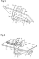
- the arrangement according to the invention for achieving a magnetic induction proportional to an electrical current i at the location of a magnetic field sensor 5 is in all variants, ie also in the first variant (see FIGS. 1 to 5), with an electrical conductor 1 and a magnetic circuit 2 Mistake.
- the electrical conductor 1 serves to conduct the electrical current i and preferably has a coil-shaped or U-shaped shape. The latter was assumed in the drawing.
- the magnetic circuit 2 made of ferromagnetic material serves to receive a magnetic flux ⁇ generated by the electrical current i. It has a ferromagnetic web 3 and an air gap 4.
- the voltage v feeds via a resistor to a feed input of the magnetic field sensor 5 assumed to be a Hall element.
- the current i also feeds a constant voltage, also not shown in the drawing the supply input of the Hall element via a resistor.
- the ferromagnetic web 3 is contained together with the magnetic field sensor 5 in a housing 6 made of non-ferromagnetic material and provided with electrical connections 6a (see FIGS.
- both ends of the ferromagnetic web 3 are connected to one another via a first means 7 made of ferromagnetic material.
- the width B of the first means 7 is greater than the greatest width b of the ferromagnetic web 3.
- the first means 7 has at least two opposing parallel partial surfaces, each of which has a side surface 7a or 7b of the first means 7.
- the two side surfaces 7a and 7b each have a free edge 8a or 8b parallel to the width b of the ferromagnetic web 3, each of which delimits a free end 9a or 9b of the relevant side surface 7a or 7b, which protrudes like a balcony.
- the ferromagnetic web 3 is arranged at a distance d from the free edges 8a and 8b of the two side surfaces 7a and 7b and approximately in the middle of the width B of the first means 7 between the parallel partial surfaces.
- the value of the distance d ie the length of the free end 9a or 9b of the side surface 7a or 7b projecting like a balcony, is preferably approximately equal to 1/3 of the total length L of the side surface 7a or 7b.
- the first means 7, perpendicular to its width B, preferably has a generally U-shaped one Cross section on.
- the two side surfaces 7a and 7b of the first means 7 are then arranged opposite each other in parallel.
- the corners of the U-shaped cross section of the By means of z. B. approximately rectangular, possibly slightly rounded.
- the second variant shown is additionally the free end 9a or 9b of the two Side surfaces 7a and 7b of the first means 7 are at least partially bent inwards.
- Outside parallel and magnetically contactless to the first means 7 is an at least approximately optional second means 10 of the same size made of ferromagnetic material, which thus, parallel to the side surfaces 7a and 7b, one of the latter belonging side surfaces 10a and 10b has (see Fig.
- the second means 10 serves as an additional magnetic shield, which protects the magnetic field sensor 5 against the influence of external magnetic interference fields.
- the Ferromagnetic material of the two means 7 and 10 is, for. B. sheet-shaped ferromagnetic Metal or ferromagnetic ceramic.
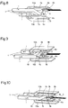
- the conductor 1 surrounds a surface of the first means 7 in all variants (see FIGS. 1 and 6 to 10) and, if present, also a surface of the second means 10 (see FIGS. 2 to 5) with at least half a turn so that the electrical current i flowing in it in the through the Web 3 and the first means 7 formed ferromagnetic magnetic circuit 2, the magnetic flux ⁇ generated.
- the conductor is U-shaped, it is either bent as it is or as it is in the Shown drawing, from a flat stamped part, in which an opening as a passage for the Areas of the two means 7 and 10 is punched. In the latter case, the opening is outward extended by a slot that separates a forward conductor 1a of conductor 1 from its return conductor 1b.
- the ferromagnetic magnetic circuit 2 is preferably on a printed circuit board 11 arranged.
- the side surfaces 7a and 7b or 10a and 10b of one or both means 7 and / or 10 are then in the first and second construction (see FIGS. 2 to 4) on a first side 11a of the Printed circuit board 11 arranged approximately perpendicular to the latter, while its free ends, 9a and 9b in the case of the first means 7, on the other, second side 11b of the printed circuit board 11 are outstandingly arranged above.
- the ferromagnetic web 3 is in this case on one of the two sides 11a and 11b of the circuit board 11 between the two side surfaces 7a and 7b of the arranged first means 7.
- the ferromagnetic web 3 with the magnetic field sensor 5 in the housing 6 provided with the electrical connections 6a is thus the latter likewise at least partially between the two side surfaces 7a and 7b of the first means 7 one of the two sides 11a or 11b of the circuit board 11 is arranged.
- the web 3 and the housing 6 z. B. on the side 11b of the circuit board 11.
- the housing 6 is arranged rotated by 90 °: in the first construction, the Longitudinal axis of the housing 6 aligned parallel to the side surfaces 7a and 7b, while in second structure is aligned perpendicular to the same. In the latter case, that crosses Housing 6 one of the side surfaces, for. B. 7a, the first means 7. In both types of construction is a part of the housing 6, which has no connections 6a, between the side surfaces 7a and 7b arranged.
- the third construction shown in FIG. 5 corresponds approximately to the first construction with the Main difference that the side surfaces 7a, 7b, 10a and 10b of the two means 7 and 10 parallel to Printed circuit board 11 are arranged.
- the two means 7 and 10 are preferably on one the two sides of the circuit board 11, e.g. B. on page 11a.
- one of the Side surfaces 10a and 10b of the second means 10 or, if this is missing, one of the Side surfaces 7a and 7b of the first means 7 (not shown in the drawing) on one of the sides 11a and 11b of the printed circuit board 11 are arranged lying on top.
- the electrical connections 6a of the housing 6 are designed in such a way that the housing 6 is either plugged normally onto the printed circuit board 11 (see FIG. 5) or by means of a so-called SMT soldering method (" S urface M ounted T echnology") on the Printed circuit board 11 can be mounted (see FIGS. 2 and 4).
- the assumption applies that the first means 7 consists of two parts 12a and 12b.
- the two parts 12a and 12b are each partially overlapping arranged one on top of the other so that non-overlapping areas of both parts 12a and 12b the height of the ferromagnetic web 3 are approximately parallel to one another.
- the two parts 12a and 12b preferably have a J-shaped or L-shaped shape perpendicular to the width B of the means 7 Cross section and are at least partially overlapping one another so that both parts 12a and 12b together have an approximately U-shaped cross section.
- the assumption applies that both parts 12a and 12b each have an L-shaped cross section with rounded Have edges.
- the ferromagnetic web 3 consists of a single web part 3a (see FIG. 8) or from two web parts 3a and 3b (see all other figures). In the former case it is Air gap 4 containing magnetic field sensor 5 between the single web part 3a and one of the two Side surfaces 7a and 7b of the first means 7 are present. In Fig. 8, the air gap 4 z. B. arranged between the single web part 3a and the side surface 7b. If the web 3 against it consists of two web parts 3a and 3b, is the air gap 4 containing the magnetic field sensor 5 preferably arranged between the two web parts 3a and 3b, the center line of one Web part 3a is preferably located in the extension of the center line of the other web part 3b.
- web part 3a or 3b is either one of one of the both side surfaces 7a and 7b of the first means 7, bent out in a balcony-like manner protruding bent part (see Fig. 9) or it is one on the inside of one of the two Side surfaces 7a and 7b of the first means 7 arranged mounting part with preferably L-shaped Cross section (see Fig. 8), with one side of the mounting part on the relevant Side surface 7a or 7b is mounted lying on, while the other side of the mounting part protrudes toward the inside like a balcony.
- the top view of the web part 3a or 3b (see FIGS. 1 to 7) or one end of the web part 3a or 3b (see FIGS. 8 and 9) is, for. B to realize the narrowing trapezoidal, the parallel side of the trapezoid in each case run parallel to the side surfaces 7a and 7b.
- the web part 3a or 3b is in each case tablet-shaped and one of the inside both side surfaces 7a and 7b of the first means 7 with its axis of rotation perpendicular to the same arranged.
Landscapes
- Physics & Mathematics (AREA)
- General Physics & Mathematics (AREA)
- Measuring Magnetic Variables (AREA)
- Shielding Devices Or Components To Electric Or Magnetic Fields (AREA)
Priority Applications (1)
| Application Number | Priority Date | Filing Date | Title |
|---|---|---|---|
| SI9730782T SI0886147T1 (sl) | 1997-05-21 | 1997-07-16 | Razmestitev za dosego električnemu toku sorazmerne gostote magnetnega polja na mestu senzorja magnetnega polja |
Applications Claiming Priority (2)
| Application Number | Priority Date | Filing Date | Title |
|---|---|---|---|
| CH118297 | 1997-05-21 | ||
| CH1182/97 | 1997-05-21 |
Publications (2)
| Publication Number | Publication Date |
|---|---|
| EP0886147A1 true EP0886147A1 (fr) | 1998-12-23 |
| EP0886147B1 EP0886147B1 (fr) | 2008-09-17 |
Family
ID=4204424
Family Applications (1)
| Application Number | Title | Priority Date | Filing Date |
|---|---|---|---|
| EP19970112160 Expired - Lifetime EP0886147B1 (fr) | 1997-05-21 | 1997-07-16 | Appareil pour obtenir une inductance magnétique proportionelle à un courant à l'emplacement d'un capteur de champ magnétique |
Country Status (3)
| Country | Link |
|---|---|
| EP (1) | EP0886147B1 (fr) |
| DE (1) | DE59712967D1 (fr) |
| SI (1) | SI0886147T1 (fr) |
Cited By (11)
| Publication number | Priority date | Publication date | Assignee | Title |
|---|---|---|---|---|
| WO2001086309A1 (fr) * | 2000-05-09 | 2001-11-15 | Siemens Metering Ag | Ensemble circuit magnetique pour determiner un courant electrique |
| DE10032826A1 (de) * | 2000-07-06 | 2002-01-31 | Infineon Technologies Ag | Stromsensor und dessen Verwendung |
| DE102006032763A1 (de) * | 2006-07-14 | 2008-01-17 | Lisa Dräxlmaier GmbH | Vorrichtung und Verfahren zur Messung eines in einem elektrischen Leiter fließenden Stromes |
| US7545136B2 (en) | 2006-01-19 | 2009-06-09 | Melexis Technologies Sa | Device for measuring current |
| US7579825B2 (en) | 2006-07-14 | 2009-08-25 | Lisa Dräxlmaier GmbH | Device and method for measuring a current flowing in an electrical conductor |
| FR3030762A1 (fr) * | 2014-12-18 | 2016-06-24 | Renault Sa | Capteur de courant pour la mesure d'un courant electrique |
| EP3211436A1 (fr) * | 2016-02-29 | 2017-08-30 | Wöhner GmbH & Co. KG Elektrotechnische Systeme | Dispositif de mesure de courant sans contact |
| WO2017148823A1 (fr) * | 2016-02-29 | 2017-09-08 | Wöhner GmbH & Co. KG Elektrotechnische Systeme | Dispositif de mesure de courant sans contact |
| US9859831B2 (en) | 2014-12-18 | 2018-01-02 | Caterpillar Inc. | Control system using flux feedback |
| EP3309559A1 (fr) * | 2016-10-11 | 2018-04-18 | LEM Intellectual Property SA | Transducteur de courant électrique |
| EP3817214A4 (fr) * | 2018-06-26 | 2021-08-25 | Mitsubishi Electric Corporation | Dispositif de conversion d'énergie |
Citations (5)
| Publication number | Priority date | Publication date | Assignee | Title |
|---|---|---|---|---|
| CH659138A5 (en) * | 1982-10-27 | 1986-12-31 | Landis & Gyr Ag | Arrangement for measuring the current flowing in an electrical conductor via the magnetic field generated by it |
| US4742296A (en) * | 1986-02-10 | 1988-05-03 | Lgz Landis & Gyr Zug Ag | Arrangement for measuring electrical power |
| EP0618451A1 (fr) * | 1993-03-05 | 1994-10-05 | Deutsche Zaehler-Gesellschaft | Capteur de courant en particulier pour un compteur d'énergie électrique |
| JPH0815330A (ja) * | 1994-06-28 | 1996-01-19 | Tokin Corp | 電流検出器 |
| JPH08241821A (ja) * | 1995-03-02 | 1996-09-17 | Osaki Electric Co Ltd | 電流変成器 |
-
1997
- 1997-07-16 EP EP19970112160 patent/EP0886147B1/fr not_active Expired - Lifetime
- 1997-07-16 DE DE59712967T patent/DE59712967D1/de not_active Expired - Lifetime
- 1997-07-16 SI SI9730782T patent/SI0886147T1/sl unknown
Patent Citations (5)
| Publication number | Priority date | Publication date | Assignee | Title |
|---|---|---|---|---|
| CH659138A5 (en) * | 1982-10-27 | 1986-12-31 | Landis & Gyr Ag | Arrangement for measuring the current flowing in an electrical conductor via the magnetic field generated by it |
| US4742296A (en) * | 1986-02-10 | 1988-05-03 | Lgz Landis & Gyr Zug Ag | Arrangement for measuring electrical power |
| EP0618451A1 (fr) * | 1993-03-05 | 1994-10-05 | Deutsche Zaehler-Gesellschaft | Capteur de courant en particulier pour un compteur d'énergie électrique |
| JPH0815330A (ja) * | 1994-06-28 | 1996-01-19 | Tokin Corp | 電流検出器 |
| JPH08241821A (ja) * | 1995-03-02 | 1996-09-17 | Osaki Electric Co Ltd | 電流変成器 |
Non-Patent Citations (2)
| Title |
|---|
| PATENT ABSTRACTS OF JAPAN vol. 096, no. 005 31 May 1996 (1996-05-31) * |
| PATENT ABSTRACTS OF JAPAN vol. 097, no. 001 31 January 1997 (1997-01-31) * |
Cited By (19)
| Publication number | Priority date | Publication date | Assignee | Title |
|---|---|---|---|---|
| DE10022316A1 (de) * | 2000-05-09 | 2001-11-22 | Siemens Metering Ag Zug | Magnetkreisanordnung zur Bestimmung eines elektrischen Stroms |
| WO2001086309A1 (fr) * | 2000-05-09 | 2001-11-15 | Siemens Metering Ag | Ensemble circuit magnetique pour determiner un courant electrique |
| DE10032826A1 (de) * | 2000-07-06 | 2002-01-31 | Infineon Technologies Ag | Stromsensor und dessen Verwendung |
| EP1811311B1 (fr) * | 2006-01-19 | 2016-08-31 | Melexis Technologies NV | Dispositif pour mesurer le courant |
| US7545136B2 (en) | 2006-01-19 | 2009-06-09 | Melexis Technologies Sa | Device for measuring current |
| DE102006032763A1 (de) * | 2006-07-14 | 2008-01-17 | Lisa Dräxlmaier GmbH | Vorrichtung und Verfahren zur Messung eines in einem elektrischen Leiter fließenden Stromes |
| DE102006032763B4 (de) * | 2006-07-14 | 2009-05-07 | Lisa Dräxlmaier GmbH | Vorrichtung und Verfahren zur Messung eines in einem elektrischen Leiter fließenden Stromes |
| US7579825B2 (en) | 2006-07-14 | 2009-08-25 | Lisa Dräxlmaier GmbH | Device and method for measuring a current flowing in an electrical conductor |
| US7923986B2 (en) | 2006-07-14 | 2011-04-12 | Lisa Draexlmaier Gmbh | Device and method for measuring a current flowing in an electrical conductor |
| FR3030762A1 (fr) * | 2014-12-18 | 2016-06-24 | Renault Sa | Capteur de courant pour la mesure d'un courant electrique |
| US9859831B2 (en) | 2014-12-18 | 2018-01-02 | Caterpillar Inc. | Control system using flux feedback |
| EP3211436A1 (fr) * | 2016-02-29 | 2017-08-30 | Wöhner GmbH & Co. KG Elektrotechnische Systeme | Dispositif de mesure de courant sans contact |
| WO2017148823A1 (fr) * | 2016-02-29 | 2017-09-08 | Wöhner GmbH & Co. KG Elektrotechnische Systeme | Dispositif de mesure de courant sans contact |
| EP3309559A1 (fr) * | 2016-10-11 | 2018-04-18 | LEM Intellectual Property SA | Transducteur de courant électrique |
| WO2018069166A1 (fr) * | 2016-10-11 | 2018-04-19 | Lem Intellectual Property Sa | Transducteur de courant électrique |
| CN109804255A (zh) * | 2016-10-11 | 2019-05-24 | 莱姆知识产权股份有限公司 | 电流换能器 |
| US10989740B2 (en) | 2016-10-11 | 2021-04-27 | Lem International Sa | Closed-loop current transducer |
| CN109804255B (zh) * | 2016-10-11 | 2021-05-11 | 莱姆电子(中国)有限公司 | 电流换能器 |
| EP3817214A4 (fr) * | 2018-06-26 | 2021-08-25 | Mitsubishi Electric Corporation | Dispositif de conversion d'énergie |
Also Published As
| Publication number | Publication date |
|---|---|
| EP0886147B1 (fr) | 2008-09-17 |
| SI0886147T1 (sl) | 2008-12-31 |
| DE59712967D1 (de) | 2008-10-30 |
Similar Documents
| Publication | Publication Date | Title |
|---|---|---|
| DE69604280T2 (de) | Elektrischer stromsensor | |
| EP0061520B2 (fr) | Transducteur de mesure sans noyau magnétique pour la mesure d'un courant sans contact direct | |
| EP0233988B1 (fr) | Convertisseur de courant pour mesurer un courant passant dans un conducteur électrique | |
| DE102015009603B4 (de) | Vorrichtung zum messen eines elektrischen stromes durch eine stromschiene | |
| EP0262293B1 (fr) | Transformateur pour la mesure d'un courant qui circule dans un conducteur électrique | |
| DE112009000933T5 (de) | Induktiver Linear-Stellungssensor | |
| DE2433645C3 (de) | Magnetoresistives Bauelement | |
| DE19606445A1 (de) | Induktive Messvorrichtung zur Messung von einem hohen Gleichstrom überlagerten Wechelstromkomponenten | |
| DE3741028A1 (de) | Stromwandlervorrichtung zum messen eines elektrischen stromes | |
| DE3130277A1 (de) | Magnetkern aus weichmagnetischem material fuer einen stromsensor mit einem magnetfeldabhaengigen halbleiterelement zur erfassung von gleich- und wechselstroemen | |
| EP0886147B1 (fr) | Appareil pour obtenir une inductance magnétique proportionelle à un courant à l'emplacement d'un capteur de champ magnétique | |
| CH661142A5 (de) | Aktiver stromsensor. | |
| EP0292636A1 (fr) | Convertisseur de courant pour mesurer un courant passant dans un conducteur électrique | |
| DE19542899B4 (de) | Wechselstromsensor auf der Basis einer Parallelplattengeometrie und mit einem Shunt zur Selbstspeisung | |
| WO2009019200A1 (fr) | Dispositif de mesure d'un courant circulant dans un conducteur électrique | |
| DE102005028572B4 (de) | Stromsensoranordung mit einem Magnetkern | |
| EP1059506A2 (fr) | Aimant pour palpeur de position | |
| DE10011047B4 (de) | Direktabbildender Stromsensor | |
| DE2539877C3 (de) | Elektrischer Impulserzeuger | |
| DE19535551C2 (de) | Stromwandleranordnung mit einem Shunt | |
| DE29818370U1 (de) | Einrichtung zur Messung des in einem Leiter, insbesondere einem Streifenleiter fließenden Stroms, sowie Streifenleiter hierfür | |
| DE2122420A1 (de) | Magnetometer | |
| DE10022316A1 (de) | Magnetkreisanordnung zur Bestimmung eines elektrischen Stroms | |
| DE3742936A1 (de) | Anordnung zur messung von ferromagnetischen verschlussteilen in der fluessigkeit eines maschinen-kreislaufsystems | |
| DE102024105563A1 (de) | Vorrichtung zur Messung eines Differenzstroms |
Legal Events
| Date | Code | Title | Description |
|---|---|---|---|
| PUAI | Public reference made under article 153(3) epc to a published international application that has entered the european phase |
Free format text: ORIGINAL CODE: 0009012 |
|
| AK | Designated contracting states |
Kind code of ref document: A1 Designated state(s): CH DE LI SE |
|
| AX | Request for extension of the european patent |
Free format text: AL;LT;LV;RO;SI |
|
| 17P | Request for examination filed |
Effective date: 19990623 |
|
| AKX | Designation fees paid |
Free format text: CH DE LI SE |
|
| AXX | Extension fees paid |
Free format text: SI PAYMENT 19990623 |
|
| RAP1 | Party data changed (applicant data changed or rights of an application transferred) |
Owner name: SIEMENS METERING AG |
|
| RAP1 | Party data changed (applicant data changed or rights of an application transferred) |
Owner name: LANDIS + GYR AG |
|
| RAP1 | Party data changed (applicant data changed or rights of an application transferred) |
Owner name: LANDIS+GYR AG |
|
| RIC1 | Information provided on ipc code assigned before grant |
Ipc: 7G 01R 33/02 B Ipc: 7G 01R 15/20 A |
|
| 17Q | First examination report despatched |
Effective date: 20050309 |
|
| RIN1 | Information on inventor provided before grant (corrected) |
Inventor name: JANSSEN, PETER Inventor name: PETR, JAN |
|
| GRAP | Despatch of communication of intention to grant a patent |
Free format text: ORIGINAL CODE: EPIDOSNIGR1 |
|
| GRAS | Grant fee paid |
Free format text: ORIGINAL CODE: EPIDOSNIGR3 |
|
| GRAA | (expected) grant |
Free format text: ORIGINAL CODE: 0009210 |
|
| AK | Designated contracting states |
Kind code of ref document: B1 Designated state(s): CH DE LI SE |
|
| AX | Request for extension of the european patent |
Extension state: SI |
|
| REG | Reference to a national code |
Ref country code: CH Ref legal event code: EP |
|
| REF | Corresponds to: |
Ref document number: 59712967 Country of ref document: DE Date of ref document: 20081030 Kind code of ref document: P |
|
| REG | Reference to a national code |
Ref country code: CH Ref legal event code: NV Representative=s name: RENTSCH & PARTNER |
|
| PLBE | No opposition filed within time limit |
Free format text: ORIGINAL CODE: 0009261 |
|
| STAA | Information on the status of an ep patent application or granted ep patent |
Free format text: STATUS: NO OPPOSITION FILED WITHIN TIME LIMIT |
|
| 26N | No opposition filed |
Effective date: 20090618 |
|
| PG25 | Lapsed in a contracting state [announced via postgrant information from national office to epo] |
Ref country code: SE Free format text: LAPSE BECAUSE OF FAILURE TO SUBMIT A TRANSLATION OF THE DESCRIPTION OR TO PAY THE FEE WITHIN THE PRESCRIBED TIME-LIMIT Effective date: 20081217 |
|
| REG | Reference to a national code |
Ref country code: CH Ref legal event code: PFA Owner name: LANDIS+GYR AG Free format text: LANDIS+GYR AG#FELDSTRASSE 1#6301 ZUG (CH) -TRANSFER TO- LANDIS+GYR AG#FELDSTRASSE 1#6301 ZUG (CH) |
|
| REG | Reference to a national code |
Ref country code: CH Ref legal event code: NV Representative=s name: WEINMANN ZIMMERLI, CH |
|
| REG | Reference to a national code |
Ref country code: CH Ref legal event code: PCOW Free format text: NEW ADDRESS: THEILERSTRASSE 1, 6301 ZUG (CH) |
|
| REG | Reference to a national code |
Ref country code: CH Ref legal event code: NV Representative=s name: RENTSCH PARTNER AG, CH |
|
| PGFP | Annual fee paid to national office [announced via postgrant information from national office to epo] |
Ref country code: CH Payment date: 20160721 Year of fee payment: 20 Ref country code: DE Payment date: 20160722 Year of fee payment: 20 |
|
| REG | Reference to a national code |
Ref country code: CH Ref legal event code: NV Representative=s name: CMSRK RENTSCH KAELIN AG, CH |
|
| REG | Reference to a national code |
Ref country code: CH Ref legal event code: PFA Owner name: LANDIS+GYR AG, CH Free format text: FORMER OWNER: LANDIS+GYR AG, CH |
|
| REG | Reference to a national code |
Ref country code: DE Ref legal event code: R071 Ref document number: 59712967 Country of ref document: DE |
|
| REG | Reference to a national code |
Ref country code: CH Ref legal event code: PL |