EP0886157B1 - Câble optique et câble optique en nappe - Google Patents
Câble optique et câble optique en nappe Download PDFInfo
- Publication number
- EP0886157B1 EP0886157B1 EP19980111067 EP98111067A EP0886157B1 EP 0886157 B1 EP0886157 B1 EP 0886157B1 EP 19980111067 EP19980111067 EP 19980111067 EP 98111067 A EP98111067 A EP 98111067A EP 0886157 B1 EP0886157 B1 EP 0886157B1
- Authority
- EP
- European Patent Office
- Prior art keywords
- optical fiber
- cord
- fiber
- coat
- mono
- Prior art date
- Legal status (The legal status is an assumption and is not a legal conclusion. Google has not performed a legal analysis and makes no representation as to the accuracy of the status listed.)
- Expired - Lifetime
Links
Images





Classifications
-
- G—PHYSICS
- G02—OPTICS
- G02B—OPTICAL ELEMENTS, SYSTEMS OR APPARATUS
- G02B6/00—Light guides; Structural details of arrangements comprising light guides and other optical elements, e.g. couplings
- G02B6/44—Mechanical structures for providing tensile strength and external protection for fibres, e.g. optical transmission cables
- G02B6/4401—Optical cables
- G02B6/4403—Optical cables with ribbon structure
- G02B6/4404—Multi-podded
-
- G—PHYSICS
- G02—OPTICS
- G02B—OPTICAL ELEMENTS, SYSTEMS OR APPARATUS
- G02B6/00—Light guides; Structural details of arrangements comprising light guides and other optical elements, e.g. couplings
- G02B6/44—Mechanical structures for providing tensile strength and external protection for fibres, e.g. optical transmission cables
- G02B6/4401—Optical cables
- G02B6/4403—Optical cables with ribbon structure
-
- G—PHYSICS
- G02—OPTICS
- G02B—OPTICAL ELEMENTS, SYSTEMS OR APPARATUS
- G02B6/00—Light guides; Structural details of arrangements comprising light guides and other optical elements, e.g. couplings
- G02B6/44—Mechanical structures for providing tensile strength and external protection for fibres, e.g. optical transmission cables
- G02B6/4401—Optical cables
- G02B6/4429—Means specially adapted for strengthening or protecting the cables
- G02B6/4434—Central member to take up tensile loads
Definitions
- the present invention relates to an optical fiber cord and an optical cord ribbon.
- an optical fiber cord of a specific structure such as the one being formed by applying reinforcing members of high-resiliency along the longitudinal direction of a coated fiber, and by coating synthetic resin therearound, is needed.
- FIG. 20 shows an explanatory view showing a sectional surface of a conventional mono-fiber type optical fiber cord.
- FIG. 21 shows a multi-fiber type optical fiber cord.
- the mono-fiber type optical fiber cord 3 in FIG. 20 (hereinafter referred to simply as “mono-fiber cord”) shows a structure that an optical fiber 11 and a coat 32 applied thereto (hereinafter referred to as an "optical-fiber coat” or just “fiber coat”) configures a coated optical fiber 33, and a reinforcing member 34 and an outer sheath 35 are applied to the outermost side thereof.
- the outside diameter of a standard coated fiber is normally 0.25 to 0.9 mm, and that of the optical fiber cord 3 containing the coated fiber is at least 1.7 mm or so.
- the reinforcing member 34 (hereinafter may be referred to just as “strength member”) is, in most occasions, made of aramid yarn. In this way, the optical fiber cord 3 is made much larger in size than the coated optical fiber 33 itself. Accordingly, since cables formed by assembling a plurality of mono-fiber cords are conventionally used for an office-site cable distribution, there has been a problem that if the number of cords to be assembled is increased, the total size thereof is made extremely large, and thus a lot of space for cable distribution is needed.
- the multi-fiber type optical fiber cord 4 (hereinafter referred to simply as a "multi-fiber cord") shown in FIG. 21 is constructed such that four coated optical fibers 33 each formed by an optical fiber 11 and an optical fiber coat 32 are laterally aligned (in the case of the figure), a bundling coat 41 is applied integrally to the thus aligned coated fibers 33 to form an optical fiber ribbon, the external face of the thus formed fiber ribbon is supported by aramid yarn in the longitudinal direction thereof as a strength member 42, and further an outer sheath 43 made of synthetic resin is applied therearound.
- the multi-fiber cord 4 formed in the above manner normally adopts four-fiber or eight-fiber optical fiber ribbon therein.
- connection or "connecting” includes the meaning of "splice” or “splicing” throughout the present specification.
- a mono-multi or multi-mono cord conversion two methods have been adopted to perform a mono-cord to multiple-cord conversion or the other way round (hereinafter referred to just as a mono-multi or multi-mono cord conversion).
- One of the methods is to form a connection point, which, though, will raise a total cost as it requires for connecting operations and connecting members.
- the other method is to open up the leading end of the multi-fiber cord to divide it to a plurality of individual coated fibers, and thereafter cover each of the coated fibers by tubes to form a plurality of optical fiber cords.
- FIG. 22 One of the structures disclosed in the paper is shown in FIG. 22 , which has an outside diameter of 0.25mm, and the diameter of the coated optical fiber itself is 0.15 mm.
- this fiber cord has completed the purpose of minimizing the diameter thereof, as a plurality of steel wires (12 wires in the figure) each having a diameter of 0.045 mm are provided around the coated optical fiber, the removing operation of the coat for the optical fiber is made more difficult. Further, as the outside diameter of the coated fiber is made smaller than 0.25 mm, the fiber coat is also made thin and thus it gets readily damaged.
- the present invention has been achieved to solve the above-described problem and an object of the present invention is to provide an optical fiber cord and an optical cord ribbon capable of minimizing the outside diameter thereof, providing an easy mono-multi or multi-mono cord conversion, and also suitable for mutual multi-fiber connection of the fiber cord ribbons.
- a mono-fiber type optical fiber cord is constructed such that it comprises: a coated optical fiber composed of an optical fiber and a fiber coat for covering the optical fiber; a coat for coated optical fiber that covers the coated fiber, and having a substantially rectangular sectional surface; and a reinforcing member within the coat for coated optical fiber, wherein the reinforcing member is located along one of the shorter sides of the coat in the substantially parallel direction therewith in such a manner as to be embedded along the longitudinally extending direction of the coated optical fiber.
- the mono-fiber type optical fiber cord according to the present invention may also be constructed in such a manner as to be provided with a protection jacket that coats the mono-fiber cord.
- the optical cord ribbon according to the present invention is constructed such that it comprises: a plurality of mono-fiber type optical fiber cords, and a bundling coat for integrally coating the plurality of mono-fiber type optical fiber cords: each of which plurality of mono-fiber type optical fiber cords having; a coated optical fiber composed of an optical fiber and a fiber coat for covering the optical fiber; a coat for coated optical fiber for covering the coated fiber, and having a substantially rectangular sectional surface; and a reinforcing member within the coat for coated optical fiber, wherein the reinforcing member is located along one of the shorter sides of the coat in the substantially parallel direction with the shorter sides in such a manner as to be embedded along the longitudinally extending direction of said coated optical fiber, while the bundling coat is integrally coated on the plurality of mono-fiber type optical fiber cords, the longer sides of adjacent mono-fiber type fiber cords being abutted to each other, and each of the reinforcing members are aligned in a side-by-side manner altogether.
- the coat for protecting the optical fiber cord and the optical cord ribbon according to the present invention are both made of an ultraviolet curing resin, wherein the latter coat can be destructed more easily than the former coat.
- the mono-fiber type optical fiber cord can be made thinner and lighter, yet a destruction due to the bending force can be prevented.
- the locations of the strength members are eccentrically biased towards one side of the coated fiber, so that an optical cord ribbon can be constructed by combining a plurality of the mono-fiber type optical fiber cords.
- the optical cord ribbon of the present invention as the strength members are eccentrically biased towards one side of the coated fibers, these strength members can be readily removed in case for connection of the optical fibers.
- FIG. 1 is a sectional view showing an embodiment of a mono-fiber cord 1 according to the present invention.
- the optical fiber 11 and a fiber coat 12 applied to the optical fiber 11 configure a coated optical fiber 13.
- the coated optical fiber 13 and two reinforcing rods 14 (hereinafter referred to just as “strength rods") configuring the strength member are coated by a coat for mono-fiber cord 15 having a substantially square sectional surface, configuring an optical fiber cord 1.
- the strength rods 14 are put in a side-by-side manner along and in parallel with one of the shorter sides of the coat for mono-fiber cord 15, in an embedded form along the longitudinal direction of the coated optical fiber 13.
- the construction of the strength rods includes a case in which a plurality of strength rods are applied in a side-by-side manner to configure a flat member as a whole as shown in FIG. 1 and FIGs. 3 to 7 .
- a and B denote a longer side and a shorter side of the sectional surface of the optical fiber cord 1, respectively. It is preferable if the two strength rods 14 are in contact with the coated optical fiber 13, and located in the symmetrical manner with respect to the center axis line C of the sectional surface of the cord, which is in parallel with the longer sides of the optical fiber cord 1.
- the fiber coat 12 and the coat for mono- fiber cord 15 As a material for the fiber coat 12 and the coat for mono- fiber cord 15, the most popular one to be adopted is an ultraviolet-curing acrylic resin.
- the elastic modulus of the acrylic resin can be easily adjusted in a wide range. Because the fiber coat 12 functions as a cushion layer, a micro-bend of the optical fiber caused by the thermal shrinking of the outer sheath can be effectively prevented, so that an optical loss can be minimized.
- the strength rod 14 steel, simple glass fiber or fiber -reinforced plastics (hereinafter referred to just as "FRP") can be adopted.
- FRP fiber -reinforced plastics
- Steel is effective for acquiring large strength and flexural rigidity, due to the fact that its elastic coefficient is higher than that of other materials.
- the steel rod can be made in a simple mono-filament structure or in a strand by stranding a plurality of very thin wires, but the mono-filament structure is more suitable for the strength rod 14 of the present invention, as it can give larger flexural rigidity and higher compression durability to the optical cord.
- an anti-rust process such as enamel coating or plating thereto.
- a stainless steel is adopted for the strength rod 14, such a process is not necessary.
- a pure-silica glass which is produced by the same process as that for producing the optical fiber 11 is most suitable. Since the pure-silica glass is chemically synthesized, contaminations and defects are very rare, and thus the strength thereof is quite high.
- the coating process for protecting the surface of the pure-silica glass is essential. It suffices that the coating applied thereto is of several- micron thick, so that such a material as epoxy whose elastic modulus is quite high may be employed. If a material that can improve the bondage with the coat for mono-fiber cord 15 is selected as a coating material, the characteristic for reinforcing the glass rod can be raised.
- the coating for the glass fiber as the strength rod 14 can be the same material as that of the optical fiber coat 12, and in this case, it can be readily manufactured. Since this simple glass fiber is used only as the strength rod 14, no core structure for leading lights therein is necessary, so that the dimension thereof can be made much more roughly than when it is used as an optical fiber, enabling thus its manufacturing at quite a low cost.
- an FRP can be used, which is produced by hardening, for example, aramid yarn, PBO (polyparaphenylenebenzobisoxazole) yarn, glass fiber yarn, or carbon fiber yarn, with epoxy resin.
- coating for the strength rod 14 itself is not shown, and this is because there is a case in which, as mentioned hereinabove, it is essential to have a coating layer just like the case of the glass fiber, and also a case in which it is not necessary just like the case of the steel wire. There is also a case in which although a coating layer is not necessary for maintaining the durability of the material, a colored coat may be applied to the strength member just for identifying the optical fiber cords.
- the optical fiber cord is constructed such that a plurality of reinforcing members are applied around the coated optical fiber, and PVC (polyvinyl chloride) jacket is further applied thereto.
- PVC polyvinyl chloride
- an optical fiber cord of the present invention is constructed such that it is not provided with a plurality of reinforcing members surrounding the entire external surface of the coated fiber, and that it can be changed into a suitable structure for constructing an optical cord ribbon by combining a plurality of mono-fiber cord units, and also since it is structured in such a manner as to enable to greatly minimize the sectional area of each mono-fiber cord unit, the optical cord ribbon as a whole can be made extremely light and small in size.
- the optical fiber cord of the present invention features that the coat is readily removed, the construction thereof is simple, and it can use the standard coated optical fibers of 0.25 mm-diameter, so that it is suitable for economizing the whole construction.
- FIG. 2 is a sectional view showing an example of the optical cord ribbon of the present invention.
- the mono-fiber cord shown in FIG. 1 is considered to be one unit, and a plurality of these units are used therein.
- one of the longer sides B of one unit optical fiber cord 1 and that of the other unit optical fiber cord 1 are mutually bonded and made integral, and a bundling coat 21 is applied to the thus integrated structure so as to form a ribbon.
- a plurality of mono-fiber cords must be arranged such that the mutually facing longer sides B of the adjacent sectional surfaces thereof are brought into contact, and that the strength rods 14 of the respective fiber cord units are aligned in a side-by-side manner.
- the bundling coat 21 instead of applying the bundling coat 21, it will be sufficient if only the mutually contacting surfaces of the mono-fiber cord units are bonded. Further, it can be even arranged in such a manner as to bond the mutual contacting surfaces first, and thereafter to apply the bundling coat.
- the shorter side A of the mono-fiber cord 1 is arranged in such a manner that the interval between two adjacent mono-fiber cord units when they are aligned with their longer sides B mutually contacted is equal to the interval P ( FIG. 21 ) between the two adjacent coated fibers in a conventionally used optical fiber ribbon.
- this interval P in the conventional optical fiber ribbon is set to 0.25 mm
- the sectional area of the mono-fiber cord 1 will be: longer side x shorter side, or 0.25 mm x 0.4 mm, approximately.
- the sectional area of the optical fiber cord 1 of the present invention is 1/30 of the case of a commercially available optical fiber cord having an outside diameter of 2 mm as shown in FIG. 20 .
- the optical fiber 11 In the structure of the mono-fiber cord 1 of the present invention, it is preferable to locate the optical fiber 11 in the center of the width (shown by an arrow A) of sectional surface of the fiber cord, or the center axis C thereof. By this arrangement of symmetrical arrangement of the optical fiber within a unit, the alignment for making a ribbon together with other optical fiber cords will be facilitated.
- the optical fiber ribbons currently used in Japan include 4 or 8 fibers, and the optical fiber ribbons of 16 fibers are now being developed. Further, the optical fiber ribbons of 12 fibers are used in other countries. It is preferable to adjust the number of mono-fiber cords to be accommodated within an optical cord ribbon of the present invention to that of the number of the fibers in an optical fiber ribbon to be connected.
- the interval between the adjacent coated fibers accommodated within the optical cord ribbon of the present invention is deflected from 0.25 mm to 0.27 mm, it will not become an impediment for its connection to a conventional optical fiber ribbon, so that it is possible to construct an optical fiber cord of the present invention having an outside diameter of 0.27 mm including a coat for mono-fiber cord 15, by use of a coated fiber having a standard outside diameter of 0.25 mm.
- the coated fibers of the present invention can be commonly used with a conventional optical fiber ribbon to enable a mass-production thereof, and thus they can be produced at a substantially low cost compared with the case in which the specific dimension is required.
- the interval between two adjacent optical fibers can be made less than 0.25 mm by using optical fibers without the outer layers. For example, if the interval is approximately 0.23 mm, it can be connected with an optical fiber ribbon having an interval of 0.25 mm between two adjacent optical fibers therein without any serious problem.
- FIGs. 3 to 7 five further different embodiments of the strength member of the present invention are shown, in each of which the construction as a whole is same as that of FIG. 1 except that the respective shapes of the strength rods as the strength member are different from one another.
- a pair of strength rods 16 are used, the sectional surface of each being a rectangular, or substantially rectangular formed by making the respective four corners thereof rounded.
- a pair of strength rods 17 are used, the sectional surface of each being oval, or elongated circle.
- a pair of strength rods 18 are used, the sectional surface of each being a right-angled triangle, or a substantially right-angled triangle formed by making the respective three corners thereof rounded, wherein each of the oblique sides is close to the coated optical fiber.
- a pair of strength rods 19 are used, the sectional surface of each being substantially pentagon, which is formed by removing the corner at the close proximity of the coated optical fiber from the rectangular of the embodiment of FIG. 3 .
- three circular strength rods 20, 20, and 22 are used. In this case, it is preferable to form the rod 22 sandwiched between the other two rods 20 smaller in diameter than that of the rod 20, so as to make the outer side surfaces of these three rods aligned to one level.
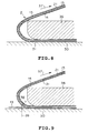
- the coated optical fiber 13 makes a flaw on the coated optical fiber 13 by pushing a blade against or scratching with it the surface where the optical fiber 11 resides, at a position relevant length away from the far end of the optical cord ribbon 2, and bend the cord ribbon 2 in the direction in which the thus made flaw faces outside.
- the coated optical fiber 13 is broken at the position 31 in FIG. 8 , while the strength rods 14 are not broken.
- the connecting method after the removal of the strength rods and the coat is same as the conventional method for mutually connecting optical fiber ribbons.
- the connection between the optical cord ribbon and mono-fiber cords can be performed by the same procedure after dividing the optical cord ribbon into individual mono-fiber cord units.
- the optical fiber cords of the present invention can be divided into individual units, and thus there is no need for providing a connecting portion when converting into the mono-fiber cords, which is a great advantage. If an optical connector is individually provided to the end portion of the thus converted mono-fiber cord, the number of fiber connecting points in the middle of the distribution can be greatly reduced.
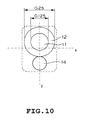
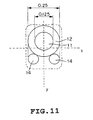
- FIGs. 10 and 11 are illustrations respectively showing an analytical model for this structure, wherein FIG. 10 explains the case in which only one strength rod is used, and FIG. 11 explains the case in which two strength rods are used.
- This analysis is based on the assumption that a standard coated optical fiber (the outside diameter of the optical fiber 0.125 mm, and that of the fiber coat is 0.25 mm) is used, and the strength rods 14 are in contact with the coated optical fiber as shown in FIGs. 10 and 11 .
- the elastic modulus (Young's modulus) for the optical fiber is 7200 kgf/mm 2
- that for the mono-filament steel wire is 21000 kgf/mm 2 .
- the lines indicated by x and y are neutral surfaces of applied bending force respectively.
- y is the neutral surface
- x is the neutral surface.
- FIGs. 10 and 11 the result of the calculation about the relation between the diameter of the strength rod (steel wire) and the flexural rigidity of the optical fiber cord are shown, respectively in FIG. 12 and FIG. 13 .
- H1x and H1y indicate flexural rigidity of the respective neutral surfaces x and y in a case in which only one steel wire is provided
- H2x and H2y indicate flexural rigidity of the respective neutral surfaces x and y in a case in which two steel wires are provided.
- the upper limit of the diameter of the steel wire is 0.25 mm when there is only one steel wire, and 0.125 mm when there are two.
- the flexural rigidity of the mono-fiber cord it is preferable to make the flexural rigidity large.
- H1y and H1x are quite different from each other, so that when the diameter of the steel wire is made large, even though the value of H1y is not so increased, that of H1x is largely increased.
- the diameter of the steel wire should be 0.17 mm in consideration for the value of H1y.
- the flexural rigidity of the case of 8-fiber optical cord ribbon becomes 35kgf.mm 2 , which is too large for practical handling because of the lack of flexibility.
- the value of H2x and that of H2y are relatively close to each other.
- the diameter of the steel wire will be approximately 0.085 mm from the curve line of H2y, and the value of H2x thus becomes approximately 1.55 kgf.mm 2 , whereby when it is made to be 8-fiber optical cord ribbon, the flexural rigidity becomes approximately 12.4 kgf.mm 2 .
- the flexural rigidity of a conventional mono-fiber cord with an outside diameter of 1.7 mm or 2.0 mm will be approximately 3 to 5 kgf.mm 2 .
- the flexural rigidity of the above mono-fiber cord is 1 kgf.mm 2 which is smaller than this 3 to 5 kgf.mm 2 , it is more or less the same as that of the conventional nylon coated optical fiber with an outside diameter of 0.9 mm, and thus it is satisfactory.
- the optical fiber ribbon is often distributed with a nylon protective tube covering therearound, the flexural rigidity of the coat of this case will be approximately 10 to 15 kgf.mm 2 , and thus, the calculated result of the case of the above two steel wires conforms to it and thus satisfactory.
- an optical fiber cord adopting two strength rods according to the present invention is suitable for a mono-fiber cord and also for an optical cord ribbon which is configured by gathering a plurality of mono-fiber cords each used as one unit. Further, as each of the two strength rods can be formed smaller than when only one strength rod is used, there is an advantage in that when constructing an optical cord ribbon, the distance between the neutral surface and the optical fiber axis when being bent becomes short.
- carbon coat optical fiber may be used.
- This optical fiber is formed such that the surface thereof covered with a carbon layer of as thin as 0.1 ⁇ m or less than that, whereby a static fatigue hardly occurs, and therefore many are used for marine optical fiber cables. Still further, in order to minimize the surface strain due to the bending action, it suffices that the coat for optical fiber is made thin.
- the strength rods are eccentrically located, the surface strain due to the bending action becomes large, it can be coped with as explained hereinabove.
- a strength rod 44 whose sectional surface is either a rectangular, or substantially rectangular having its four corners rounded, oval or elongate circle, is located in the close proximity to the coated optical fiber 13.
- a strength rod 45 whose sectional surface is semi-rectangular (which indicates a more roughly made rectangular than an already imperfect "substantially rectangular") with a concave portion 45A along the external surface of the coated optical fiber 13 at the side facing to the fiber 13, is located facing to the coated optical fiber 13 in the close proximity thereto.
- the shape of the concave portion 45A is preferably made in such an ideal structure that it faces along the external surface of the coat 12, it also may be constructed in other shapes, for example, a triangle and so on.
- a strength rod 46 whose sectional surface is rectangular, or substantially rectangular with its four corners rounded, and also a semi-rectangular bent along with the external surface of the coated optical fiber 13 at the side facing to the fiber 13 in such a manner that the external surface is made concave, is located in the close proximity to the coated optical fiber 13.
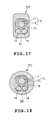
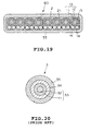
- a protection jacket using ultraviolet curing resin can be applied around the aforementioned various embodiments of the mono-fiber cord, or of the optical cord ribbon which is formed by bonding a plurality of mono-fiber cords in a side-by-side manner, for example as shown in FIGs. 17, 18 and 19 .
- this ultraviolet curing resin is used in many occasions as a coating material for optical fibers, and is of urethane-acrylic, which is cured in an extremely short time by irradiation of ultraviolet ray.
- This resin features that it can cope with a wide range of materials from soft coating layer to strong protection jacket by modifying its composition.
- Desolite TradeMark
- JSR Corporation whose head-office resides in Tokyo, Japan.
- the respective coating characteristics for the mono-fiber cord and that for the optical cord ribbon should be made different.
- the former is destroyed more easily than the latter.
- This material can be evaluated by a detected strength in a tension test. In other words, it is preferable to arrange such that the breaking strength of the latter is larger than that of the former.
- the mono-fiber cord 50 is shown in FIG. 17 , which is constructed by applying a protection jacket whose sectional surface is substantially rectangular around the optical fiber cord shown in FIG. 1 .
- a protection jacket whose sectional surface is substantially rectangular around the optical fiber cord shown in FIG. 1 .
- a protection jacket 52 of a circular sectional surface is used instead of the protection jacket 51.
- FIG. 19 there is shown an optical cord ribbon 60 which is configured by applying a protection jacket 53 around the bundling coat 21 of the optical cord ribbon 2 configured by bonding the longer sides of the mutually adjacent mono-fiber cord units 1.
- the protection jackets 51, 52 and 53 can be made of polyvinyl chloride, polyamide, polyethylene, and also of synthetic rubber such as isoprene, polychloroprene and butyl rubber. Further, the protection jackets 51, 52 and 53 can be made of the same material as those for the coat for mono-fiber cord 15, or of the bundling coat 21.
- the size of the mono-fiber cord can be minimized and lightened by putting a generally flat strength rod along the longitudinal direction of the coated fiber, for example one or more than one strength rods of high-elastic modulus as the strength member, the destruction thereof due to the bending force can be prevented.
- a generally flat strength rod along the longitudinal direction of the coated fiber for example one or more than one strength rods of high-elastic modulus as the strength member, the destruction thereof due to the bending force can be prevented.
- an optical cord ribbon is readily composed by combining a plurality of mono-fiber cords. Therefore, according to the optical cord ribbon of the present invention, since the strength rods are eccentrically located to one side, these strength rods can be readily removed when the optical fiber is to be connected. Still further, according to the optical cord ribbon of the present invention, the multi-mono cord conversion can be executed only by removing the outer sheath.
Landscapes
- Physics & Mathematics (AREA)
- General Physics & Mathematics (AREA)
- Optics & Photonics (AREA)
- Optical Fibers, Optical Fiber Cores, And Optical Fiber Bundles (AREA)
Claims (21)
- Câble en fibre optique de type monofibre, comprenant une fibre optique (13) gainée, composée d'une fibre optique (11) et d'une gaine de fibre (12), pour couvrir ladite fibre optique, et d'une enveloppe (15), couvrant ladite fibre optique (13) gainée et présentant une section transversale sensiblement rectangulaire, considérée perpendiculairement à la direction longitudinale de ladite enveloppe, ledit câble en fibre optique de type monofibre comprenant :une pluralité d'organes de renforcement (14), incorporés dans ladite enveloppe (15), caractérisé en ce que ladite pluralité d'organes de renforcement (14) sont situés le long d'un des côtés courts de la surface de section rectangulaire de ladite enveloppe (15), sont incorporés suivant la direction s'étendant longitudinalement de ladite fibre optique (13) gainée, sont situés en une relation symétrique par rapport à l'axe central de la section transversale rectangulaire de ladite enveloppe (15), ledit axe central étant parallèle aux côtés longs de la surface de section rectangulaire de ladite enveloppe (15), et situés à proximité de ladite fibre optique (13) gainée.
- Câble en fibre optique de type monofibre selon la revendication 1, dans lequel la surface de section de chaque organe de renforcement est un cercle.
- Câble en fibre optique de type monofibre selon la revendication 1, dans lequel la surface de section de chaque organe de renforcement est sensiblement rectangulaire.
- Câble en fibre optique de type monofibre selon la revendication 1, dans lequel la surface de section de chaque organe de renforcement est un ovale, s'étendant le long de ladite direction de petit côté dudit câble en fibre optique.
- Câble en fibre optique de type monofibre selon la revendication 1, dans lequel la surface de section de chaque organe de renforcement est un triangle sensiblement rectangle, dont l'hypoténuse ou côté oblique est situé(e) à proximité immédiate de ladite fibre optique gainée.
- Câble en fibre optique de type monofibre selon la revendication 1, dans lequel la surface de section de chaque organe de renforcement est sensiblement un pentagone ayant un côté situé à proximité immédiate de ladite fibre optique gainée.
- Câble en fibre optique de type monofibre selon la revendication 1, dans lequel ladite pluralité d'organes de renforcement sont composés d'une tige de renfort (22), située sur l'axe central de ladite enveloppe prévue pour la fibre optique gainée, parallèlement à son côté long, et d'une paire de tiges de renforcement (20) ayant chacune un diamètre plus grand que celui de ladite tige de renfort et situées en une relation de symétrie par rapport à l'axe central, prenant en sandwich ladite tige de renfort.
- Câble en fibre optique de type monofibre selon l'une quelconque des revendications 1 à 7, comprenant en outre un enrobage de protection, revêtant ladite enveloppe (15).
- Câble en fibre optique de type monofibre selon la revendication 8, dans lequel la surface de section dudit enrobage de protection est circulaire, ou sensiblement carrée.
- Câble en fibre optique de type monofibre selon l'une quelconque des revendications 1 à 9, dans lequel ledit organe de renforcement comprend un revêtement coloré, à des fins d'identification.
- Câble en fibre optique de type monofibre selon l'une quelconque des revendications 8 à 10, dans lequel ladite gaine de fibre et ledit enrobage de protection sont formés d'une résine polymérisant par exposition aux ultra-violets, de manière que ledit enrobage de protection soit plus facilement destructible que ladite gaine de fibre.
- Câble en fibre optique de type monofibre selon la revendication 8, dans lequel ledit enrobage de protection est composé de résine synthétique différente de ladite gaine utilisée pour la fibre optique gainée.
- Câble optique en nappe, comprenant une pluralité de câbles (1) en fibre optique de type monofibre et un gainage de mise en faisceaux (21), pour gainer solidairement ladite pluralité de câbles en fibre optique de type monofibre, dans lequel :chacune de la pluralité de câbles (1) en fibre optique de type monofibre comprend en outre :dans lequel ladite pluralité d'organes de renforcement (14) sont situés le long d'un des côtés courts de la surface de section rectangulaire de ladite enveloppe (15), sont incorporés suivant la direction s'étendant longitudinalement de ladite fibre optique (13) gainée, sont situés en une relation symétrique par rapport à l'axe central de la section transversale rectangulaire de ladite enveloppe (15), ledit axe central étant parallèle aux côtés longs de la surface de section rectangulaire de ladite enveloppe (15), et situés à proximité de ladite fibre optique (13) gainée,une fibre optique (13) gainée, composée d'une fibre optique (11) et d'une gaine de fibre (12), pour couvrir ladite fibre optique ;une enveloppe (15), couvrant ladite fibre optique (13) gainée et présentant une section transversale sensiblement rectangulaire, considérée perpendiculairement à la direction longitudinale de ladite enveloppe ; etune pluralité d'organes de renforcement (14), incorporés dans ladite enveloppe (15),
et ledit gainage de mise en faisceaux (21), est appliqué pour gainer solidairement ladite pluralité de câbles (1) en fibre optique de type monofibre, les côtés longs des câbles en fibre de type monofibre adjacents étant aboutés les uns les autres, et lesdits organes de renforcement (14) sont alignés côte-à-côte. - Câble optique en nappe selon la revendication 13, dans lequel la surface de section de chaque organe de renforcement est circulaire.
- Câble optique en nappe selon la revendication 13, dans lequel la surface de section de chaque organe de renforcement est sensiblement rectangulaire.
- Câble optique en nappe selon la revendication 13, dans lequel la surface de section de chaque organe de renforcement est de forme ovale, s'étendant le long de ladite direction de petit côté dudit câble en fibre optique.
- Câble optique en nappe selon la revendication 13, dans lequel la surface de section de chaque organe de renforcement est un triangle sensiblement rectangle, dont l'hypoténuse ou côté oblique est situé(e) à proximité immédiate de ladite fibre optique gainée.
- Câble optique en nappe selon la revendication 13, dans lequel la surface de section de chaque organe de renforcement est sensiblement un pentagone ayant un côté situé à proximité immédiate de ladite fibre optique gainée.
- Câble optique en nappe selon la revendication 13, dans lequel ladite pluralité d'organes de renforcement sont composés d'une tige de renfort, située sur l'axe central de ladite enveloppe prévue pour la fibre optique gainée, parallèlement à son côté long, et d'une paire de tiges de renforcement ayant chacune un diamètre plus grand que celui de ladite tige de renfort et situées en une relation de symétrie par rapport à l'axe central, prenant en sandwich ladite tige de renfort.
- Câble optique en nappe selon l'une quelconque des revendications 13 à 19, comprenant en outre un enrobage de protection, revêtant ladite enveloppe (15).
- Câble optique en nappe selon la revendication 20, dans lequel ledit enrobage de protection est formé de résine synthétique, différente de celle de ladite enveloppe prévue pour la fibre optique gainée.
Applications Claiming Priority (3)
| Application Number | Priority Date | Filing Date | Title |
|---|---|---|---|
| JP16127097 | 1997-06-18 | ||
| JP16127097 | 1997-06-18 | ||
| JP161270/97 | 1997-06-18 |
Publications (3)
| Publication Number | Publication Date |
|---|---|
| EP0886157A2 EP0886157A2 (fr) | 1998-12-23 |
| EP0886157A3 EP0886157A3 (fr) | 1999-10-06 |
| EP0886157B1 true EP0886157B1 (fr) | 2010-01-06 |
Family
ID=15731921
Family Applications (1)
| Application Number | Title | Priority Date | Filing Date |
|---|---|---|---|
| EP19980111067 Expired - Lifetime EP0886157B1 (fr) | 1997-06-18 | 1998-06-17 | Câble optique et câble optique en nappe |
Country Status (3)
| Country | Link |
|---|---|
| EP (1) | EP0886157B1 (fr) |
| CA (1) | CA2240754C (fr) |
| DE (1) | DE69841430D1 (fr) |
Families Citing this family (2)
| Publication number | Priority date | Publication date | Assignee | Title |
|---|---|---|---|---|
| EP1016887A1 (fr) * | 1998-12-31 | 2000-07-05 | Daewoo Telecom Ltd. | Faisceau optique dense avec une couche de tampon et câble optique composé avec un tel faisceau |
| EP1103833A1 (fr) * | 1999-11-25 | 2001-05-30 | Kerpenwerk GmbH & Co | Micro câble optique |
Family Cites Families (2)
| Publication number | Priority date | Publication date | Assignee | Title |
|---|---|---|---|---|
| JPS6086515A (ja) * | 1983-10-18 | 1985-05-16 | Junkosha Co Ltd | 光伝送条体及びこれを用いたフラツトケ−ブル |
| EP0856761A1 (fr) * | 1997-01-31 | 1998-08-05 | Fujikura Ltd. | Cordon optique, cable à ribbon utilisant le cordon et cable à ribbon avec une système de dérivation |
-
1998
- 1998-06-16 CA CA 2240754 patent/CA2240754C/fr not_active Expired - Fee Related
- 1998-06-17 EP EP19980111067 patent/EP0886157B1/fr not_active Expired - Lifetime
- 1998-06-17 DE DE69841430T patent/DE69841430D1/de not_active Expired - Lifetime
Also Published As
| Publication number | Publication date |
|---|---|
| CA2240754C (fr) | 2004-01-13 |
| DE69841430D1 (de) | 2010-02-25 |
| EP0886157A3 (fr) | 1999-10-06 |
| CA2240754A1 (fr) | 1998-12-18 |
| EP0886157A2 (fr) | 1998-12-23 |
Similar Documents
| Publication | Publication Date | Title |
|---|---|---|
| EP0922980B1 (fr) | Matrice combinée de medias de transmission | |
| US6115522A (en) | Optical fiber cord and optical cord ribbon | |
| CN101248382B (zh) | 光纤缆线及其形成方法 | |
| US5039195A (en) | Composite cable including portions having controlled flexural rigidities | |
| US6195489B1 (en) | Optical fiber cord, ribbon cord using the same and ribbon cord branch line | |
| US6839494B2 (en) | Dual stage fiber optic cable design | |
| EP3025174B1 (fr) | Ruban de fibre optique | |
| JPS63118110A (ja) | ケーブル組立体及びこれに屈曲部を形成する方法 | |
| JPH09218329A (ja) | 光ファイバマイクロケーブル | |
| CN1190469A (zh) | 带状光缆和它的制造方法 | |
| JP2004206048A (ja) | 光ファイバテープ心線及びその製造方法 | |
| JP2013109172A (ja) | 光ファイバユニット及び光ケーブル | |
| JPH08304675A (ja) | 光ファイバ心線 | |
| CA2240754C (fr) | Fibre optique et ruban de fibres optiques | |
| JP3773584B2 (ja) | 光ファイバーテープケーブル | |
| JP2003322727A (ja) | コネクタ付きケーブルおよび通線方法 | |
| JPS60185907A (ja) | 光フアイバ保護部材 | |
| JP4059825B2 (ja) | 光ドロップケーブル | |
| JPH095592A (ja) | 光ファイバコード | |
| JP2976819B2 (ja) | 光ファイバテープ心線の接続方法 | |
| JP2001042176A (ja) | 光ファイバケーブル | |
| JPS59208507A (ja) | 耐熱性多心光フアイバ心線 | |
| JPH11194244A (ja) | 光ファイバコードケーブル | |
| JP7155617B2 (ja) | 光ファイバケーブル | |
| JP2006003689A (ja) | 光ドロップケーブル |
Legal Events
| Date | Code | Title | Description |
|---|---|---|---|
| PUAI | Public reference made under article 153(3) epc to a published international application that has entered the european phase |
Free format text: ORIGINAL CODE: 0009012 |
|
| 17P | Request for examination filed |
Effective date: 19980715 |
|
| AK | Designated contracting states |
Kind code of ref document: A2 Designated state(s): DE FR GB IT |
|
| AX | Request for extension of the european patent |
Free format text: AL;LT;LV;MK;RO;SI |
|
| PUAL | Search report despatched |
Free format text: ORIGINAL CODE: 0009013 |
|
| AK | Designated contracting states |
Kind code of ref document: A3 Designated state(s): AT BE CH CY DE DK ES FI FR GB GR IE IT LI LU MC NL PT SE |
|
| AX | Request for extension of the european patent |
Free format text: AL;LT;LV;MK;RO;SI |
|
| AKX | Designation fees paid |
Free format text: DE FR GB IT |
|
| 17Q | First examination report despatched |
Effective date: 20040713 |
|
| GRAP | Despatch of communication of intention to grant a patent |
Free format text: ORIGINAL CODE: EPIDOSNIGR1 |
|
| GRAS | Grant fee paid |
Free format text: ORIGINAL CODE: EPIDOSNIGR3 |
|
| GRAA | (expected) grant |
Free format text: ORIGINAL CODE: 0009210 |
|
| RIN1 | Information on inventor provided before grant (corrected) |
Inventor name: NAKANISHI, ISAO,C/O NIPPON TELEGR. & TELEP. CORP Inventor name: URUNO, SHIGENORI,C/O NIPPON TELEGR. & TELEP. CORP Inventor name: TAKEMOTO, HAJIME,C/O NIPPON TELEGR. & TELEP. CORP Inventor name: TACHIKURA, MASAO, C/O NIPPON TELEGR. & TELEP. CORP |
|
| AK | Designated contracting states |
Kind code of ref document: B1 Designated state(s): DE FR GB IT |
|
| REG | Reference to a national code |
Ref country code: GB Ref legal event code: FG4D |
|
| REF | Corresponds to: |
Ref document number: 69841430 Country of ref document: DE Date of ref document: 20100225 Kind code of ref document: P |
|
| PLBE | No opposition filed within time limit |
Free format text: ORIGINAL CODE: 0009261 |
|
| STAA | Information on the status of an ep patent application or granted ep patent |
Free format text: STATUS: NO OPPOSITION FILED WITHIN TIME LIMIT |
|
| 26N | No opposition filed |
Effective date: 20101007 |
|
| PGFP | Annual fee paid to national office [announced via postgrant information from national office to epo] |
Ref country code: FR Payment date: 20120704 Year of fee payment: 15 Ref country code: GB Payment date: 20120629 Year of fee payment: 15 |
|
| PGFP | Annual fee paid to national office [announced via postgrant information from national office to epo] |
Ref country code: IT Payment date: 20120620 Year of fee payment: 15 |
|
| PGFP | Annual fee paid to national office [announced via postgrant information from national office to epo] |
Ref country code: DE Payment date: 20120731 Year of fee payment: 15 |
|
| GBPC | Gb: european patent ceased through non-payment of renewal fee |
Effective date: 20130617 |
|
| REG | Reference to a national code |
Ref country code: DE Ref legal event code: R119 Ref document number: 69841430 Country of ref document: DE Effective date: 20140101 |
|
| REG | Reference to a national code |
Ref country code: FR Ref legal event code: ST Effective date: 20140228 |
|
| PG25 | Lapsed in a contracting state [announced via postgrant information from national office to epo] |
Ref country code: DE Free format text: LAPSE BECAUSE OF NON-PAYMENT OF DUE FEES Effective date: 20140101 Ref country code: GB Free format text: LAPSE BECAUSE OF NON-PAYMENT OF DUE FEES Effective date: 20130617 |
|
| PG25 | Lapsed in a contracting state [announced via postgrant information from national office to epo] |
Ref country code: FR Free format text: LAPSE BECAUSE OF NON-PAYMENT OF DUE FEES Effective date: 20130701 Ref country code: IT Free format text: LAPSE BECAUSE OF NON-PAYMENT OF DUE FEES Effective date: 20130617 |