EP0886168A2 - Optischer Isolator und Wellenlängenmultiplexer-Modul mit integriertem optischen Isolator - Google Patents
Optischer Isolator und Wellenlängenmultiplexer-Modul mit integriertem optischen Isolator Download PDFInfo
- Publication number
- EP0886168A2 EP0886168A2 EP98440130A EP98440130A EP0886168A2 EP 0886168 A2 EP0886168 A2 EP 0886168A2 EP 98440130 A EP98440130 A EP 98440130A EP 98440130 A EP98440130 A EP 98440130A EP 0886168 A2 EP0886168 A2 EP 0886168A2
- Authority
- EP
- European Patent Office
- Prior art keywords
- optical
- wavelength
- optical isolator
- lens
- light
- Prior art date
- Legal status (The legal status is an assumption and is not a legal conclusion. Google has not performed a legal analysis and makes no representation as to the accuracy of the status listed.)
- Withdrawn
Links
- 230000003287 optical effect Effects 0.000 title claims description 73
- 239000000463 material Substances 0.000 claims abstract description 8
- 229910052710 silicon Inorganic materials 0.000 claims abstract description 5
- 239000010703 silicon Substances 0.000 claims abstract description 5
- 238000005530 etching Methods 0.000 claims abstract description 4
- 239000013307 optical fiber Substances 0.000 claims description 13
- 238000001125 extrusion Methods 0.000 abstract 2
- 230000005540 biological transmission Effects 0.000 description 5
- 238000000034 method Methods 0.000 description 5
- 239000013078 crystal Substances 0.000 description 4
- 239000000835 fiber Substances 0.000 description 4
- 238000004519 manufacturing process Methods 0.000 description 4
- XUIMIQQOPSSXEZ-UHFFFAOYSA-N Silicon Chemical compound [Si] XUIMIQQOPSSXEZ-UHFFFAOYSA-N 0.000 description 3
- 238000003384 imaging method Methods 0.000 description 3
- SVTBMSDMJJWYQN-UHFFFAOYSA-N 2-methylpentane-2,4-diol Chemical compound CC(O)CC(C)(C)O SVTBMSDMJJWYQN-UHFFFAOYSA-N 0.000 description 2
- 238000010276 construction Methods 0.000 description 2
- 239000012212 insulator Substances 0.000 description 2
- 238000003754 machining Methods 0.000 description 2
- 239000004033 plastic Substances 0.000 description 2
- 229920003023 plastic Polymers 0.000 description 2
- 230000010287 polarization Effects 0.000 description 2
- 238000004026 adhesive bonding Methods 0.000 description 1
- 239000000919 ceramic Substances 0.000 description 1
- 230000008878 coupling Effects 0.000 description 1
- 238000010168 coupling process Methods 0.000 description 1
- 238000005859 coupling reaction Methods 0.000 description 1
- 230000000694 effects Effects 0.000 description 1
- 238000005516 engineering process Methods 0.000 description 1
- 230000007613 environmental effect Effects 0.000 description 1
- 238000001914 filtration Methods 0.000 description 1
- 230000001771 impaired effect Effects 0.000 description 1
- 238000001746 injection moulding Methods 0.000 description 1
- 238000009434 installation Methods 0.000 description 1
- 238000002955 isolation Methods 0.000 description 1
- 238000005086 pumping Methods 0.000 description 1
- 239000004065 semiconductor Substances 0.000 description 1
- 230000007704 transition Effects 0.000 description 1
Images

Classifications
-
- G—PHYSICS
- G02—OPTICS
- G02B—OPTICAL ELEMENTS, SYSTEMS OR APPARATUS
- G02B6/00—Light guides; Structural details of arrangements comprising light guides and other optical elements, e.g. couplings
- G02B6/24—Coupling light guides
- G02B6/26—Optical coupling means
- G02B6/27—Optical coupling means with polarisation selective and adjusting means
- G02B6/2746—Optical coupling means with polarisation selective and adjusting means comprising non-reciprocal devices, e.g. isolators, FRM, circulators, quasi-isolators
Definitions
- the invention relates to an optical isolator according to the preamble of Claim 1.
- the invention further relates to a wavelength division multiplexer module according to claim 5 with an integrated optical isolator.
- Optical isolators are particularly needed in fiber optic data transmission systems. You should u. a. prevent interfaces from being reflected or scattered Light on optically active components such as laser diodes or optical Fiber amplifier hits and their function impaired.
- An optical isolator according to the preamble of claim 1 is known from EP-B-054 411.
- the optical isolator described there consists in essentially of two wedge-shaped plates made of optically birefringent Material and a Faraday rotator arranged between them.
- the Operation of this optical isolator is based on the fact that a parallel Light beam that strikes the insulator from one side, this on the leaves the other side as a parallel bundle of rays and about with the help of a lens, can be coupled into an optical fiber.
- Parallel Light on the other hand, which from this opposite side on the insulator hits, leaves the optical isolator as a divergent bundle of rays and can not be coupled back in, provided the optical fibers and the Imaging optics is arranged accordingly.
- the optical isolator described there is independent of the polarization of the incident light and therefore particularly suitable for applications in Data transmission systems with non-polarization preserving Standard fibers.
- very high demands on the location precision of those involved Imaging elements are provided in the known optical isolator a complex active adjustment of the individual components is required.
- Active adjustment in this context means that the components inserted into the optical beam path and in their installation position for so long be adjusted until the light beam has the desired properties.
- this is a very time-consuming handicraft, where one is under constant observation of a suitable measuring device by means of high-precision adjustment units adjusted. Because of the associated Optical isolators of this type are still very expensive and cost thus complicate the further spread of fiber optics Data transmission systems down to the end user area.
- optical isolator that consists of only a few individual parts that do not have to be actively adjusted.
- the optical isolator should have very small spatial dimensions and nevertheless be mechanically robust.
- the optical isolator should Enable the construction of an optically isolated wavelength division multiplexer module, which is made up of as few individual parts as possible and is inexpensive can be manufactured.
- the invention solves this problem with the help of that specified in claim 1 Features. Passive adjustment via stop edges eliminates this complex alignment of the individual components to each other. Furthermore are in the arrangement according to the invention no additional, the location of the components fixing individual optical components to one another (Brackets, guide pins etc.) required. As a result, the Build optical isolator according to the invention with only a very few components.
- the carrier used for fixing the position of the optical components can can also be used as a holding structure for other components.
- the Optical isolator according to the invention can thus be easily expand higher functional units.
- An example of one Functional unit is a wavelength division multiplexer module according to one of the Claims 5 to 7.
- Another embodiment of a wavelength division multiplexer module according to one of claims 8 or 9 comprises an additional adjusting element, which is also inserted into the recess. This adjustment element allows even with larger manufacturing tolerances an adjustment of the optical Isolators in a single adjustment step.
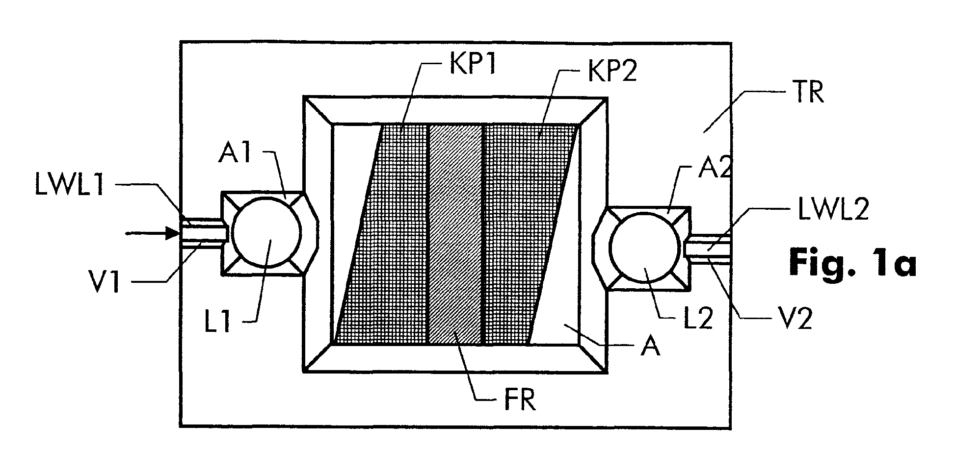
- FIG. 1a and 1b show an optical isolator according to the invention in Top view or in a side section.
- the optical isolator is on one Carrier TR constructed, which contains a recess A.
- the carrier consists of a microstructurable material. These include such materials understood that - with the help of suitable methods - to about a micrometer can be edited precisely. Such are possible Machining accuracy currently for example for semiconductor crystals, Plastics or ceramics.
- the carrier consists of a silicon crystal.
- the recess is then preferably wet-etched into the crystal. Such Etching processes are described in detail elsewhere, see e.g. B. EP-B1-0 418 423.
- the recess A In the recess A are two wedge-shaped plates made of optical birefringent material KP1 and KP2 as well as a Faraday rotator used.
- the individual components have those in Fig. 1a shown orientation to each other, d. H. the Faraday rotator is between the wedge-shaped plates and the plates themselves are oriented so that the arrangement of the three components is point symmetrical.
- the function the wedge-shaped plates and the Faraday rotator is detailed in the already EP-B-054 411 cited above.
- the illustrated embodiment are the undersides of the wedge-shaped plates and the bottom surface of the Recess A even, d. H. the wedge-shaped plates lie flat on the Bottom surface of the recess.
- Other designs of the floor area and the underside of the plate are also possible. So you can use Injection molding techniques made of plastic carrier, the bottom surface with Ribs are provided. Wear the upward facing edges of these ribs then the wedge-shaped plates.
- the optical fibers LWL1 and LWL2 are in V-shaped recesses V1 and V2 inserted, whereby their position is precisely fixed.
- two ball lenses L1 and L2 are provided, which are immediately before the ends of the two optical fibers LWL1 and LWL2 are positioned.
- the adjustment the ball lenses L1 and L2 also take place in this embodiment passive via point stops.
- the lenses are pyramid-shaped Recesses A1 and A2 used. Instead of spherical lenses you can naturally also other lenses such as aspherical or cylindrical lenses be used.
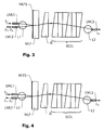
- Fig. 2 shows a particularly advantageous application example for the optical isolator according to the invention. It is a Wavelength division multiplexer module with integrated optical isolator. Such Wavelength division multiplexer modules are used, for example, in optical fiber amplifier systems. There is the task of pumping in to couple an optical fiber. The pump light has a different one Wavelength of light as the light guided in the fiber, which is the actual one Data transmission serves. Such wavelength division multiplexer modules are known for example from EP-A-0 723 170 and EP-A-492 850. In those there Wavelength division multiplexer modules are described as actual Multiplexer uses wavelength filters that have the property of light let a first wavelength pass through and light a second Reflect wavelength.
- the wavelength division multiplexer module according to FIG. 2 is based on the optical isolator sketched in FIGS. 1a and 1b.
- the optical isolator 2 has two stages for improving the optical isolation executed, d. H. it consists of two individual ones, one behind the other arranged optical isolators, each described in the above Are constructed in a way.
- the first optical isolator comprises the wedge-shaped ones Plates KP1 and KP2 as well as the Faraday rotator FR, the second optical Isolator the wedge-shaped plates KP21 and KP22 as well as the Faraday rotator FR2.
- the carrier TR is next to the two-stage optical isolator Wavelength filter WLF arranged.
- that is Wavelength filter inserted into a gap-shaped recess SP. This The recess is between the optical isolator and the spherical lens L1. If a silicon crystal is used as the carrier, then the Create recess SP, for example, by means of a saw cut.
- a first and a second optical waveguide LWL1 and LWL2 are located on the side of the arrangement facing the wavelength filter.
- a single lens serves as an imaging element for both optical waveguides. 3 is used to explain the beam path and the function of this arrangement.
- Light of a first wavelength ⁇ 1 is guided in the first optical waveguide LWL1. This light emerges from the opening of the first optical waveguide LWL1 and is collimated by the lens L1 arranged in front of it.
- This lens is preferably a spherical lens; however, the use of an aspherical lens is also conceivable.
- the collimated beam now hits the wavelength filter WLF.
- a layer sequence WLFS is applied, which effects the actual filtering.
- Light of the wavelength ⁇ 1 is reflected by the layer sequence WLFS.
- the reflected beam hits the lens L1 again and is focused by the latter onto the opening of the first optical waveguide LWL2.
- Light of a second wavelength ⁇ 2 which differs from the wavelength ⁇ 1 , is guided in the second optical waveguide LWL2. This light emerges from the opening of the optical waveguide LWL2 and is also collimated by the lens L1.
- the collimated beam strikes the wavelength filter WLF, which is transparent to light of this second wavelength ⁇ 2 .
- the light beam therefore reaches the adjusting element JE and from there to the components of the optical isolator ISOL.
- the beam is focused by the lens L2 onto the opening of a third optical waveguide LWL3.
- the light of the second wavelength ⁇ 2 does not emerge from the second optical fiber LWL2, but from the third optical fiber LWL3.
- the beam path for this is shown in FIG. 4.
- the optical isolator must be installed with the opposite direction of passage.
- the light of the second wavelength ⁇ 2 now takes the opposite path, ie it first passes through the optical isolator ISOL and then passes through the wavelength filter WLF.
- FIGS 4 show wavelength division multiplexer module without active adjustment steps being constructed.
- U. with certain materials and Machining methods cannot be avoided for cost reasons that Manufacturing tolerances occur that ensure proper functioning of the optical Isolators can affect.
- an additional one Take the adjusting element JE into the recess A.
- the adjusting element JE lies in the beam path of the optical isolator and is at least in one Spatially arranged.
- the shape of the adjusting element JE is also to be chosen so that when the adjustment element moves Beam path changes. The one shown in FIGS.
- the adjusting element JE is wedge-shaped and can be shift both in the direction of the optical axis and perpendicular to it. This allows adjustment of the optical isolator in just one Carry out adjustment step.
- the individual Components permanently fixed, for example by gluing.
- the wearer can use the Components are installed in a suitable housing.
- the wavelength division multiplexer module described here requires very little few components, resulting in low manufacturing costs with high Let reliability be realized.
- An inventive Wavelength division multiplexer module is based on a silicon carrier built on an area of only 3x7 mm and is therefore in the Compared to known wavelength division multiplexer modules much smaller. Since the structure of the module is essentially only in the provision of the Carrier and then inserting the components, especially with regard to the rapid development of etching technology and Micromechanics, expect an inexpensive series production of this Wavelength division multiplexer modules will soon be possible.
Landscapes
- Physics & Mathematics (AREA)
- General Physics & Mathematics (AREA)
- Optics & Photonics (AREA)
- Optical Couplings Of Light Guides (AREA)
Abstract
Description
- Fig. 1a:
- Einen erfindungsgemäßen optischen Isolator nach Anspruch 1 in Draufsicht,
- Fig. 1b:
- Einen erfindungsgemäßen optischen Isolator nach Anspruch 1 in einem seitlichen Schnitt,
- Fig. 2:
- Ein erfindungsgemäßes Wellenlängenmultiplexer-Modul nach Anspruch 9 mit integriertem zweistufigen optischen Isolator in Draufsicht,
- Fig. 3:
- Strahlengang für ein in Fig. 2 dargestelltes Wellenlängenmultiplexer-Modul,
- Fig. 4:
- Strahlengang für ein in Fig. 2 dargestelltes Wellenlängenmultiplexer-Modul, bei dem der optische Isolator im Vergleich zu Fig. 3 eine entgegengesetzte Durchlaßrichtung hat.
Claims (9)
- Optischer Isolator mit zwei keilförmigen Platten (KP1, KP2) aus optisch doppelbrechendem Material und einem dazwischen angeordneten Faraday-Rotator (FR),
dadurch gekennzeichnet, daß die Platten und der Faraday-Rotator auf einem Träger (TR) angeordnet sind, der eine Ausnehmung (A) hat, und daß die keilförmigen Platten und der Faraday-Rotator in die Ausnehmung (A) so eingesetzt sind, daß diese über Anschläge passiv justiert sind. - Optischer Isolator nach Anspruch 1, bei dema) der Träger (TR) aus Silizium besteht,b) die Ausnehmung (A) im Träger eine ebene Bodenfläche hat,c) diese Ausnehmung durch Ätzen erzeugt istd) und die Anschläge als gerade Kanten ausgeführt sind.
- Optischer Isolator nach einem der vorhergehenden Ansprüche, der eine erste und eine zweite Linse (L1, L2) hat, zwischen denen die keilförmigen Platten (KP1, KP2) und der Faraday-Rotator (FR) angeordnet sind.
- Optischer Isolator nach einem der vorhergehenden Ansprüche, bei dem zwei zusätzliche keilförmige Platten (KP21, KP22 in Fig. 2) aus optisch doppelbrechendem Material und ein zusätzlicher Faraday-Rotator (FR2) in die Ausnehmung (A) so eingesetzt sind, daß diese zusätzlichen Bauteile (KP21, KP22, FR2) eine zweite optische Isolatorstufe bilden.
- Wellenlängenmultiplexer-Modul mit einem optischen Isolator nach Anspruch 3 und einem Wellenlängenfilter (WLF in Fig. 2), welches Licht einer ersten Wellenlänge reflektiert und Licht einer zweiten Wellenlänge hindurchtreten läßt.
- Wellenlängenmultiplexer-Modul nach Anspruch 5, bei dema) das Licht der ersten Wellenlänge aus einem ersten Lichtwellenleiter (LWL1 in Fig. 3) austritt und von einer ersten Linse (L1) kollimiert wird,b) dieser kollimierte Strahl auf das Wellenlängenfilter (WLF) trifft und dort reflektiert wird,c) der reflektierte Strahl auf die erste Linse (L1) trifft und von dort in einen zweiten Lichtwellenleiter (LWL2) eingekoppelt,d) und bei dem das Licht der zweiten Wellenlänge aus dem zweiten Lichtwellenleiter (LWL2) austritt, von der ersten Linse (L1) kollimiert wird, das Wellenlängenfilter (WLF) und den optischen Isolator (ISOL) durchtritt und von einer zweiten Linse (L2) so fokussiert wird, daß es in einen dritten Lichtwellenleiter (LWL3) einkoppelt.
- Wellenlängenmultiplexer-Modul nach Anspruch 5, bei dema) das Licht der ersten Wellenlänge aus einem ersten Lichtwellenleiter (LWL1 in Fig. 4) austritt und von einer ersten Linse (L1) kollimiert wird,b) dieser kollimierte Strahl auf das Wellenlängenfilter (WLF) trifft und dort reflektiert wird,c) der reflektierte Strahl auf die erste Linse (L1) trifft und von dort in einen zweiten Lichtwellenleiter (LWL2) eingekoppelt,d) und bei dem das Licht der zweiten Wellenlänge aus einem dritten Lichtwellenleiter (LWL3) austritt, von einer zweiten Linse (L2) kollimiert wird, den optischen Isolator (ISOL) und das Wellenlängenfilter (WLF) durchtritt und von der ersten Linse (L1) so fokussiert wird, daß es in den zweiten Lichtwellenleiter (LWL2) einkoppelt.
- Wellenlängenmultiplexer-Modul nach einem der Ansprüche 5 bis 7 mit einem optischen Justierelement (JE), welches in der Ausnehmung (A) im Träger (TR) in der Weise verschiebbar angeordnet ist, daß sich bei einer Verschiebung ein Lichtstrahl, welcher durch das optische Justierelement hindurchtritt, seine Richtung ändert.
- Wellenlängenmultiplexer-Modul nach Anspruch 8, bei dem das optische Justierelement (JE) keilförmig ist.
Applications Claiming Priority (2)
| Application Number | Priority Date | Filing Date | Title |
|---|---|---|---|
| DE19725720A DE19725720A1 (de) | 1997-06-18 | 1997-06-18 | Optischer Isolator und Wellenlängenmuliplexer-Modul mit integriertem optischen Isolator |
| DE19725720 | 1997-06-18 |
Publications (2)
| Publication Number | Publication Date |
|---|---|
| EP0886168A2 true EP0886168A2 (de) | 1998-12-23 |
| EP0886168A3 EP0886168A3 (de) | 2000-09-06 |
Family
ID=7832820
Family Applications (1)
| Application Number | Title | Priority Date | Filing Date |
|---|---|---|---|
| EP98440130A Withdrawn EP0886168A3 (de) | 1997-06-18 | 1998-06-17 | Optischer Isolator und Wellenlängenmultiplexer-Modul mit integriertem optischen Isolator |
Country Status (4)
| Country | Link |
|---|---|
| US (1) | US6081635A (de) |
| EP (1) | EP0886168A3 (de) |
| JP (1) | JPH1172748A (de) |
| DE (1) | DE19725720A1 (de) |
Families Citing this family (24)
| Publication number | Priority date | Publication date | Assignee | Title |
|---|---|---|---|---|
| US6430337B1 (en) * | 1998-09-03 | 2002-08-06 | Agere Systems Optoelectronics Guardian Corp. | Optical alignment system |
| US6249619B1 (en) * | 1998-09-17 | 2001-06-19 | Agere Systems Optoelectronics Guardian Corp. | Optical isolator |
| DE10041501A1 (de) * | 2000-08-24 | 2002-03-21 | Scc Special Comm Cables Gmbh | Planarer Lichtwellenleiter-DWDM-Multiplexer/Demultiplexer |
| US6555480B2 (en) | 2001-07-31 | 2003-04-29 | Hewlett-Packard Development Company, L.P. | Substrate with fluidic channel and method of manufacturing |
| US6981759B2 (en) * | 2002-04-30 | 2006-01-03 | Hewlett-Packard Development Company, Lp. | Substrate and method forming substrate for fluid ejection device |
| US6554403B1 (en) | 2002-04-30 | 2003-04-29 | Hewlett-Packard Development Company, L.P. | Substrate for fluid ejection device |
| GB2400183A (en) * | 2003-04-01 | 2004-10-06 | Agilent Technologies Inc | Mounting optic fibre and optical waveguide on substrate |
| US7511901B2 (en) * | 2003-06-30 | 2009-03-31 | Micha Zimmermann | Micro-optic alignment system |
| US6910758B2 (en) * | 2003-07-15 | 2005-06-28 | Hewlett-Packard Development Company, L.P. | Substrate and method of forming substrate for fluid ejection device |
| CN100405104C (zh) * | 2003-12-15 | 2008-07-23 | 中国科学院上海光学精密机械研究所 | 基于空间双折射元件的可调谐带通滤波器 |
| US7391561B2 (en) | 2005-07-29 | 2008-06-24 | Aculight Corporation | Fiber- or rod-based optical source featuring a large-core, rare-earth-doped photonic-crystal device for generation of high-power pulsed radiation and method |
| US7537395B2 (en) * | 2006-03-03 | 2009-05-26 | Lockheed Martin Corporation | Diode-laser-pump module with integrated signal ports for pumping amplifying fibers and method |
| US7768700B1 (en) | 2006-11-30 | 2010-08-03 | Lockheed Martin Corporation | Method and apparatus for optical gain fiber having segments of differing core sizes |
| US8179594B1 (en) | 2007-06-29 | 2012-05-15 | Lockheed Martin Corporation | Method and apparatus for spectral-beam combining of fanned-in laser beams with chromatic-dispersion compensation using a plurality of diffractive gratings |
| US8526110B1 (en) | 2009-02-17 | 2013-09-03 | Lockheed Martin Corporation | Spectral-beam combining for high-power fiber-ring-laser systems |
| JP5205602B2 (ja) * | 2009-09-24 | 2013-06-05 | 株式会社エス・エム・エムプレシジョン | インライン光アイソレータ |
| US8503840B2 (en) | 2010-08-23 | 2013-08-06 | Lockheed Martin Corporation | Optical-fiber array method and apparatus |
| US8441718B2 (en) * | 2009-11-23 | 2013-05-14 | Lockheed Martin Corporation | Spectrally beam combined laser system and method at eye-safer wavelengths |
| WO2011130131A1 (en) | 2010-04-12 | 2011-10-20 | Lockheed Martin Corporation | Beam diagnostics and feedback system and method for spectrally beam-combined lasers |
| US9366872B2 (en) | 2014-02-18 | 2016-06-14 | Lockheed Martin Corporation | Apparatus and method for fiber-laser output-beam shaping for spectral beam combination |
| WO2016201625A1 (zh) * | 2015-06-16 | 2016-12-22 | 华为技术有限公司 | 一种准直透镜以及包括其的光模块 |
| CN105572916A (zh) * | 2016-02-03 | 2016-05-11 | 深圳市镭神智能系统有限公司 | 一种光隔离器 |
| WO2018119791A1 (zh) * | 2016-12-28 | 2018-07-05 | 华为技术有限公司 | 一种发射光组件、光器件、光模块以及无源光网络系统 |
| CN114911083A (zh) * | 2021-02-07 | 2022-08-16 | 福州高意通讯有限公司 | 一种带宽高隔离度低插损的光隔离器 |
Family Cites Families (14)
| Publication number | Priority date | Publication date | Assignee | Title |
|---|---|---|---|---|
| JPS57100410A (en) * | 1980-12-15 | 1982-06-22 | Fujitsu Ltd | Optical isolator |
| DE58909602D1 (de) * | 1989-09-22 | 1996-03-21 | Siemens Ag | Verfahren zum anisotropen Ätzen von Silizium |
| JPH03164706A (ja) * | 1989-11-24 | 1991-07-16 | Fujitsu Ltd | 光モジュールの製造方法 |
| US5264392A (en) * | 1990-07-05 | 1993-11-23 | At&T Bell Laboratories | Fabrication technique for silicon-based optical subassemblies |
| US5237445A (en) * | 1990-11-30 | 1993-08-17 | Shimadzu Corporation | Optical isolator |
| US5082343A (en) * | 1990-12-20 | 1992-01-21 | At&T Bell Laboratories | Isolated optical coupler |
| JP3112212B2 (ja) * | 1993-02-17 | 2000-11-27 | 住友電気工業株式会社 | 光アイソレータ |
| EP0653661A1 (de) * | 1993-11-12 | 1995-05-17 | AT&T Corp. | Optischer Isolator mit verringerter Polarisationsmodendispersion |
| US5471340A (en) * | 1994-01-07 | 1995-11-28 | Jds Fitel Inc. | Reflective optical non-reciprocal devices |
| DE4431285C1 (de) * | 1994-09-02 | 1995-12-07 | Ant Nachrichtentech | Lasermodul |
| DE69520251D1 (de) * | 1994-10-11 | 2001-04-12 | Sumitomo Electric Industries | Optischer Isolator |
| US5555330A (en) * | 1994-12-21 | 1996-09-10 | E-Tek Dynamics, Inc. | Wavelength division multiplexed coupler with low crosstalk between channels and integrated coupler/isolator device |
| US5661835A (en) * | 1995-01-19 | 1997-08-26 | Sumitomo Electric Industries, Ltd. | Optical composite module and method of assembling the same |
| US5808793A (en) * | 1996-01-17 | 1998-09-15 | Hewlett-Packard Company | Low-cost compact optical isolators |
-
1997
- 1997-06-18 DE DE19725720A patent/DE19725720A1/de not_active Withdrawn
-
1998
- 1998-06-17 EP EP98440130A patent/EP0886168A3/de not_active Withdrawn
- 1998-06-18 US US09/099,094 patent/US6081635A/en not_active Expired - Lifetime
- 1998-06-18 JP JP10171884A patent/JPH1172748A/ja active Pending
Also Published As
| Publication number | Publication date |
|---|---|
| JPH1172748A (ja) | 1999-03-16 |
| US6081635A (en) | 2000-06-27 |
| DE19725720A1 (de) | 1998-12-24 |
| EP0886168A3 (de) | 2000-09-06 |
Similar Documents
| Publication | Publication Date | Title |
|---|---|---|
| EP0886168A2 (de) | Optischer Isolator und Wellenlängenmultiplexer-Modul mit integriertem optischen Isolator | |
| EP0942267B1 (de) | Spektrometer | |
| DE69533890T2 (de) | Filteroptische Muffe und optischer Koppler, hergestellt unter Verwendung der filteroptischen Muffe | |
| EP2120025A1 (de) | Optische Sensorvorrichtung zur Detektion von Umgebungslicht | |
| DE102013013071B3 (de) | Optischer Koppler | |
| WO2006047896A1 (de) | Faser-linsen-anordnung sowie linsen-array für eine solche faser-linsen-anordnung | |
| DE19711121B4 (de) | Verzweigende Lichtwellenleiteranordnung und verzweigendes Lichtwellenleiterarray | |
| DE69923883T2 (de) | 2 x 2 Faseroptischer Schalter | |
| DE10201127A1 (de) | Anordnung zum Ein- und/oder Auskoppeln optischer Signale mindestens eines optischen Datenkanals in bzw. aus einem Lichtwellenleiter | |
| EP0315270A2 (de) | Optisches Mehrtorelement mit einem akustooptischen Modulator | |
| DE69305697T2 (de) | Optisches Bauelement gekoppelt an eine lineare Anordnung von optischen Fasern | |
| EP1031052A1 (de) | Faseroptisches endstück | |
| DE19720619A1 (de) | Verfahren und Vorrichtung zum Multiplexen von übertragenen Lichtsignalen | |
| DE102023118609B4 (de) | Multilichtwellenleiterstecker sowie Lichtwellenleiterverbinder mit einem solchen | |
| WO2008022609A1 (de) | Optisches koppelelement | |
| EP1203252B1 (de) | Optische kopplungseinrichtung | |
| DE19520167B4 (de) | Verfahren und Vorrichtung zur opto-elektronischen Entfernungsmessung nach dem Laufzeitverfahren | |
| EP1124146B1 (de) | Optisches Spektrometer mit Lichtwellenleiter | |
| DE3929453C1 (en) | Fibre-Fabry-Perot interferometer - has slot in substrate enabling opposite regions to be moved w.r.t. V=shaped groove for optical fibres | |
| DE102016116410A1 (de) | Optisches system zur einkopplung von laserlicht in eine lichtleitfaser, insbesondere eine einmoden-faser und ein verfahren zur erhöhung einer einstellgenauigkeit eines fokus eines lichtstrahls | |
| EP0899592A1 (de) | Optischer Duplexer | |
| EP0416169A2 (de) | Vorrichtung zur Kopplung von Lasern, Dioden oder dergleichen mit lichtleitenden Fasern oder solchen Fasern untereinander | |
| EP1090319B1 (de) | Optisches kopplungselement | |
| DE2851654A1 (de) | Koppelelement zum auskoppeln eines lichtanteils aus einem optischen wellenleiter und wiedereinkoppeln desselben in einen abzweigenden optischen wellenleiter sowie verfahren zur herstellung des elements | |
| DE10127542A1 (de) | Kopplungsanordnung zur optischen Kopplung eines Lichtleiters an einen Lichtempfänger |
Legal Events
| Date | Code | Title | Description |
|---|---|---|---|
| PUAI | Public reference made under article 153(3) epc to a published international application that has entered the european phase |
Free format text: ORIGINAL CODE: 0009012 |
|
| AK | Designated contracting states |
Kind code of ref document: A2 Designated state(s): DE ES FR GB IT NL SE |
|
| AX | Request for extension of the european patent |
Free format text: AL;LT;LV;MK;RO;SI |
|
| RAP3 | Party data changed (applicant data changed or rights of an application transferred) |
Owner name: ALCATEL |
|
| PUAL | Search report despatched |
Free format text: ORIGINAL CODE: 0009013 |
|
| AK | Designated contracting states |
Kind code of ref document: A3 Designated state(s): AT BE CH CY DE DK ES FI FR GB GR IE IT LI LU MC NL PT SE |
|
| AX | Request for extension of the european patent |
Free format text: AL;LT;LV;MK;RO;SI |
|
| 17P | Request for examination filed |
Effective date: 20000816 |
|
| AKX | Designation fees paid |
Free format text: DE ES FR GB IT NL SE |
|
| RAP1 | Party data changed (applicant data changed or rights of an application transferred) |
Owner name: AVANEX CORPORATION |
|
| STAA | Information on the status of an ep patent application or granted ep patent |
Free format text: STATUS: THE APPLICATION HAS BEEN WITHDRAWN |
|
| 18W | Application withdrawn |
Effective date: 20040614 |