EP0886285A2 - Bistabile selbstnachstellende Betätigungseinrichtung - Google Patents
Bistabile selbstnachstellende Betätigungseinrichtung Download PDFInfo
- Publication number
- EP0886285A2 EP0886285A2 EP98110890A EP98110890A EP0886285A2 EP 0886285 A2 EP0886285 A2 EP 0886285A2 EP 98110890 A EP98110890 A EP 98110890A EP 98110890 A EP98110890 A EP 98110890A EP 0886285 A2 EP0886285 A2 EP 0886285A2
- Authority
- EP
- European Patent Office
- Prior art keywords
- bolt
- coil
- armature
- magnet
- pole frame
- Prior art date
- Legal status (The legal status is an assumption and is not a legal conclusion. Google has not performed a legal analysis and makes no representation as to the accuracy of the status listed.)
- Granted
Links
- 230000007246 mechanism Effects 0.000 title claims abstract description 26
- 230000004907 flux Effects 0.000 claims abstract 4
- 230000000717 retained effect Effects 0.000 claims description 3
- 230000000694 effects Effects 0.000 claims description 2
- 230000008878 coupling Effects 0.000 claims 1
- 238000010168 coupling process Methods 0.000 claims 1
- 238000005859 coupling reaction Methods 0.000 claims 1
- 238000000034 method Methods 0.000 claims 1
- 230000003472 neutralizing effect Effects 0.000 claims 1
- 239000000945 filler Substances 0.000 abstract description 11
- 239000000446 fuel Substances 0.000 abstract description 10
- 238000009434 installation Methods 0.000 abstract description 3
- 125000006850 spacer group Chemical group 0.000 description 8
- 238000004519 manufacturing process Methods 0.000 description 3
- 239000002184 metal Substances 0.000 description 2
- 230000006835 compression Effects 0.000 description 1
- 238000007906 compression Methods 0.000 description 1
- 239000004020 conductor Substances 0.000 description 1
- 230000000994 depressogenic effect Effects 0.000 description 1
- 230000005415 magnetization Effects 0.000 description 1
- 238000012986 modification Methods 0.000 description 1
- 230000004048 modification Effects 0.000 description 1
- 239000007787 solid Substances 0.000 description 1
Images


Classifications
-
- E—FIXED CONSTRUCTIONS
- E05—LOCKS; KEYS; WINDOW OR DOOR FITTINGS; SAFES
- E05B—LOCKS; ACCESSORIES THEREFOR; HANDCUFFS
- E05B47/00—Operating or controlling locks or other fastening devices by electric or magnetic means
- E05B47/02—Movement of the bolt by electromagnetic means; Adaptation of locks, latches, or parts thereof, for movement of the bolt by electromagnetic means
- E05B47/026—Movement of the bolt by electromagnetic means; Adaptation of locks, latches, or parts thereof, for movement of the bolt by electromagnetic means the bolt moving rectilinearly
-
- B—PERFORMING OPERATIONS; TRANSPORTING
- B60—VEHICLES IN GENERAL
- B60K—ARRANGEMENT OR MOUNTING OF PROPULSION UNITS OR OF TRANSMISSIONS IN VEHICLES; ARRANGEMENT OR MOUNTING OF PLURAL DIVERSE PRIME-MOVERS IN VEHICLES; AUXILIARY DRIVES FOR VEHICLES; INSTRUMENTATION OR DASHBOARDS FOR VEHICLES; ARRANGEMENTS IN CONNECTION WITH COOLING, AIR INTAKE, GAS EXHAUST OR FUEL SUPPLY OF PROPULSION UNITS IN VEHICLES
- B60K15/00—Arrangement in connection with fuel supply of combustion engines or other fuel consuming energy converters, e.g. fuel cells; Mounting or construction of fuel tanks
- B60K15/03—Fuel tanks
- B60K15/04—Tank inlets
- B60K15/05—Inlet covers
-
- E—FIXED CONSTRUCTIONS
- E05—LOCKS; KEYS; WINDOW OR DOOR FITTINGS; SAFES
- E05B—LOCKS; ACCESSORIES THEREFOR; HANDCUFFS
- E05B47/00—Operating or controlling locks or other fastening devices by electric or magnetic means
- E05B47/0001—Operating or controlling locks or other fastening devices by electric or magnetic means with electric actuators; Constructional features thereof
- E05B47/0002—Operating or controlling locks or other fastening devices by electric or magnetic means with electric actuators; Constructional features thereof with electromagnets
-
- E—FIXED CONSTRUCTIONS
- E05—LOCKS; KEYS; WINDOW OR DOOR FITTINGS; SAFES
- E05B—LOCKS; ACCESSORIES THEREFOR; HANDCUFFS
- E05B79/00—Mounting or connecting vehicle locks or parts thereof
- E05B79/10—Connections between movable lock parts
- E05B79/20—Connections between movable lock parts using flexible connections, e.g. Bowden cables
-
- E—FIXED CONSTRUCTIONS
- E05—LOCKS; KEYS; WINDOW OR DOOR FITTINGS; SAFES
- E05B—LOCKS; ACCESSORIES THEREFOR; HANDCUFFS
- E05B83/00—Vehicle locks specially adapted for particular types of wing or vehicle
- E05B83/28—Locks for glove compartments, console boxes, fuel inlet covers or the like
- E05B83/34—Locks for glove compartments, console boxes, fuel inlet covers or the like for fuel inlet covers essentially flush with the vehicle surface
-
- H—ELECTRICITY
- H01—ELECTRIC ELEMENTS
- H01F—MAGNETS; INDUCTANCES; TRANSFORMERS; SELECTION OF MATERIALS FOR THEIR MAGNETIC PROPERTIES
- H01F7/00—Magnets
- H01F7/06—Electromagnets; Actuators including electromagnets
- H01F7/08—Electromagnets; Actuators including electromagnets with armatures
- H01F7/16—Rectilinearly-movable armatures
- H01F7/1607—Armatures entering the winding
- H01F7/1615—Armatures or stationary parts of magnetic circuit having permanent magnet
-
- B—PERFORMING OPERATIONS; TRANSPORTING
- B60—VEHICLES IN GENERAL
- B60K—ARRANGEMENT OR MOUNTING OF PROPULSION UNITS OR OF TRANSMISSIONS IN VEHICLES; ARRANGEMENT OR MOUNTING OF PLURAL DIVERSE PRIME-MOVERS IN VEHICLES; AUXILIARY DRIVES FOR VEHICLES; INSTRUMENTATION OR DASHBOARDS FOR VEHICLES; ARRANGEMENTS IN CONNECTION WITH COOLING, AIR INTAKE, GAS EXHAUST OR FUEL SUPPLY OF PROPULSION UNITS IN VEHICLES
- B60K15/00—Arrangement in connection with fuel supply of combustion engines or other fuel consuming energy converters, e.g. fuel cells; Mounting or construction of fuel tanks
- B60K15/03—Fuel tanks
- B60K15/04—Tank inlets
- B60K15/05—Inlet covers
- B60K2015/0515—Arrangements for closing or opening of inlet cover
- B60K2015/0538—Arrangements for closing or opening of inlet cover with open or close mechanism automatically actuated
-
- E—FIXED CONSTRUCTIONS
- E05—LOCKS; KEYS; WINDOW OR DOOR FITTINGS; SAFES
- E05B—LOCKS; ACCESSORIES THEREFOR; HANDCUFFS
- E05B47/00—Operating or controlling locks or other fastening devices by electric or magnetic means
- E05B47/0001—Operating or controlling locks or other fastening devices by electric or magnetic means with electric actuators; Constructional features thereof
- E05B47/0002—Operating or controlling locks or other fastening devices by electric or magnetic means with electric actuators; Constructional features thereof with electromagnets
- E05B47/0003—Operating or controlling locks or other fastening devices by electric or magnetic means with electric actuators; Constructional features thereof with electromagnets having a movable core
- E05B47/0004—Operating or controlling locks or other fastening devices by electric or magnetic means with electric actuators; Constructional features thereof with electromagnets having a movable core said core being linearly movable
-
- H—ELECTRICITY
- H01—ELECTRIC ELEMENTS
- H01F—MAGNETS; INDUCTANCES; TRANSFORMERS; SELECTION OF MATERIALS FOR THEIR MAGNETIC PROPERTIES
- H01F7/00—Magnets
- H01F7/06—Electromagnets; Actuators including electromagnets
- H01F7/08—Electromagnets; Actuators including electromagnets with armatures
- H01F7/121—Guiding or setting position of armatures, e.g. retaining armatures in their end position
- H01F7/122—Guiding or setting position of armatures, e.g. retaining armatures in their end position by permanent magnets
Definitions
- the present invention relates to electrically operated actuator mechanisms and particularly relates to such mechanisms which employ an electromagnetic operator and which are suitable for use in automotive applications such as, for example, a locking/unlocking mechanism for a fuel filler access door.
- an actuator mechanism which is remotely electrically operated, and particularly suitable locking and unlocking for an automotive fuel filler access door, it has been found difficult to provide for latching or holding of the mechanism in the energized actuator or unlocked state without the need to maintain electrical power to the mechanism.
- an actuator mechanism is spring biased to the locked position in the electrically de-energized state and is actuated and unlocked by electrical energization, it is thus necessary to maintain power to the electrical operator in order to maintain the mechanism in the unlocked state.
- the electrical power necessary to overcome the bias spring force on the actuator bolt results in a prohibitively expensive electrical actuator where power is maintained to the actuator during the time that it is energized for unlocking.
- the present invention provides a solution to the above-described problem of enabling remote control of an electrically operating latching/unlatching mechanism such as one suitable for moving a bolt member against a striker for remotely locking and unlocking a door.
- the invention provides for remote control of an electromagnetically operated latching/unlatching mechanism having a bolt member moved in contact with a striker by a bias spring and unlocked or moved away from the striker by electrical energization of a solenoid.
- the operator includes a permanent magnet attached to a pole piece and coil which are slidably moveable on a base or housing. Upon energization the solenoid armature moves the bolt member to the unlocked position and maintains the mechanism in the unlocked position by force of the magnetic attraction. The electrical energization of the solenoid may then be discontinued and the bolt member is retained in the unlocked position without electrical power.
- the unlocking is accomplished by energizing the solenoid with electrical current flow in one direction in the coil such that the pole piece is magnetized in a manner complementing the permanent magnet to provide sufficient force to overcome the force of the bias spring and move the armature to unlock the mechanism.
- the permanent magnet Upon discontinuing of the electrical energization, the permanent magnet is sufficiently strong to retain the armature mechanism in the actuated or unlocking state.
- the magnetization of the pole piece members opposes the magnetic poles of the permanent magnet and neutralizes the magnetic attraction of the magnet thereby permitting the bias spring to return the bolt member to its locking position.
- the slidable mounting of the coil, pole piece bolt and magnet sub-assembly on the housing permits the bolt to be adjusted for the locked position so as to provide adequate stroke of the solenoid armature and bolt member upon electrical energization in a manner which can accommodate wide variation of the components encountered in the sheet metal assembly, particularly the variation encountered in the assembly of mass produced motor vehicles.
- the present invention thus provides a low cost, self-positioning electromagnetic operator for providing remote electrical locking and unlocking of a mechanism and is particularly suitable for locking and unlocking of an automotive fuel filler access door.
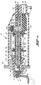
- the actuator assembly of the present invention is indicated generally at 10 and is shown as having a moveable bolt member 12 having a striker surface 14.
- the striker surface contacts the edge of the device to be locked indicated by reference numeral 18 which may be a hinged door as, for example, an automotive fuel filler access door.
- the door is moved or rammed against surface 14; and, the bolt is depressed rightwardly and slides along the surface of the door until engaging slot 16 in the door whereupon the bolt is spring biased into slot 16.
- the housing 20 has an end member 22 which is adapted to be mounted on a suitable supporting structure (not shown) as for example the automobile body upon which the access door 18 is hinged.
- Housing 20 has an electrical receptacle 24 formed in an end thereof opposite end member 22.
- Receptacle 24 has provided therein at least one electrical connector terminal adapted external electrical connection thereto as, for example, by a wiring harness connector.
- Housing 20 has disposed therein a generally tubular bobbin member 28 with a pair of spaced annular flanges 30, 32 provided thereon about which is wound a solenoid coil 34 of electrical conductor.
- Bobbin flange 32 has attached thereto an extension 36 which is anchored to housing 20 adjacent the electrical receptacle 24.
- the bobbin 28 has a tubular extension 38 extending axially outwardly from the flange 30. Referring to FIGS. 1 and 6 extension 38 has the end thereof received in and supported by counterbore 40 provided in a bolt guide member 41.
- An annular pole piece 42 is slidably received in the right hand end of the bobbin 28 and has a reduced diameter portion 44 thereof engaging an aperture 46 formed in a pole frame member 48.
- Member 48 has a generally right angular configuration with a flange 49 of the member 48 biased against the end of bobbin flange 32 by a compression spring 50 having one end registered against the member 48 with the opposite end registered against housing 20.
- a second pole frame member 52 extends from member 48 along the coil and over flange 30 and has a right angle flange portion 54 configured to slidably register against the surface of bobbin extension 38 via sliding surface 56 provided on the end of flange 54. It will be understood that the surface 56 is generally semicircular in shape to conform to the curved surface of extension 38.
- a pole frame spacer member 58 is provided between the flange 54 of pole frame member 52 and the right hand end of the bolt guide member 41.
- the spacer having a pair of oppositely disposed internal notches 59 into one of which is slidably received an orientation lug 60 provided on bolt member 62, which lug is registered in a slot 64 provided in the bolt guide member 41.
- Spacer 58 has a pair of oppositely disposed outwardly extending lugs 66 provided thereon which are adapted for engagement by portions of the bolt guide 41 as will hereinafter be described.
- FIG. 6 the groove 64 formed in the bore 40 of bolt guide member 41 is illustrated in greater detail. Referring to FIGS. 1, 4 and 6, it will be understood that a flange 70 provided on bolt 12 is sized for being slidably received in bore 40 in the bolt guide member 41.
- annular armature 72 is slidably disposed in the tubular extension 38 of the bobbin; and, armature 72 has a convolution or annular rib 74 formed on the end thereof remote from pole piece 42.
- the tubular extension 38 is received in the bore 40 of bolt guide member 41.
- the armature rib 74 is engaged in a groove 76 formed in the inner periphery of the bolt 12 on a cylindrical portion 78 thereof extending from flange 70 in a direction oppositely directed from the striker surface 14.
- the armature 72 is biased in a direction away from pole piece 42 by a spring 80 disposed therebetween.
- the engagement of the armature rib 74 in groove 76 of bolt extension 78 thus causes movement of the bolt 12 with movement of the armature 72.
- An emergency actuation cable 82 is received through a bore 84 formed in the housing; and, the cable extends through pole piece 42, armature 72 and outwardly through the left end of the armature with respect to FIG. 1.
- the end of the cable 82 has a retainer in the form of a ferrule 86 crimped over the end thereof to prevent withdrawal of the cable. It will be understood that leftward movement of the emergency pull- cable causes ferrule 86 to register against the left end of the armature 72; and, continued movement of the cable effects movement of the armature in a rightward direction until the right hand end of the armature 72 is in contact with the left end of pole piece 42. This rightward movement of the armature by cable 82 retracts bolt 12 from door aperture 16.
- a permanent magnet 88 is disposed between the end of pole frame member 48 and the end of pole frame member 52 and is secured therebetween by an annular clamping band 90, which in the presently preferred practice comprises heat shrink tubing.
- the bolt guide 41 has an annular outward extending flange 92 formed on one end thereof which flange has disposed on opposite sides thereof a pair of axially extending lugs 94, 96 each of which has a slot formed therein denoted respectively 98, 100 with integrally formed spring tabs 102, 104 extending therein.
- the spacer 58 is assembled over the extension 78 of the bolt and registered against the face of flange 70 with projection 60 of the spacer 58 aligned with one of the slots 59.
- the cable 82 is then assembled through armature 72; and, the rib 74 of the armature is engaged in groove 76 of the bolt 12.
- the spring 80 is received over the cable; and, the cable is fed through pole piece 42 and bore 84 in the housing to extend externally thereof for a suitable distance to provide the desired remote emergency actuation.
- the washer 58 is then assembled over portion 78 of the bolt and is registered against the face of flange 70 such that the extension 60 is aligned with a notch 59.
- the bolt 12 is then received in the bolt guide 41 with the projection 60 engaged in slot 64.
- the spring tabs 102, 104 are then engaged over suitable surfaces such as tabs 106, 108 provided on opposite sides of flange 54 of pole frame 52.
- the extension 66 on the spacer 58 extend through the slots 98, 100 formed in the projections 94, 96 on the bolt guide 41.
- the actuator assembly is illustrated in the locked condition in solid outline which bolt 12 has engaged the slot 16 in the door 18 to be locked; and, the door is shown in dashed outline in the open position.
- coil 34 is de-energized and the bias force of spring 80 is sufficient to move the armature 72 and bolt 12 leftward until the flange 70 on the bolt is registered against the end of bore 40 in guide 41.
- the door 18 is positioned with respect to housing 22 such that cover 52, spacer 58, pole frame member 52, magnet 88, pole frame piece 48 and pole piece 42 are moved leftward by the bias force of spring 50 to a position where the flange 92 on cover 62 has reached the leftward limit of its movement.
- the flange 49 of pole frame member 48 is registered against the right hand end face of bobbin flange 32 under the urging of spring 50.
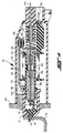
- the actuator assembly 10 is shown installed in a position where the door 18 is spaced slightly closer to end member 22; and, with the end of bolt guide 41 registered against door 18, the end flange 92 of guide 41 is moved further away from the right hand end of end member 22.
- the flange 49 of pole frame member 48 is spaced from the end face of bobbin flange 32 by a corresponding amount as shown by the space therebetween in FIG. 2.
- the pole frame, magnet and bolt guide as a subassembly is slidably moveable on the tubular extension 38 of the bobbin to accommodate during assembly, variations in the location of the door 18 with respect to the end 22 of the housing assembly.
- the actuator assembly 10 is shown in the coil energized or unlocked and latched condition in which the magnetic force of attraction of the solenoid coil 34 has added to the magnetic force of attraction of magnet 88 and caused the armature 72 to move rightward to contact the end of pole piece 42 and register thereagainst.
- the armature thus has moved bolt 12 rightward and disengaged the bolt from slot 16.
- the magnetic force of attraction of magnet 88 in the pole frame members 52, 48 is sufficient to hold the armature 72 against pole piece 42 and maintain the bolt 12 latched into the unlocked position permitting the door 18 to be moved from the position shown in FIG. 3 to the position shown in dashed outline in FIG. 3 for opening the door.
- the present invention thus provides a unique and novel electrically operated actuator assembly which is magnetically latched in the unlocked position by a permanent magnet upon coil energization by current flow in one direction. Upon re-energization with current flow in the opposite direction in the coil, the magnet is neutralized to permit the return spring to reengage the bolt.
- the subassembly of the pole frame, magnet and bolt is slidably moveable on the coil bobbin to permit the bolt guide to accommodate variations in location of the bolt guide with respect to the door or article to be engaged.
Landscapes
- Engineering & Computer Science (AREA)
- Physics & Mathematics (AREA)
- Electromagnetism (AREA)
- Life Sciences & Earth Sciences (AREA)
- Sustainable Development (AREA)
- Sustainable Energy (AREA)
- Chemical & Material Sciences (AREA)
- Combustion & Propulsion (AREA)
- Transportation (AREA)
- Mechanical Engineering (AREA)
- Power Engineering (AREA)
- Lock And Its Accessories (AREA)
Applications Claiming Priority (2)
| Application Number | Priority Date | Filing Date | Title |
|---|---|---|---|
| US878107 | 1997-06-18 | ||
| US08/878,107 US5936500A (en) | 1997-06-18 | 1997-06-18 | Bi-stable self-adjusting actuator mechanism |
Publications (3)
| Publication Number | Publication Date |
|---|---|
| EP0886285A2 true EP0886285A2 (de) | 1998-12-23 |
| EP0886285A3 EP0886285A3 (de) | 2000-04-19 |
| EP0886285B1 EP0886285B1 (de) | 2002-10-02 |
Family
ID=25371398
Family Applications (1)
| Application Number | Title | Priority Date | Filing Date |
|---|---|---|---|
| EP98110890A Expired - Lifetime EP0886285B1 (de) | 1997-06-18 | 1998-06-15 | Bistabile selbstnachstellende Betätigungseinrichtung |
Country Status (5)
| Country | Link |
|---|---|
| US (1) | US5936500A (de) |
| EP (1) | EP0886285B1 (de) |
| JP (1) | JPH1181767A (de) |
| DE (1) | DE69808380T2 (de) |
| ES (1) | ES2182183T3 (de) |
Cited By (4)
| Publication number | Priority date | Publication date | Assignee | Title |
|---|---|---|---|---|
| WO2001065573A3 (en) * | 2000-02-29 | 2002-03-21 | Tlx Technologies | Three position solenoid |
| GB2398826A (en) * | 2003-02-28 | 2004-09-01 | Pbt | An electrically actuated latch mechanism |
| GB2408998B (en) * | 2002-08-19 | 2006-04-12 | Neil Richard Hingston | Electric lock |
| EP2196605A1 (de) * | 2008-12-15 | 2010-06-16 | Adler S.A.S. | Elektromagnetisches Schloss |
Families Citing this family (8)
| Publication number | Priority date | Publication date | Assignee | Title |
|---|---|---|---|---|
| CN1112129C (zh) * | 1995-03-06 | 2003-06-25 | 株式会社片山 | 加工鱼肉和使用该加工鱼肉的鱼肉食品材料以及加工鱼肉的制造方法 |
| JP5580576B2 (ja) * | 2009-11-19 | 2014-08-27 | アイシン精機株式会社 | 車両用リッドロック装置 |
| US9051761B2 (en) | 2011-08-02 | 2015-06-09 | Kwikset Corporation | Manually driven electronic deadbolt assembly with fixed turnpiece |
| KR101439043B1 (ko) * | 2013-07-24 | 2014-09-05 | 현대자동차주식회사 | 케이블 이완 방지 기구 및 이를 구비한 연료 도어 장치 |
| CN105946571B (zh) * | 2016-05-04 | 2018-11-06 | 杰必机电配件(上海)有限公司 | 盖板控制装置及汽车 |
| US10118481B1 (en) * | 2017-06-14 | 2018-11-06 | Toyota Motor Engineering & Manufacturing North America, Inc. | Fuel housing assemblies having fuel nozzle boot deflector assemblies |
| CN110219526B (zh) * | 2019-05-30 | 2021-07-06 | 重庆常廷汽车零部件有限公司 | 用于加油或充电小门的具有锁销的锁结构 |
| KR102301733B1 (ko) * | 2020-08-14 | 2021-09-13 | 주식회사 이엔에스 | 배전반 도어를 원격으로 감시 및 제어하기 위한 인터록장치 |
Family Cites Families (11)
| Publication number | Priority date | Publication date | Assignee | Title |
|---|---|---|---|---|
| US3206656A (en) * | 1963-09-24 | 1965-09-14 | Daniel D Musgrave | Safety solenoid having a permanent magnet latching means |
| US3683239A (en) * | 1971-06-17 | 1972-08-08 | Oded E Sturman | Self-latching solenoid actuator |
| US4443775A (en) * | 1981-01-31 | 1984-04-17 | Shoketsu Kinzoku Kogyo Kabushiki Kaisha | Solenoid actuator |
| FR2573570B1 (fr) * | 1984-11-22 | 1988-05-27 | Merlin Gerin | Relais electromagnetique polarise a accrochage magnetique pour un declencheur d'un disjoncteur electrique |
| US4679017A (en) * | 1986-03-19 | 1987-07-07 | Synchro-Start Products, Inc. | Emergency manual actuation mechanism for a solenoid |
| US4758811A (en) * | 1987-02-13 | 1988-07-19 | Lectron Products, Inc. | Bistable solenoid actuator |
| US4947968A (en) * | 1989-05-01 | 1990-08-14 | Lectron Products, Inc. | Transmission mounted solenoid interlock device |
| US5076622A (en) * | 1990-07-25 | 1991-12-31 | Lectron Products, Inc. | Fuel filler latch assembly |
| US5044678A (en) * | 1990-07-25 | 1991-09-03 | Lectron Products, Inc. | Solenoid operated latch device with movable pole piece |
| US5563756A (en) * | 1994-03-18 | 1996-10-08 | Ignasiak; Martin C. | Resettable ground fault circuit interrupter |
| US5453724A (en) * | 1994-05-27 | 1995-09-26 | General Electric | Flux shifter assembly for circuit breaker accessories |
-
1997
- 1997-06-18 US US08/878,107 patent/US5936500A/en not_active Expired - Fee Related
-
1998
- 1998-06-15 ES ES98110890T patent/ES2182183T3/es not_active Expired - Lifetime
- 1998-06-15 EP EP98110890A patent/EP0886285B1/de not_active Expired - Lifetime
- 1998-06-15 DE DE69808380T patent/DE69808380T2/de not_active Expired - Fee Related
- 1998-06-18 JP JP17136398A patent/JPH1181767A/ja active Pending
Cited By (6)
| Publication number | Priority date | Publication date | Assignee | Title |
|---|---|---|---|---|
| WO2001065573A3 (en) * | 2000-02-29 | 2002-03-21 | Tlx Technologies | Three position solenoid |
| GB2408998B (en) * | 2002-08-19 | 2006-04-12 | Neil Richard Hingston | Electric lock |
| GB2398826A (en) * | 2003-02-28 | 2004-09-01 | Pbt | An electrically actuated latch mechanism |
| GB2398826B (en) * | 2003-02-28 | 2006-02-01 | Pbt | Electrically controllable latch mechanism |
| EP2196605A1 (de) * | 2008-12-15 | 2010-06-16 | Adler S.A.S. | Elektromagnetisches Schloss |
| FR2939827A1 (fr) * | 2008-12-15 | 2010-06-18 | Adler Sas | Verrou electromagnetique. |
Also Published As
| Publication number | Publication date |
|---|---|
| JPH1181767A (ja) | 1999-03-26 |
| US5936500A (en) | 1999-08-10 |
| DE69808380T2 (de) | 2003-07-10 |
| EP0886285B1 (de) | 2002-10-02 |
| ES2182183T3 (es) | 2003-03-01 |
| EP0886285A3 (de) | 2000-04-19 |
| DE69808380D1 (de) | 2002-11-07 |
Similar Documents
| Publication | Publication Date | Title |
|---|---|---|
| US5044678A (en) | Solenoid operated latch device with movable pole piece | |
| US5936500A (en) | Bi-stable self-adjusting actuator mechanism | |
| CA1306272C (en) | Bistable solenoid actuator | |
| US5076622A (en) | Fuel filler latch assembly | |
| US3664698A (en) | Electric actuating mechanism | |
| US20080164965A1 (en) | Adjustable solenoid | |
| US6241294B1 (en) | Motor vehicle door handle assembly | |
| US7532098B2 (en) | Actuator | |
| JPS5935335A (ja) | 電磁スイツチ | |
| CA2173275A1 (en) | Fuel filler door actuator assembly with integral kick-out spring | |
| US6914504B2 (en) | Electromagnetic switch for a starter | |
| CA2012055C (en) | Self-releasing deck lid latch | |
| CN1132303A (zh) | 汽车行李箱盖的锁和操纵机构 | |
| US4871989A (en) | Solenoid with manual actuation mechanism | |
| US5146196A (en) | Anti-rattle feature for solenoid | |
| JPS62297576A (ja) | 電磁弁 | |
| US5015980A (en) | Solenoid switch apparatus | |
| US6050623A (en) | Latchbolt assembly and method of sealing same | |
| CA1318793C (en) | Trunk lid lock with remote release | |
| WO1996042039A1 (en) | Electrically-operated latch | |
| US5382763A (en) | Electrical switch for automotive vehicle deck lid latches | |
| JP2008098404A (ja) | ソレノイド装置 | |
| US6918275B2 (en) | Manual internal release assembly for a vehicle decklid latch | |
| CN223527095U (zh) | 一种磁控保持继电器 | |
| JP3903222B2 (ja) | コントロールケーブルの中間ロック装置 |
Legal Events
| Date | Code | Title | Description |
|---|---|---|---|
| PUAI | Public reference made under article 153(3) epc to a published international application that has entered the european phase |
Free format text: ORIGINAL CODE: 0009012 |
|
| AK | Designated contracting states |
Kind code of ref document: A2 Designated state(s): DE ES FR GB IT |
|
| AX | Request for extension of the european patent |
Free format text: AL;LT;LV;MK;RO;SI |
|
| PUAL | Search report despatched |
Free format text: ORIGINAL CODE: 0009013 |
|
| AK | Designated contracting states |
Kind code of ref document: A3 Designated state(s): AT BE CH CY DE DK ES FI FR GB GR IE IT LI LU MC NL PT SE |
|
| AX | Request for extension of the european patent |
Free format text: AL;LT;LV;MK;RO;SI |
|
| RIC1 | Information provided on ipc code assigned before grant |
Free format text: 7H 01F 7/16 A, 7H 01F 7/122 B |
|
| 17P | Request for examination filed |
Effective date: 20000406 |
|
| 17Q | First examination report despatched |
Effective date: 20000707 |
|
| AKX | Designation fees paid |
Free format text: DE ES FR GB IT |
|
| GRAG | Despatch of communication of intention to grant |
Free format text: ORIGINAL CODE: EPIDOS AGRA |
|
| GRAG | Despatch of communication of intention to grant |
Free format text: ORIGINAL CODE: EPIDOS AGRA |
|
| GRAH | Despatch of communication of intention to grant a patent |
Free format text: ORIGINAL CODE: EPIDOS IGRA |
|
| GRAH | Despatch of communication of intention to grant a patent |
Free format text: ORIGINAL CODE: EPIDOS IGRA |
|
| GRAA | (expected) grant |
Free format text: ORIGINAL CODE: 0009210 |
|
| AK | Designated contracting states |
Kind code of ref document: B1 Designated state(s): DE ES FR GB IT |
|
| REG | Reference to a national code |
Ref country code: GB Ref legal event code: FG4D |
|
| REF | Corresponds to: |
Ref document number: 69808380 Country of ref document: DE Date of ref document: 20021107 |
|
| REG | Reference to a national code |
Ref country code: ES Ref legal event code: FG2A Ref document number: 2182183 Country of ref document: ES Kind code of ref document: T3 |
|
| ET | Fr: translation filed | ||
| PGFP | Annual fee paid to national office [announced via postgrant information from national office to epo] |
Ref country code: GB Payment date: 20030501 Year of fee payment: 6 |
|
| PGFP | Annual fee paid to national office [announced via postgrant information from national office to epo] |
Ref country code: FR Payment date: 20030602 Year of fee payment: 6 |
|
| PGFP | Annual fee paid to national office [announced via postgrant information from national office to epo] |
Ref country code: ES Payment date: 20030620 Year of fee payment: 6 |
|
| PGFP | Annual fee paid to national office [announced via postgrant information from national office to epo] |
Ref country code: DE Payment date: 20030630 Year of fee payment: 6 |
|
| PLBE | No opposition filed within time limit |
Free format text: ORIGINAL CODE: 0009261 |
|
| STAA | Information on the status of an ep patent application or granted ep patent |
Free format text: STATUS: NO OPPOSITION FILED WITHIN TIME LIMIT |
|
| 26N | No opposition filed |
Effective date: 20030703 |
|
| PG25 | Lapsed in a contracting state [announced via postgrant information from national office to epo] |
Ref country code: GB Free format text: LAPSE BECAUSE OF NON-PAYMENT OF DUE FEES Effective date: 20040615 |
|
| PG25 | Lapsed in a contracting state [announced via postgrant information from national office to epo] |
Ref country code: ES Free format text: LAPSE BECAUSE OF NON-PAYMENT OF DUE FEES Effective date: 20040616 |
|
| PG25 | Lapsed in a contracting state [announced via postgrant information from national office to epo] |
Ref country code: DE Free format text: LAPSE BECAUSE OF NON-PAYMENT OF DUE FEES Effective date: 20050101 |
|
| GBPC | Gb: european patent ceased through non-payment of renewal fee |
Effective date: 20040615 |
|
| PG25 | Lapsed in a contracting state [announced via postgrant information from national office to epo] |
Ref country code: FR Free format text: LAPSE BECAUSE OF NON-PAYMENT OF DUE FEES Effective date: 20050228 |
|
| REG | Reference to a national code |
Ref country code: FR Ref legal event code: ST |
|
| PG25 | Lapsed in a contracting state [announced via postgrant information from national office to epo] |
Ref country code: IT Free format text: LAPSE BECAUSE OF NON-PAYMENT OF DUE FEES;WARNING: LAPSES OF ITALIAN PATENTS WITH EFFECTIVE DATE BEFORE 2007 MAY HAVE OCCURRED AT ANY TIME BEFORE 2007. THE CORRECT EFFECTIVE DATE MAY BE DIFFERENT FROM THE ONE RECORDED. Effective date: 20050615 |
|
| REG | Reference to a national code |
Ref country code: ES Ref legal event code: FD2A Effective date: 20040616 |