EP0886289A2 - Commutateur électrique rotatif à poussoir - Google Patents
Commutateur électrique rotatif à poussoir Download PDFInfo
- Publication number
- EP0886289A2 EP0886289A2 EP98109626A EP98109626A EP0886289A2 EP 0886289 A2 EP0886289 A2 EP 0886289A2 EP 98109626 A EP98109626 A EP 98109626A EP 98109626 A EP98109626 A EP 98109626A EP 0886289 A2 EP0886289 A2 EP 0886289A2
- Authority
- EP
- European Patent Office
- Prior art keywords
- housing
- push switch
- actuator
- longitudinal axis
- switch according
- Prior art date
- Legal status (The legal status is an assumption and is not a legal conclusion. Google has not performed a legal analysis and makes no representation as to the accuracy of the status listed.)
- Granted
Links
Images
Classifications
-
- B—PERFORMING OPERATIONS; TRANSPORTING
- B60—VEHICLES IN GENERAL
- B60Q—ARRANGEMENT OF SIGNALLING OR LIGHTING DEVICES, THE MOUNTING OR SUPPORTING THEREOF OR CIRCUITS THEREFOR, FOR VEHICLES IN GENERAL
- B60Q1/00—Arrangement of optical signalling or lighting devices, the mounting or supporting thereof or circuits therefor
- B60Q1/02—Arrangement of optical signalling or lighting devices, the mounting or supporting thereof or circuits therefor the devices being primarily intended to illuminate the way ahead or to illuminate other areas of way or environments
- B60Q1/04—Arrangement of optical signalling or lighting devices, the mounting or supporting thereof or circuits therefor the devices being primarily intended to illuminate the way ahead or to illuminate other areas of way or environments the devices being headlights
- B60Q1/14—Arrangement of optical signalling or lighting devices, the mounting or supporting thereof or circuits therefor the devices being primarily intended to illuminate the way ahead or to illuminate other areas of way or environments the devices being headlights having dimming means
- B60Q1/1446—Arrangement of optical signalling or lighting devices, the mounting or supporting thereof or circuits therefor the devices being primarily intended to illuminate the way ahead or to illuminate other areas of way or environments the devices being headlights having dimming means controlled by mechanically actuated switches
- B60Q1/1453—Hand actuated switches
- B60Q1/1461—Multifunction switches for dimming headlights and controlling additional devices, e.g. for controlling direction indicating lights
- B60Q1/1469—Multifunction switches for dimming headlights and controlling additional devices, e.g. for controlling direction indicating lights controlled by or attached to a single lever, e.g. steering column stalk switches
- B60Q1/1476—Multifunction switches for dimming headlights and controlling additional devices, e.g. for controlling direction indicating lights controlled by or attached to a single lever, e.g. steering column stalk switches comprising switch controlling means located near the free end of the lever, e.g. press buttons, rotatable rings
-
- H—ELECTRICITY
- H01—ELECTRIC ELEMENTS
- H01H—ELECTRIC SWITCHES; RELAYS; SELECTORS; EMERGENCY PROTECTIVE DEVICES
- H01H25/00—Switches with compound movement of handle or other operating part
- H01H25/06—Operating part movable both angularly and rectilinearly, the rectilinear movement being along the axis of angular movement
Definitions
- the present invention is based on one according to the preamble of Main claim designed electrical rotary / push switch.
- Such electrical rotary / push switches are provided for one or several electrical circuit (s) by influencing the stationary in the housing and movably arranged to interrupt or close electrical contact parts conclude. It is thus possible for the user to Switching the connected electrical circuits on and off a variety of functions in a comfortable way on or off. Often times are the various functions via such electrical rotary / push switch the lighting system, wiper system, etc. of a motor vehicle.
- rotary / push switches are partially designed and made differently partly by adjusting the actuator radially and partly Part moved parallel to the longitudinal axis of the housing, but this leads to a correspondingly large radial dimension of the electrical switch.
- the movable electrical ones Contact parts arranged between two printed circuit boards, which are in the housing comprise stationary electrical contact parts.
- the present invention is therefore based on the object of a only actuator to be operated electrical rotary / push switch type mentioned in such a way that with high functional density and particularly compact design, all movable electrical contact parts in the essentially identical and designed to implement the various Switching functions are only kept displaceable parallel to the longitudinal axis of the housing are.
- the task is performed in the characterizing part of Main claim specified features solved.
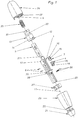
- a cup-shaped is formed on the free end region of the receiving body 1
- Functional element 10 rotatably mounted.
- the main surfaces of the Pot-shaped functional element 10 extend parallel to Longitudinal axis of housing 11.
- To that of the first half 2a of the actuator 2 facing main surface of the functional element 10 is a parallel to the Teeth 12 extending along the longitudinal axis 11 of the housing and having a plurality of teeth molded.
- the functional element 10 is positively connected via the toothing 12 or non-rotatably with a corresponding counter toothing 13 of the first half 2a of the actuator 2 in engagement.
- the functional element 10 is thus by direct coupling with a rotary adjustment of the actuator 2 in his different switching positions also adjusted.
- the functional element 10 From thrust adjustments of the Actuator 2, the functional element 10 remains unaffected because the Toothing 12 slidably parallel to the longitudinal axis 11 of the housing Counter toothing 13 is held.
- a control track 14 is formed in the jacket - shaped main surfaces of the Functional element 10.
- the control path 14 is as formed a slot breaking through the main surface wall and for Operation of a parallel to the longitudinal axis 11 of the housing on Receiving body 1 held.
- movable first contact part 3 Around To make this possible, the movable first contact part 3 has a slide carriage trained, an electrical contact element 18 fixed at one Main surface receiving carrier. To the other main surface of the Sliding carriage is integral with the control track 14 Control pin 15 integrally formed.
- control path 14 thus converts into an operative connection with the control pin 15 by its helical first Control path section the rotary movements of the Actuator 2 in translatory sliding movements for the movable first contact part 3 um.
- control pin 15 For the introduction of the control pin 15 into the control path 14 it has a short second one running parallel to the longitudinal axis 11 of the housing Control path section.
- the storage of the first half 2a of the actuator 2 is carried out by several molded onto the inner wall and running parallel to the longitudinal axis 11 of the housing Bearing webs 37 which slide on a bearing ring 19 of the receiving body 1 Plant come.
- the housing base body holding the receiving body 1 stationary is as tubular lever portion 22 formed.
- the receiving body 1 becomes fixed connection simply rotated with its molded mounting sleeve 23 and secured against thrust adjustment on the free end region of the lever section 22 snapped on.
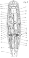
- the receiving body 1 that is functionally associated with the housing is essentially cone-shaped and takes - as already described - the Actuator 2 rotatably and thrust adjustable mounted.
- the second half 2b of the actuator 2 - in addition to those already measures described regarding the storage of the first half 2a - with its bottom facing away from the first half 2a rotatably on a slidably on the tubular lever portion 22 and the outer wall of the Receiving body 1 arranged sliding piece 24 mounted.
- the sliding piece 24 has for this purpose a guide groove 25 into which the underside of the second half 2b of the actuator 2 engage molded lugs 26.
- a locking cam ring is on the outer wall of the receiving body 1 27 slidably mounted parallel to the longitudinal axis 11 of the housing, but over appropriate holding means rotatable and immovable with the inner wall of the second half 2b of the actuator 2 is connected. So it will Sliding piece 24 only with a thrust adjustment of the actuator 2 in its different switching positions also adjusted, the locking cam ring 27 is, however both in a rotational and thrust adjustment of the actuator 2 in his different switch positions forcibly taken.
- the fact that the locking cam ring 27 is replaceable on the inner wall of the second half 2b of the actuator 2 is arranged, can be easily Way adjustment angle, number of switching positions, as well as locking and Switching positions to be reached by touch for different Realize rotary / push switch variants in a simple way.
- a movable electric is also on the two guide rails 17 second contact part 4 parallel to the longitudinal axis 11 of the housing Receiving body 1 held.
- the second contact part 4 corresponds in its Training in principle the first contact part 3.
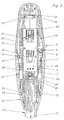
- Only the molded one Control pin 15 does not have a round, but a flat, rectangular Cross section on. This is only the case because the second contact element 4 is closed its actuation engages in a further control track 31, which consists of a variety parallel to the housing longitudinal axis 11 closely spaced Web 32 is formed.
- the webs 32 are interrupted like a groove at the same height, whereby the further concentric to the longitudinal axis 11 of the housing Control path 31 is created.
- the webs 32 are in part on the inner wall of the first half 2a and another part to the inner wall of the second half 2b of the actuator 2 integrally formed.
- the further control path 31 lies approximately on Height of the separation point of the two halves 2a, 2b of the actuator 2.
- Das Movable second contact part 4 is thus by direct coupling Thrust adjustments of the actuator 2 also adjusted, but remains because of concentric course of the further control path 31 by turning the Actuator 2 unaffected.
- the actuator 2 is groping in his brought about the three switch positions to be reached via the thrust adjustments.
- the contact parts are one Circuit board 5 summarized.
- the circuit board 5 lies - as well as further already described above - immovable in a pocket 7 of the Receiving body 1 fixed.
- One of the two main surfaces of the printed circuit board 5 comes while doing so on the receiving body 1 and the other of the two main surfaces the printed circuit board 5 is assigned in both movable contact parts 3, 4.
- the movable contact parts 3.4 reach through with their contact elements 18 in Receiving body 1 existing contact window and come to realize the different switching functions each with their contact elements 18 to the Circuit structure of the circuit board 5 to the system.
- the two movable contact parts 3, 4 via their guide grooves 16 each arranged between the two along the contact window Guide rails 17 on the receiving body 1 parallel to the longitudinal axis 11 of the housing kept movable.
- the printed circuit board 5 also extends their main surfaces parallel to the longitudinal axis 11. For the same reason the adjustment of the two movable contact parts 3, 4 is only parallel to the course of the longitudinal axis 11 of the housing, because as little installation space as possible is claimed.
- the actuator 2 can thus be operated comfortably in a simple manner be, the user through the clearly noticeable catch or the clearly noticeable pressure point is clearly shown that the adjusted Actuator 2 has assumed a defined switching position.
- the rotary / push switch is a functional component on the free end area of the Actuating lever of a steering column module attached, which Steering column module a higher-level control / functional unit of a Represents motor vehicle.
Landscapes
- Engineering & Computer Science (AREA)
- Mechanical Engineering (AREA)
- Switches With Compound Operations (AREA)
- Push-Button Switches (AREA)
Applications Claiming Priority (2)
| Application Number | Priority Date | Filing Date | Title |
|---|---|---|---|
| DE19723482 | 1997-06-04 | ||
| DE19723482A DE19723482C1 (de) | 1997-06-04 | 1997-06-04 | Elektrischer Dreh-/Schubschalter |
Publications (3)
| Publication Number | Publication Date |
|---|---|
| EP0886289A2 true EP0886289A2 (fr) | 1998-12-23 |
| EP0886289A3 EP0886289A3 (fr) | 2002-01-30 |
| EP0886289B1 EP0886289B1 (fr) | 2004-04-07 |
Family
ID=7831411
Family Applications (1)
| Application Number | Title | Priority Date | Filing Date |
|---|---|---|---|
| EP98109626A Expired - Lifetime EP0886289B1 (fr) | 1997-06-04 | 1998-05-27 | Commutateur électrique rotatif à poussoir |
Country Status (5)
| Country | Link |
|---|---|
| US (1) | US5939686A (fr) |
| EP (1) | EP0886289B1 (fr) |
| BR (1) | BR9804346A (fr) |
| DE (2) | DE19723482C1 (fr) |
| ES (1) | ES2218729T3 (fr) |
Families Citing this family (18)
| Publication number | Priority date | Publication date | Assignee | Title |
|---|---|---|---|---|
| JP2000067702A (ja) * | 1998-08-19 | 2000-03-03 | Alps Electric Co Ltd | 車載用ノブスイッチ装置 |
| US6403899B1 (en) * | 2000-03-23 | 2002-06-11 | Valeo Electrical Systems, Inc. | Vehicle fog lamp interlock switch apparatus |
| FR2816893B1 (fr) * | 2000-11-22 | 2003-05-30 | Valeo Electronique | Manette de commutateur de haut de colonne de direction de vehicule automobile a organe (s) de commande d'un appareil audio embarque et commutateur equipe d'une telle manette |
| US20020139648A1 (en) * | 2001-04-02 | 2002-10-03 | Hoskins Steven R. | Multifunctional lever stalk |
| US6617534B2 (en) * | 2001-05-07 | 2003-09-09 | Methode Electronics, Inc. | Combined detent plunger and moving contact |
| DE10206047C1 (de) * | 2002-02-14 | 2003-09-25 | Kostal Leopold Gmbh & Co Kg | Elektrische Schalteinrichtung |
| DE10220437A1 (de) * | 2002-05-08 | 2003-11-20 | Valeo Schalter & Sensoren Gmbh | Schalter, insbesondere Lenkstockschalter für Fahrzeug |
| JP2004022301A (ja) * | 2002-06-14 | 2004-01-22 | Tokai Rika Co Ltd | 一方向ロータリスイッチ |
| DE10242253A1 (de) | 2002-09-12 | 2004-03-25 | Leopold Kostal Gmbh & Co. Kg | Elektrische Schalteinrichtung |
| DE10247342A1 (de) * | 2002-10-10 | 2004-04-22 | Valeo Schalter Und Sensoren Gmbh | Elektrischer Dreh- und Schubschalter |
| FR2870634B1 (fr) * | 2004-05-21 | 2007-06-29 | Sc2N Sa | Dispositif de commutation pour vehicule automobile |
| DE102005012579A1 (de) * | 2005-03-18 | 2006-09-28 | Leopold Kostal Gmbh & Co. Kg | Kombinierter Druck- und Drehschalter für ein Kraftfahrzeug |
| JP2007080788A (ja) * | 2005-09-16 | 2007-03-29 | Alps Electric Co Ltd | 車載用ノブスイッチ装置 |
| JP2008192559A (ja) * | 2007-02-07 | 2008-08-21 | Alps Electric Co Ltd | 車載用ノブスイッチ |
| DE102010037531B4 (de) * | 2010-09-14 | 2016-04-28 | Elobau Gmbh & Co. Kg | Multifunktionaler Schalter für Kraftfahrzeuge |
| JP5975624B2 (ja) * | 2011-11-15 | 2016-08-23 | 株式会社ヴァレオジャパン | 車両用レバースイッチおよびその組み付け方法 |
| EP3128527A4 (fr) * | 2014-04-03 | 2017-11-15 | Kabushiki Kaisha Tokai-Rika-Denki-Seisakusho | Dispositif de commutation |
| CN113488346B (zh) * | 2021-06-29 | 2024-03-08 | 歌尔科技有限公司 | 开关组件、眼镜腿以及眼镜 |
Citations (1)
| Publication number | Priority date | Publication date | Assignee | Title |
|---|---|---|---|---|
| DE3802144C1 (en) | 1988-01-26 | 1989-06-15 | Leopold Kostal Gmbh & Co Kg, 5880 Luedenscheid, De | Electrical switch |
Family Cites Families (7)
| Publication number | Priority date | Publication date | Assignee | Title |
|---|---|---|---|---|
| DE2364278A1 (de) * | 1973-12-22 | 1975-06-26 | Daimler Benz Ag | Schalter, insbesondere kombi-schalter fuer die scheibenwisch- und -waschanlage eines kraftfahrzeuges |
| DE3740022C1 (en) * | 1987-11-26 | 1989-05-03 | Kostal Leopold Gmbh & Co Kg | Electrical switch |
| JPH0633630Y2 (ja) * | 1989-03-14 | 1994-08-31 | 株式会社東海理化電機製作所 | ノブ式スイッチ操作装置 |
| JPH0366133U (fr) * | 1989-10-31 | 1991-06-27 | ||
| GB9111811D0 (en) * | 1991-06-01 | 1991-07-24 | Ford New Holland Limited | Power take-off devices |
| JP2547127Y2 (ja) * | 1991-07-12 | 1997-09-10 | 株式会社東海理化電機製作所 | レバースイッチ装置 |
| US5691519A (en) * | 1993-03-25 | 1997-11-25 | Eaton Corporation | Electric switch, for use on automotive steering column switch |
-
1997
- 1997-06-04 DE DE19723482A patent/DE19723482C1/de not_active Expired - Fee Related
-
1998
- 1998-03-05 US US09/035,042 patent/US5939686A/en not_active Expired - Lifetime
- 1998-05-27 ES ES98109626T patent/ES2218729T3/es not_active Expired - Lifetime
- 1998-05-27 EP EP98109626A patent/EP0886289B1/fr not_active Expired - Lifetime
- 1998-05-27 DE DE59811130T patent/DE59811130D1/de not_active Expired - Lifetime
- 1998-06-08 BR BR9804346-3A patent/BR9804346A/pt not_active Application Discontinuation
Patent Citations (1)
| Publication number | Priority date | Publication date | Assignee | Title |
|---|---|---|---|---|
| DE3802144C1 (en) | 1988-01-26 | 1989-06-15 | Leopold Kostal Gmbh & Co Kg, 5880 Luedenscheid, De | Electrical switch |
Also Published As
| Publication number | Publication date |
|---|---|
| DE19723482C1 (de) | 1998-06-25 |
| EP0886289B1 (fr) | 2004-04-07 |
| BR9804346A (pt) | 1999-11-16 |
| EP0886289A3 (fr) | 2002-01-30 |
| DE59811130D1 (de) | 2004-05-13 |
| ES2218729T3 (es) | 2004-11-16 |
| US5939686A (en) | 1999-08-17 |
Similar Documents
| Publication | Publication Date | Title |
|---|---|---|
| EP0886289B1 (fr) | Commutateur électrique rotatif à poussoir | |
| DE19600657C1 (de) | Mehrstufiger elektrischer Wippenschalter | |
| DE69607599T2 (de) | Rückstellungseinrichtung für fahrrichtungsanzeige | |
| DE19726149C2 (de) | Schalteranordnung | |
| DE69127244T2 (de) | Schalter mit veränderlichem Widerstand | |
| DE3815883C2 (fr) | ||
| DE10027484C1 (de) | Kipp-Schiebe-Schalter | |
| EP0881707B1 (fr) | Commutateur électrique | |
| EP0460155B1 (fr) | Commutateur electrique, notamment commutateur de clignotant de vehicules a moteur | |
| DE19803693A1 (de) | Stockschalter, insbesondere Lenkstockschalter für Kraftfahrzeuge | |
| EP0827167B1 (fr) | Interrupteur électrique en particulier pour véhicules | |
| DE4240218C2 (de) | Schaltvorrichtung | |
| DE19722780C1 (de) | Elektrische Drehschaltereinheit | |
| DE3533872A1 (de) | Elektrischer schalter | |
| DE69329971T2 (de) | Schalterhebel für eine Lenksäule | |
| DE4334054C2 (de) | Elektrischer Schalter | |
| DE4137890C2 (de) | Elektrische Schalteranordnung | |
| DE19920547C1 (de) | Elektrischer Lenkstockschalter | |
| DE102011122405A1 (de) | Lenkstockschaltereinrichtung für ein Kraftfahrzeug und Kraftfahrzeug mit einer Lenkstockschaltereinrichtung | |
| EP1702796B1 (fr) | Bouton poussoir et commutateur rotatif combinés pour un véhicule | |
| EP1929494B1 (fr) | Interrupteur electrique | |
| DE4340276A1 (de) | Mehrstufiger Handschalter | |
| DE4409108A1 (de) | Elektrischer Vierwegeschalter | |
| EP0634764A1 (fr) | Module interrupteur à touche | |
| DE3821612C1 (en) | Electrical switch |
Legal Events
| Date | Code | Title | Description |
|---|---|---|---|
| PUAI | Public reference made under article 153(3) epc to a published international application that has entered the european phase |
Free format text: ORIGINAL CODE: 0009012 |
|
| AK | Designated contracting states |
Kind code of ref document: A2 Designated state(s): AT BE CH CY DE DK ES FI FR GB GR IE IT LI LU MC NL PT SE Kind code of ref document: A2 Designated state(s): DE ES FR GB IT SE |
|
| AX | Request for extension of the european patent |
Free format text: AL;LT;LV;MK;RO;SI |
|
| PUAL | Search report despatched |
Free format text: ORIGINAL CODE: 0009013 |
|
| AK | Designated contracting states |
Kind code of ref document: A3 Designated state(s): AT BE CH CY DE DK ES FI FR GB GR IE IT LI LU MC NL PT SE |
|
| AX | Request for extension of the european patent |
Free format text: AL;LT;LV;MK;RO;SI |
|
| RIC1 | Information provided on ipc code assigned before grant |
Free format text: 7H 01H 1/00 A, 7B 60Q 1/14 B |
|
| 17P | Request for examination filed |
Effective date: 20011221 |
|
| AKX | Designation fees paid |
Free format text: DE ES FR GB IT SE |
|
| GRAP | Despatch of communication of intention to grant a patent |
Free format text: ORIGINAL CODE: EPIDOSNIGR1 |
|
| GRAS | Grant fee paid |
Free format text: ORIGINAL CODE: EPIDOSNIGR3 |
|
| GRAA | (expected) grant |
Free format text: ORIGINAL CODE: 0009210 |
|
| AK | Designated contracting states |
Kind code of ref document: B1 Designated state(s): DE ES FR GB IT SE |
|
| REG | Reference to a national code |
Ref country code: GB Ref legal event code: FG4D Free format text: NOT ENGLISH |
|
| REF | Corresponds to: |
Ref document number: 59811130 Country of ref document: DE Date of ref document: 20040513 Kind code of ref document: P |
|
| REG | Reference to a national code |
Ref country code: IE Ref legal event code: FG4D Free format text: GERMAN |
|
| GBT | Gb: translation of ep patent filed (gb section 77(6)(a)/1977) |
Effective date: 20040603 |
|
| PG25 | Lapsed in a contracting state [announced via postgrant information from national office to epo] |
Ref country code: SE Free format text: LAPSE BECAUSE OF FAILURE TO SUBMIT A TRANSLATION OF THE DESCRIPTION OR TO PAY THE FEE WITHIN THE PRESCRIBED TIME-LIMIT Effective date: 20040707 |
|
| REG | Reference to a national code |
Ref country code: ES Ref legal event code: FG2A Ref document number: 2218729 Country of ref document: ES Kind code of ref document: T3 |
|
| ET | Fr: translation filed | ||
| REG | Reference to a national code |
Ref country code: IE Ref legal event code: FD4D |
|
| PLBE | No opposition filed within time limit |
Free format text: ORIGINAL CODE: 0009261 |
|
| STAA | Information on the status of an ep patent application or granted ep patent |
Free format text: STATUS: NO OPPOSITION FILED WITHIN TIME LIMIT |
|
| 26N | No opposition filed |
Effective date: 20050110 |
|
| PGFP | Annual fee paid to national office [announced via postgrant information from national office to epo] |
Ref country code: ES Payment date: 20140319 Year of fee payment: 17 |
|
| PGFP | Annual fee paid to national office [announced via postgrant information from national office to epo] |
Ref country code: GB Payment date: 20140502 Year of fee payment: 17 |
|
| PGFP | Annual fee paid to national office [announced via postgrant information from national office to epo] |
Ref country code: FR Payment date: 20140502 Year of fee payment: 17 Ref country code: IT Payment date: 20140317 Year of fee payment: 17 Ref country code: DE Payment date: 20140502 Year of fee payment: 17 |
|
| REG | Reference to a national code |
Ref country code: DE Ref legal event code: R119 Ref document number: 59811130 Country of ref document: DE |
|
| GBPC | Gb: european patent ceased through non-payment of renewal fee |
Effective date: 20150527 |
|
| PG25 | Lapsed in a contracting state [announced via postgrant information from national office to epo] |
Ref country code: IT Free format text: LAPSE BECAUSE OF NON-PAYMENT OF DUE FEES Effective date: 20150527 |
|
| REG | Reference to a national code |
Ref country code: FR Ref legal event code: ST Effective date: 20160129 |
|
| PG25 | Lapsed in a contracting state [announced via postgrant information from national office to epo] |
Ref country code: GB Free format text: LAPSE BECAUSE OF NON-PAYMENT OF DUE FEES Effective date: 20150527 Ref country code: DE Free format text: LAPSE BECAUSE OF NON-PAYMENT OF DUE FEES Effective date: 20151201 |
|
| PG25 | Lapsed in a contracting state [announced via postgrant information from national office to epo] |
Ref country code: FR Free format text: LAPSE BECAUSE OF NON-PAYMENT OF DUE FEES Effective date: 20150601 |
|
| REG | Reference to a national code |
Ref country code: ES Ref legal event code: FD2A Effective date: 20160628 |
|
| PG25 | Lapsed in a contracting state [announced via postgrant information from national office to epo] |
Ref country code: ES Free format text: LAPSE BECAUSE OF NON-PAYMENT OF DUE FEES Effective date: 20150528 |