EP0886336B1 - Flache planare, breitbandige, weitabtastende phasengesteuerte Gruppenantenne unter Verwendung von übereinanderliegenden Scheibenstrahlern - Google Patents
Flache planare, breitbandige, weitabtastende phasengesteuerte Gruppenantenne unter Verwendung von übereinanderliegenden Scheibenstrahlern Download PDFInfo
- Publication number
- EP0886336B1 EP0886336B1 EP98304800A EP98304800A EP0886336B1 EP 0886336 B1 EP0886336 B1 EP 0886336B1 EP 98304800 A EP98304800 A EP 98304800A EP 98304800 A EP98304800 A EP 98304800A EP 0886336 B1 EP0886336 B1 EP 0886336B1
- Authority
- EP
- European Patent Office
- Prior art keywords
- dielectric
- antenna
- hybrid
- disc
- puck
- Prior art date
- Legal status (The legal status is an assumption and is not a legal conclusion. Google has not performed a legal analysis and makes no representation as to the accuracy of the status listed.)
- Expired - Lifetime
Links
Images


Classifications
-
- H—ELECTRICITY
- H01—ELECTRIC ELEMENTS
- H01Q—ANTENNAS, i.e. RADIO AERIALS
- H01Q21/00—Antenna arrays or systems
- H01Q21/06—Arrays of individually energised antenna units similarly polarised and spaced apart
- H01Q21/061—Two dimensional planar arrays
- H01Q21/065—Patch antenna array
-
- H—ELECTRICITY
- H01—ELECTRIC ELEMENTS
- H01Q—ANTENNAS, i.e. RADIO AERIALS
- H01Q5/00—Arrangements for simultaneous operation of antennas on two or more different wavebands, e.g. dual-band or multi-band arrangements
- H01Q5/30—Arrangements for providing operation on different wavebands
- H01Q5/378—Combination of fed elements with parasitic elements
-
- H—ELECTRICITY
- H01—ELECTRIC ELEMENTS
- H01Q—ANTENNAS, i.e. RADIO AERIALS
- H01Q9/00—Electrically-short antennas having dimensions not more than twice the operating wavelength and consisting of conductive active radiating elements
- H01Q9/04—Resonant antennas
- H01Q9/0407—Substantially flat resonant element parallel to ground plane, e.g. patch antenna
- H01Q9/0414—Substantially flat resonant element parallel to ground plane, e.g. patch antenna in a stacked or folded configuration
-
- H—ELECTRICITY
- H01—ELECTRIC ELEMENTS
- H01Q—ANTENNAS, i.e. RADIO AERIALS
- H01Q9/00—Electrically-short antennas having dimensions not more than twice the operating wavelength and consisting of conductive active radiating elements
- H01Q9/04—Resonant antennas
- H01Q9/0407—Substantially flat resonant element parallel to ground plane, e.g. patch antenna
- H01Q9/0428—Substantially flat resonant element parallel to ground plane, e.g. patch antenna radiating a circular polarised wave
- H01Q9/0435—Substantially flat resonant element parallel to ground plane, e.g. patch antenna radiating a circular polarised wave using two feed points
Definitions
- the present invention relates generally to phased array antennas, and more particularly, to planar, low profile phased array antennas employing stacked disc radiators.
- the present invention provides for a planar, low-profile, very wideband, wide-scan phased array antenna using stacked-disc radiators embedded in dielectric media.
- the phased array antenna has a rectangular arrangement of unit cells that each comprise a ground plane, and a lower dielectric puck comprising a high dielectric constant material disposed on the ground plane.
- An excitable disc is disposed within the perimeter of and on top of the lower dielectric puck.
- An upper dielectric puck comprising a low dielectric constant material that has a dielectric constant that is lower than that of the lower dielectric puck is disposed on the excitable disc.
- a parasitic disc is disposed within the perimeter of and on top of the upper dielectric puck.
- the unit cell surrounding the dielectric pucks comprises a dielectric material having a dielectric constant that is lower than that of the lower dielectric puck.
- a radome is disposed on top of the parasitic disc and the dielectric filler material. Two orthogonal pairs of excitation probes are coupled to the lower excitable disc.
- the polarization of the phased array antenna may be single linear polarization, dual linear polarization, or circular polarization depending on whether a single pair or two pairs of excitation probes are excited.
- the phased array antenna may include a flush-mounted radome as part of its aperture.
- the phased array antenna has a low profile, is very compact, and can be made rigid. Its planar nature makes it well-suited for conformal applications and for tile array architectures, in general.
- stacked-disc radiators are embedded inside dielectric media (with no air pockets), and the radome is an integral part of the antenna aperture.
- the entire antenna aperture of the phased array antenna is planar, has a low profile, and is well suited to be conformally mounted on the ground plane, all while maintaining its wideband, wide-scan performance.
- phased array antennas with dual linear or circular polarization are needed.
- the present invention provides for phased array antennas that meet the needs of these applications.
- the phased array antenna provides an octave-bandwidth performance with excellent scan and polarization behavior, the array is very compact, and has a low-profile, which are desirable characteristics of light-weight antennas.
- the array can be made rigid wherein it is filled with noncompressible dielectric materials, as is required in applications that must withstand very high pressure or shock loads, such as in a submarine environment.
- the present antenna can radiate with either dual-linear polarization, or both senses of circular polarization.
- the present phased array antenna is thus well-suited for use in submarine, satellite communication, airborne-related applications.
- Figs. I and 2 show partial side and top views, respectively, of a planar, low-profile, stacked-disc radiator phased array antenna 10 in accordance with the principles of the present invention. Spacings (dx and dy) between elements 19 or unit cells 19 are the same and the unit cells 19 are disposed in a rectangular lattice arrangement. There are two (upper and lower) cylindrical dielectric pucks 16, 12 in each unit cell 19.
- the lower dielectric puck 12 is made of a high dielectric constant (high-K) material, and has a diameter D H , dielectric constant ⁇ H , and a thickness t 1 .
- the lower dielectric puck 12 is disposed on a ground plane 11.
- An excitable disc 13 having diameter D 1 is printed on top of the high-K lower dielectric puck 12.
- the upper puck 16 is a low-K dielectric puck 16 having a diameter D L , dielectric constant ⁇ L , and a thickness t 2 .
- a parasitic disc 17 having diameter D 2 lies on top of the low-K dielectric puck 16.
- the low-K dielectric puck 16 is disposed on top of the high-K lower dielectric puck 12 and the excitable disc 13. Centers of the two dielectric pucks 16, 12 and the two discs 13, 17 are aligned.
- the remainder of the unit cell 19 surrounding the two dielectric pucks 16, 12 comprises a low-K dielectric filler material 26 having a dielectric constant ⁇ s .
- a radome 18 having a dielectric constant ⁇ r and thickness t r is disposed on top of the parasitic disc 17 and the dielectric filler material 26.
- the lower excitable disc 13 is excited by two pairs of excitation probes 14, arranged in orthogonal locations. The probe separation is S for each pair of excitation probes 14.
- Each pair of excitation probes 14 is fed by coaxial cables 15, with 180° phase reversal.
- the upper parasitic disc 17 is parasitically excited, and is not directly fed by the probes 14.
- the lower excitable disc 13 is tuned to operate at a lower frequency band, while the parasitic disc 17 is tuned to higher frequencies. Consequently, the operational bandwidth of the antenna 10 is extended to encompass the lower and higher frequency bands.
- the two pairs of excitation probes 14 provide dual-linear polarization and circular polarization capability. More particularly, the polarization of the phased array antenna 10 may be single linear polarization, dual linear polarization, or circular polarization depending on whether a single pair or two pairs of excitation probes 14 are excited.
- Fig. 3 shows a first exemplary embodiment of the present antenna 10 that operates over an octave band from 7 GHz to 14 GHz.
- the dielectric constant of the surrounding low-K filler material 26 is chosen to be the same as the dielectric constant of the low-K dielectric puck 16. This results in a simple planar geometry for the antenna 10. Exemplary parameters for the embodiment of the antenna 10 shown in Fig.
- Fig. 4 shows the different components used to construct an embodiment of the present antenna 10 fabricated as a 2 x 4 subarray.
- Fig. 4 shows the ground plane 11 at the right side of the figure.
- To the left of the ground plane 11 is shown a set of high-K lower dielectric pucks 12 looking through the ground plane 11 which shows the coaxial cables 15 which would protrude through the ground plane 11.
- the excitable discs 13 are not shown, but are disposed below the lower dielectric pucks 12 shown in Fig. 4.
- a layer of filler material 26 having openings 26a therein that surround the high-K lower dielectric pucks 12 is depicted to the left of the set of high-K lower dielectric pucks 12.
- the low-K dielectric pucks 16 shown in Figs. 1 and 3, for example, have been replaced by a single low-K dielectric layer 16a, which is depicted to the left of the layer of filler material 26.
- the radome 18 is depicted to the left of the low-K dielectric layer 16a, and has the parasitic discs 17 printed on its bottom surface which faces the upper surface of the low-K dielectric layer 16a.
- the predicted return loss of the radiation impedance in a broadside case for the embodiment of the antenna 10 Fig. 3 is shown in Fig. 5. From 7 GHz to 14 GHz, the return loss is below -10 dB. The mismatch is better then 3:1 VSWR within 45° scan coverage over a 7 to 14 GHz.
- a waveguide simulator was built to validate the predicted data. The validation data derived for the antenna 10 of Fig. 3 using the waveguide simulator is shown in Fig. 6.
- FIG. 7 A feeding arrangement for the antenna 10 of Fig. 3 that produces both senses of circular polarization is shown in Fig. 7.
- the four probes 14 of each disc antenna 10 are excited in phase sequence in the manner shown in Fig. 7. This may be achieved by feeding two orthogonal pairs of probes 14 using two 180° hybrids 32, 33 and combining the outputs with a 90° hybrid 31.
- the 90° hybrid 31 receives left hand circularly polarized (LHCP) and right hand circularly polarized (RHCP) excitation signals.
- LHCP left hand circularly polarized
- RHCP right hand circularly polarized
- 0° and 90° outputs of the 90° hybrid 31 are coupled to first and second 180° hybrids 32, 33, respectively.
- the 0° output of the 90° hybrid 31 feeds the first 180° hybrid 32, while the 90° output of the 90° hybrid 31 feeds the second 180° hybrid 33.
- 0° and 180° outputs of the first 180° hybrid 32 are coupled to probes 14 located at 0° and 180°, respectively.
- 0° and 180° outputs of the second 180° hybrid 33 are coupled to probes 14 located at 90° and 270°, respectively.
- a 5 x 5 test array antenna 10 was built to measure the element patterns.
- Fig. 8 shows a measured H-plane pattern at 9.0 GHz and
- Fig. 9 shows a measured axial ratio of a circular polarized element pattern at 9.0 GHz for the 5 x 5 test array antenna 10. These patterns indicate that the present phased array antenna 10 has very good scan and axial ratio performance.
- Figs. 10 and 11 show top and side views, respectively, of a second exemplary embodiment of the present antenna 10.
- There are four tuning or shorting pins 14a symmetrically disposed around the center of the lower dielectric puck 12 to connect to the ground plane 11. These shorting pins 14a increase E-plane scan coverage in the high end of the frequency band.
- Figs. 12 and 13 show top and side views, respectively, of a 2 x 2 subarray antenna 10 having a feed layer 20.
- the feed layer packaging 20 comprises multilayer stripline feed printed wiring board 21 having a plurality of stripline vias 25 that cooperatively extend therethrough.
- a plurality of connectors 23 have housings that are coupled to the ground plane 11, and have center pins 24 that are coupled to a lower layer of the multilayer stripline feed printed wiring board 21.
- Selected ones of the plurality of stripline vias 25 are coupled between the center pins 24 and the probes 14 of the antenna 10.
- the plurality of stripline vias 25 are used to transfer input signals from the center pins 24 to the respective probes 14 and lower excitable discs 13 of the antenna 10.
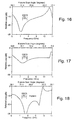
- Figs. 14 to 18 shows the predicted frequency performance for a large array antenna 10 using a plurality of the 2 x 2 subarrays shown in Figs. 12 and 13.
- Fig. 14 shows the return loss of the radiation impedance of the antenna 10 at broadside.
- Figs. 15-18 depict the return loss of the radiation impedance at H- and E-plane scan cases, respectively, of the antenna 10. Over the frequency band from 6.0 to 9.5 GHz range, this phased array antenna 10 has excellent aperture impedance match.
- planar antennas 10 have also been developed for 0.55" and 0.67" square lattices, as well as for several triangular lattice arrangements. All designs have the universal wideband, wide-scan properties of the planar stacked disc radiator antenna 10 of the present invention.
- planar, low profile phased array antennas employing a stacked disc radiator have been disclosed.
Landscapes
- Waveguide Aerials (AREA)
- Variable-Direction Aerials And Aerial Arrays (AREA)
Claims (8)
- Planare, phasengesteuerte Gruppenantenne (10) mit niedrigem Querschnitt, gekennzeichnet durch:eine rechteckige Anordnung von Einheitszellen (19), die jeweils aufweisen:eine Bodenebene (11);eine untere dielektrische Andruckscheibe (12), die ein Material mit hoher Dielektrizitätskonstante aufweist und auf der Bodenebene angeordnet ist;eine erregbare Scheibe (13), die innerhalb des Umfangs von und oben auf der unteren dielektrischen Andruckscheibe (12) angeordnet ist;eine obere dielektrische Andruckscheibe (16) mit einem Material mit geringer Dielektrizitätskonstante, wobei das Material eine Dielektrizitätskonstante hat, die geringer ist als jene der unteren dielektrischen Andruckscheibe, wobei die obere dielektrische Andruckscheibe (16) auf der erregbaren Scheibe (13) angeordnet ist;eine parasitäre Scheibe (17), die innerhalb des Umfangs von und oben auf der oberen dielektrischen Andruckscheibe angeordnet ist;und wobei die Einheitszelle, die die dielektrischen Andruckscheiben umgibt, ein dielektrisches Füllmaterial (26) mit einer Dielektrizitätskonstanten aufweist, die kleiner ist als jene der unteren dielektrischen Andruckscheibe;einen Radom (18), der auf der parasitären Scheibe und dem dielektrischen Füllmaterial angeordnet ist; undzwei orthogonale Paare von Erregungssonden (14), die mit der unteren erregbaren Scheibe gekoppelt sind.
- Antenne (10) nach Anspruch 1, wobei die Mitten der oberen und der unteren dielektrischen Andruckscheibe (16, 12) und der erregbaren und der parasitären Scheibe (13, 17) ausgerichtet sind.
- Antenne (10) nach Anspruch 1, wobei die Einheitszelle (19) die dielektrischen Andruckscheiben (16, 12) umgibt und gekennzeichnet ist durch ein dielektrisches Füllmaterial (26), das eine Dielektrizitätskonstante hat, die gleich jener der oberen dielektrischen Andruckscheibe ist.
- Antenne (10) nach Anspruch 1, wobei die obere und die untere dielektrische Andruckscheibe (16, 12) und die erregbare und die parasitäre Scheibe (13, 17) zylindrisch sind.
- Antenne (10) nach Anspruch 1, wobei jedes Paar der Erregungssonden (14) von einem separaten Koaxialkabel (15) mit 180° Phasenumkehr gespeist wird.
- Antenne (10) nach Anspruch 1, ferner gekennzeichnet durch eine Einspeisungs-Schicht (20), die gekennzeichnet ist durch:eine Mehrschicht-Leiterplatte (21) mit Streifenleitungs-Einspeisung, die eine Vielzahl von Streifenleitungs-Durchkontaktierungen (25), die sich durch die Leiterplatte erstrecken, und eine Vielzahl von Verbindern (23) aufweist, die Mittelstifte (24) besitzen, die mit den Streifenleitungs-Durchkontaktierungen (25) der Mehrschicht-Leiterplatte mit Streifenleitungseinspeisung gekoppelt sind, wobei die Verbinder mit jeweiligen der Paare von Erregungssonden (14) gekoppelt sind.
- Antenne (10) nach Anspruch 1, ferner gekennzeichnet durch:eine Einspeisungs-Anordnung, die eine Zirkularpolarisation sowohl erzeugt als auch erfasst, die durch eine 90°-Hybridschaltung (31) gekennzeichnet ist, die Ausgänge aufweist, die 180°-Hybridschaltungen (32, 33) speisen, deren Ausgangssignale mit den jeweiligen Sonden der orthogonalen Paare von Sonden (14) verbunden werden.
- Antenne (10) nach Anspruch 7, wobei die 90°-Hybridschaltung (31) nach links zirkularpolarisierte und nach rechts zirkularpolarisierte Erregungssignale empfängt, und wobei 0°- und 90°- Ausgangssignale der 90°-Hybridschaltung (31) der ersten und der zweiten 180°-Hybridschaltung (32, 33) zugeführt werden, wobei der 0°-Ausgang der 90°-Hybridschaltung (31) die erste 180°-Hybridschaltung (32) speist, während der 90°-Ausgang der 90°-Hybridschaltung die zweite 180°-Hybridschaltung (33) speist, der 0°- und 180°-Ausgang der ersten 180°-Hybridschaltung mit dem ersten Paar der Sonden (14) verbunden ist, und der 0°- und 180°-Ausgang der zweiten (18) 0°-Hybridschaltung mit dem zweiten Paar von Sonden (14) verbunden ist.
Applications Claiming Priority (2)
| Application Number | Priority Date | Filing Date | Title |
|---|---|---|---|
| US08/878,171 US5880694A (en) | 1997-06-18 | 1997-06-18 | Planar low profile, wideband, wide-scan phased array antenna using a stacked-disc radiator |
| US878171 | 1997-06-18 |
Publications (3)
| Publication Number | Publication Date |
|---|---|
| EP0886336A2 EP0886336A2 (de) | 1998-12-23 |
| EP0886336A3 EP0886336A3 (de) | 2000-04-05 |
| EP0886336B1 true EP0886336B1 (de) | 2003-10-01 |
Family
ID=25371526
Family Applications (1)
| Application Number | Title | Priority Date | Filing Date |
|---|---|---|---|
| EP98304800A Expired - Lifetime EP0886336B1 (de) | 1997-06-18 | 1998-06-17 | Flache planare, breitbandige, weitabtastende phasengesteuerte Gruppenantenne unter Verwendung von übereinanderliegenden Scheibenstrahlern |
Country Status (4)
| Country | Link |
|---|---|
| US (1) | US5880694A (de) |
| EP (1) | EP0886336B1 (de) |
| CA (1) | CA2240029C (de) |
| DE (1) | DE69818550T2 (de) |
Cited By (9)
| Publication number | Priority date | Publication date | Assignee | Title |
|---|---|---|---|---|
| WO2015142723A1 (en) * | 2014-03-17 | 2015-09-24 | Ubiquiti Networks, Inc. | Array antennas having a plurality of directional beams |
| US9293817B2 (en) | 2013-02-08 | 2016-03-22 | Ubiquiti Networks, Inc. | Stacked array antennas for high-speed wireless communication |
| US9397820B2 (en) | 2013-02-04 | 2016-07-19 | Ubiquiti Networks, Inc. | Agile duplexing wireless radio devices |
| US9490533B2 (en) | 2013-02-04 | 2016-11-08 | Ubiquiti Networks, Inc. | Dual receiver/transmitter radio devices with choke |
| US9496620B2 (en) | 2013-02-04 | 2016-11-15 | Ubiquiti Networks, Inc. | Radio system for long-range high-speed wireless communication |
| US9761954B2 (en) | 2015-10-09 | 2017-09-12 | Ubiquiti Networks, Inc. | Synchronized multiple-radio antenna systems and methods |
| US10164332B2 (en) | 2014-10-14 | 2018-12-25 | Ubiquiti Networks, Inc. | Multi-sector antennas |
| US10284268B2 (en) | 2015-02-23 | 2019-05-07 | Ubiquiti Networks, Inc. | Radio apparatuses for long-range communication of radio-frequency information |
| US11495891B2 (en) | 2019-11-08 | 2022-11-08 | Carrier Corporation | Microstrip patch antenna with increased bandwidth |
Families Citing this family (69)
| Publication number | Priority date | Publication date | Assignee | Title |
|---|---|---|---|---|
| US5745079A (en) * | 1996-06-28 | 1998-04-28 | Raytheon Company | Wide-band/dual-band stacked-disc radiators on stacked-dielectric posts phased array antenna |
| US6118066A (en) * | 1997-09-25 | 2000-09-12 | The United States Of America As Represented By The Secretary Of The Navy | Autonomous undersea platform |
| FR2778802B1 (fr) | 1998-05-15 | 2000-09-08 | Alsthom Cge Alcatel | Dispositif d'emission et de reception d'ondes hyperfrequences polarisees circulairement |
| US6114997A (en) * | 1998-05-27 | 2000-09-05 | Raytheon Company | Low-profile, integrated radiator tiles for wideband, dual-linear and circular-polarized phased array applications |
| US6157344A (en) * | 1999-02-05 | 2000-12-05 | Xertex Technologies, Inc. | Flat panel antenna |
| US6211824B1 (en) * | 1999-05-06 | 2001-04-03 | Raytheon Company | Microstrip patch antenna |
| GB2352091B (en) * | 1999-07-10 | 2003-09-17 | Alan Dick & Company Ltd | Patch antenna |
| ES2204035T3 (es) * | 1999-07-19 | 2004-04-16 | Raytheon Company | Antena de trayectos apilados multiples. |
| JP3472204B2 (ja) * | 1999-07-21 | 2003-12-02 | レイセオン・カンパニー | 広帯域の二重線形および円偏波されたフェイズドアレイ用の低プロフィールの集積された放射器タイル |
| FI112984B (fi) | 1999-10-20 | 2004-02-13 | Filtronic Lk Oy | Laitteen sisäinen antenni |
| WO2001086754A1 (en) * | 2000-05-05 | 2001-11-15 | Nokia Corporation | Base station of a communication network, preferably of a mobile telecommunication network |
| US20030117321A1 (en) * | 2001-07-07 | 2003-06-26 | Furse Cynthia M. | Embedded antennas for measuring the electrical properties of materials |
| US6549166B2 (en) * | 2001-08-22 | 2003-04-15 | The Boeing Company | Four-port patch antenna |
| US6778144B2 (en) | 2002-07-02 | 2004-08-17 | Raytheon Company | Antenna |
| EP1593178A1 (de) | 2003-02-01 | 2005-11-09 | Qinetiq Limited | Phasengesteuerte gruppenantenne und verfahren zur gegenseitigen kopplungssteuerung zwischen elementen |
| BG107620A (en) * | 2003-03-06 | 2004-09-30 | Raysat Cyprus Limited | Flat mobile aerial system |
| EP1624527B1 (de) * | 2003-04-24 | 2012-05-09 | Asahi Glass Company, Limited | Antenneneinrichtung |
| JP4149357B2 (ja) * | 2003-11-06 | 2008-09-10 | 株式会社ヨコオ | 複合アンテナ |
| US7298235B2 (en) * | 2004-01-13 | 2007-11-20 | Raytheon Company | Circuit board assembly and method of attaching a chip to a circuit board with a fillet bond not covering RF traces |
| US6982672B2 (en) * | 2004-03-08 | 2006-01-03 | Intel Corporation | Multi-band antenna and system for wireless local area network communications |
| US7102587B2 (en) * | 2004-06-15 | 2006-09-05 | Premark Rwp Holdings, Inc. | Embedded antenna connection method and system |
| US7209080B2 (en) * | 2004-07-01 | 2007-04-24 | Raytheon Co. | Multiple-port patch antenna |
| JP2006148728A (ja) * | 2004-11-24 | 2006-06-08 | Nec Corp | アンテナ装置およびこれを用いた無線通信装置 |
| US7126549B2 (en) * | 2004-12-29 | 2006-10-24 | Agc Automotive Americas R&D, Inc. | Slot coupling patch antenna |
| US7446710B2 (en) * | 2005-03-17 | 2008-11-04 | The Chinese University Of Hong Kong | Integrated LTCC mm-wave planar array antenna with low loss feeding network |
| US7258254B2 (en) * | 2005-03-24 | 2007-08-21 | Sonoco Development, Inc. | Dispensing end cap |
| US7304612B2 (en) * | 2005-08-10 | 2007-12-04 | Navini Networks, Inc. | Microstrip antenna with integral feed and antenna structures |
| US8018397B2 (en) * | 2005-12-30 | 2011-09-13 | Industrial Technology Research Institute | High dielectric antenna substrate and antenna thereof |
| TWI351130B (en) * | 2005-12-30 | 2011-10-21 | Ind Tech Res Inst | High dielectric antenna substrate and antenna thereof |
| DE102006027694B3 (de) * | 2006-06-14 | 2007-09-27 | Kathrein-Werke Kg | Mehrschichtige Antenne planarer Bauart |
| US7741999B2 (en) * | 2006-06-15 | 2010-06-22 | Kathrein-Werke Kg | Multilayer antenna of planar construction |
| US7498989B1 (en) | 2007-04-26 | 2009-03-03 | Lockheed Martin Corporation | Stacked-disk antenna element with wings, and array thereof |
| US8378893B2 (en) * | 2007-10-11 | 2013-02-19 | Raytheon Company | Patch antenna |
| US7973734B2 (en) * | 2007-10-31 | 2011-07-05 | Lockheed Martin Corporation | Apparatus and method for covering integrated antenna elements utilizing composite materials |
| DE102008019366B3 (de) * | 2008-04-17 | 2009-11-19 | Kathrein-Werke Kg | Mehrschichtige Antenne planarer Bauart |
| US8081118B2 (en) * | 2008-05-15 | 2011-12-20 | The Boeing Company | Phased array antenna radiator assembly and method of forming same |
| US7936306B2 (en) * | 2008-09-23 | 2011-05-03 | Kathrein-Werke Kg | Multilayer antenna arrangement |
| US8130149B2 (en) * | 2008-10-24 | 2012-03-06 | Lockheed Martin Corporation | Wideband strip fed patch antenna |
| US8159409B2 (en) * | 2009-01-20 | 2012-04-17 | Raytheon Company | Integrated patch antenna |
| US8274445B2 (en) * | 2009-06-08 | 2012-09-25 | Lockheed Martin Corporation | Planar array antenna having radome over protruding antenna elements |
| US9252491B2 (en) * | 2012-11-30 | 2016-02-02 | Taiwan Semiconductor Manufacturing Company, Ltd. | Embedding low-k materials in antennas |
| US9343816B2 (en) | 2013-04-09 | 2016-05-17 | Raytheon Company | Array antenna and related techniques |
| US9437929B2 (en) | 2014-01-15 | 2016-09-06 | Raytheon Company | Dual polarized array antenna with modular multi-balun board and associated methods |
| US9780458B2 (en) | 2015-10-13 | 2017-10-03 | Raytheon Company | Methods and apparatus for antenna having dual polarized radiating elements with enhanced heat dissipation |
| TWM527621U (zh) * | 2015-10-28 | 2016-08-21 | 正文科技股份有限公司 | 多極化天線元件 |
| US9806432B2 (en) | 2015-12-02 | 2017-10-31 | Raytheon Company | Dual-polarized wideband radiator with single-plane stripline feed |
| JP6577655B2 (ja) * | 2016-02-24 | 2019-09-18 | Necスペーステクノロジー株式会社 | ハイブリッド回路、給電回路、アンテナ装置、及び給電方法 |
| BR112018015094B1 (pt) * | 2016-07-15 | 2022-10-04 | Huawei Technologies Co., Ltd | Elemento de radiação, sistema que compreende o elemento de radiação e método para operar o elemento de radiação ou o sistema |
| US10581177B2 (en) * | 2016-12-15 | 2020-03-03 | Raytheon Company | High frequency polymer on metal radiator |
| US11088467B2 (en) | 2016-12-15 | 2021-08-10 | Raytheon Company | Printed wiring board with radiator and feed circuit |
| US10541461B2 (en) | 2016-12-16 | 2020-01-21 | Ratheon Company | Tile for an active electronically scanned array (AESA) |
| US10361485B2 (en) * | 2017-08-04 | 2019-07-23 | Raytheon Company | Tripole current loop radiating element with integrated circularly polarized feed |
| US10424847B2 (en) | 2017-09-08 | 2019-09-24 | Raytheon Company | Wideband dual-polarized current loop antenna element |
| US10547117B1 (en) | 2017-12-05 | 2020-01-28 | Unites States Of America As Represented By The Secretary Of The Air Force | Millimeter wave, wideband, wide scan phased array architecture for radiating circular polarization at high power levels |
| US10840573B2 (en) | 2017-12-05 | 2020-11-17 | The United States Of America, As Represented By The Secretary Of The Air Force | Linear-to-circular polarizers using cascaded sheet impedances and cascaded waveplates |
| WO2019116718A1 (ja) * | 2017-12-11 | 2019-06-20 | 株式会社村田製作所 | アンテナ付き基板、及び、アンテナモジュール |
| US11271311B2 (en) * | 2017-12-21 | 2022-03-08 | The Hong Kong University Of Science And Technology | Compact wideband integrated three-broadside-mode patch antenna |
| CN110011033B (zh) * | 2017-12-21 | 2020-09-11 | 香港科技大学 | 天线元件和天线结构 |
| US11139588B2 (en) * | 2018-04-11 | 2021-10-05 | Apple Inc. | Electronic device antenna arrays mounted against a dielectric layer |
| EP3912228B1 (de) * | 2019-01-17 | 2026-05-20 | Kyocera Int Inc | Antennenanordnung mit antennenelementen mit integrierten filtern |
| WO2021000083A1 (zh) * | 2019-06-29 | 2021-01-07 | 瑞声声学科技(深圳)有限公司 | 天线单元和天线阵列 |
| JP6917419B2 (ja) * | 2019-08-02 | 2021-08-11 | 原田工業株式会社 | 積層型パッチアンテナ |
| US11355862B1 (en) * | 2019-12-06 | 2022-06-07 | Lockheed Martin Corporation | Ruggedized antennas and systems and methods thereof |
| JP6876190B1 (ja) * | 2020-09-29 | 2021-05-26 | 株式会社ヨコオ | アンテナ、情報処理装置及び複合アンテナ装置 |
| EP4016735A1 (de) * | 2020-12-17 | 2022-06-22 | INTEL Corporation | Mehrbandige patch-antenne |
| DE102021113696B3 (de) * | 2021-05-27 | 2022-10-06 | Deutsches Zentrum für Luft- und Raumfahrt e.V. | Antennenelement zum Aussenden und Empfangen von dual-polarisierten elektromagnetischen Signalen |
| CN115084847A (zh) * | 2022-07-14 | 2022-09-20 | 西安航天天绘数据技术有限公司 | 一种抗干扰天线阵元装置 |
| CN115101930B (zh) * | 2022-07-15 | 2022-11-15 | 广东工业大学 | 边缘加载谐振枝节的双频卫星导航天线 |
| WO2025253660A1 (ja) * | 2024-06-06 | 2025-12-11 | 三菱電機株式会社 | 円偏波アンテナ装置 |
Family Cites Families (10)
| Publication number | Priority date | Publication date | Assignee | Title |
|---|---|---|---|---|
| US4623893A (en) * | 1983-12-06 | 1986-11-18 | State Of Israel, Ministry Of Defense, Rafael Armament & Development Authority | Microstrip antenna and antenna array |
| US4835538A (en) * | 1987-01-15 | 1989-05-30 | Ball Corporation | Three resonator parasitically coupled microstrip antenna array element |
| FR2623020B1 (fr) * | 1987-11-05 | 1990-02-16 | Alcatel Espace | Dispositif d'excitation d'un guide d'onde en polarisation circulaire par une antenne plane |
| US5006859A (en) * | 1990-03-28 | 1991-04-09 | Hughes Aircraft Company | Patch antenna with polarization uniformity control |
| US5210542A (en) * | 1991-07-03 | 1993-05-11 | Ball Corporation | Microstrip patch antenna structure |
| DE69229678T2 (de) * | 1991-10-28 | 2000-04-06 | Teledesic Llc, Kirkland | Satellitenkommunikationssystem |
| FR2706085B1 (fr) * | 1993-06-03 | 1995-07-07 | Alcatel Espace | Structure rayonnante multicouches à directivité variable. |
| US5777581A (en) * | 1995-12-07 | 1998-07-07 | Atlantic Aerospace Electronics Corporation | Tunable microstrip patch antennas |
| CA2206613C (en) * | 1996-05-31 | 2000-12-19 | Ushiodenki Kabushiki Kaisha | Process and device for bonding discs to one another |
| US5745079A (en) * | 1996-06-28 | 1998-04-28 | Raytheon Company | Wide-band/dual-band stacked-disc radiators on stacked-dielectric posts phased array antenna |
-
1997
- 1997-06-18 US US08/878,171 patent/US5880694A/en not_active Expired - Lifetime
-
1998
- 1998-06-10 CA CA002240029A patent/CA2240029C/en not_active Expired - Fee Related
- 1998-06-17 EP EP98304800A patent/EP0886336B1/de not_active Expired - Lifetime
- 1998-06-17 DE DE69818550T patent/DE69818550T2/de not_active Expired - Lifetime
Cited By (27)
| Publication number | Priority date | Publication date | Assignee | Title |
|---|---|---|---|---|
| US9397820B2 (en) | 2013-02-04 | 2016-07-19 | Ubiquiti Networks, Inc. | Agile duplexing wireless radio devices |
| US9496620B2 (en) | 2013-02-04 | 2016-11-15 | Ubiquiti Networks, Inc. | Radio system for long-range high-speed wireless communication |
| US9490533B2 (en) | 2013-02-04 | 2016-11-08 | Ubiquiti Networks, Inc. | Dual receiver/transmitter radio devices with choke |
| US9531067B2 (en) | 2013-02-08 | 2016-12-27 | Ubiquiti Networks, Inc. | Adjustable-tilt housing with flattened dome shape, array antenna, and bracket mount |
| US9293817B2 (en) | 2013-02-08 | 2016-03-22 | Ubiquiti Networks, Inc. | Stacked array antennas for high-speed wireless communication |
| US9368870B2 (en) | 2014-03-17 | 2016-06-14 | Ubiquiti Networks, Inc. | Methods of operating an access point using a plurality of directional beams |
| US9843096B2 (en) | 2014-03-17 | 2017-12-12 | Ubiquiti Networks, Inc. | Compact radio frequency lenses |
| US9912053B2 (en) | 2014-03-17 | 2018-03-06 | Ubiquiti Networks, Inc. | Array antennas having a plurality of directional beams |
| US11296407B2 (en) | 2014-03-17 | 2022-04-05 | Ubiqsiti Inc. | Array antennas having a plurality of directional beams |
| WO2015142723A1 (en) * | 2014-03-17 | 2015-09-24 | Ubiquiti Networks, Inc. | Array antennas having a plurality of directional beams |
| US10916844B2 (en) | 2014-03-17 | 2021-02-09 | Ubiquiti Inc. | Array antennas having a plurality of directional beams |
| US10770787B2 (en) | 2014-10-14 | 2020-09-08 | Ubiquiti Inc. | Multi-sector antennas |
| US11303016B2 (en) | 2014-10-14 | 2022-04-12 | Ubiquiti Inc. | Multi-sector antennas |
| US10164332B2 (en) | 2014-10-14 | 2018-12-25 | Ubiquiti Networks, Inc. | Multi-sector antennas |
| US10284268B2 (en) | 2015-02-23 | 2019-05-07 | Ubiquiti Networks, Inc. | Radio apparatuses for long-range communication of radio-frequency information |
| US10749581B2 (en) | 2015-02-23 | 2020-08-18 | Ubiquiti Inc. | Radio apparatuses for long-range communication of radio-frequency information |
| US11115089B2 (en) | 2015-02-23 | 2021-09-07 | Ubiquiti Inc. | Radio apparatuses for long-range communication of radio-frequency information |
| US11336342B2 (en) | 2015-02-23 | 2022-05-17 | Ubiquiti Inc. | Radio apparatuses for long-range communication of radio-frequency information |
| US10680342B2 (en) | 2015-10-09 | 2020-06-09 | Ubiquiti Inc. | Synchronized multiple-radio antenna systems and methods |
| US10381739B2 (en) | 2015-10-09 | 2019-08-13 | Ubiquiti Networks, Inc. | Synchronized multiple-radio antenna systems and methods |
| US10084238B2 (en) | 2015-10-09 | 2018-09-25 | Ubiquiti Networks, Inc. | Synchronized multiple-radio antenna systems and methods |
| US9761954B2 (en) | 2015-10-09 | 2017-09-12 | Ubiquiti Networks, Inc. | Synchronized multiple-radio antenna systems and methods |
| US11303037B2 (en) | 2015-10-09 | 2022-04-12 | Ubiquiti Inc. | Synchronized multiple-radio antenna systems and meihods |
| US11973271B2 (en) | 2015-10-09 | 2024-04-30 | Ubiquiti Inc. | Synchronized multiple-radio antenna systems and methods |
| US12347930B2 (en) | 2015-10-09 | 2025-07-01 | Ubiquiti Inc. | Synchronized multiple-radio antenna systems and methods |
| US11495891B2 (en) | 2019-11-08 | 2022-11-08 | Carrier Corporation | Microstrip patch antenna with increased bandwidth |
| US11837791B2 (en) | 2019-11-08 | 2023-12-05 | Carrier Corporation | Microstrip patch antenna with increased bandwidth |
Also Published As
| Publication number | Publication date |
|---|---|
| EP0886336A3 (de) | 2000-04-05 |
| DE69818550T2 (de) | 2004-08-05 |
| CA2240029A1 (en) | 1998-12-18 |
| EP0886336A2 (de) | 1998-12-23 |
| CA2240029C (en) | 2001-02-06 |
| US5880694A (en) | 1999-03-09 |
| DE69818550D1 (de) | 2003-11-06 |
Similar Documents
| Publication | Publication Date | Title |
|---|---|---|
| US5880694A (en) | Planar low profile, wideband, wide-scan phased array antenna using a stacked-disc radiator | |
| US6114997A (en) | Low-profile, integrated radiator tiles for wideband, dual-linear and circular-polarized phased array applications | |
| EP1071161B1 (de) | Mehrfach-Scheibenstrahler-Antenne | |
| US10854994B2 (en) | Broadband phased array antenna system with hybrid radiating elements | |
| CA2208606C (en) | Wide-band/dual-band stacked-disc radiators on stacked-dielectric posts phased array antenna | |
| US5025264A (en) | Circularly polarized antenna with resonant aperture in ground plane and probe feed | |
| US5005019A (en) | Electromagnetically coupled printed-circuit antennas having patches or slots capacitively coupled to feedlines | |
| Ghassemi et al. | Low-cost and high-efficient W-band substrate integrated waveguide antenna array made of printed circuit board process | |
| US5461392A (en) | Transverse probe antenna element embedded in a flared notch array | |
| US8803749B2 (en) | Elliptically or circularly polarized dielectric block antenna | |
| EP2248222B1 (de) | Zirkular polarisierte gruppenanntenne | |
| US4903033A (en) | Planar dual polarization antenna | |
| US6091373A (en) | Feed device for a radiating element operating in dual polarization | |
| EP0671779B1 (de) | Ebene Polarisationsdiversitäts-Antenne mit kleinen Abmessungen | |
| Li et al. | Millimeter-wave dual linearly polarized endfire antenna fed by 180° hybrid coupler | |
| US5444452A (en) | Dual frequency antenna | |
| US4870426A (en) | Dual band antenna element | |
| EP3771033B1 (de) | Dualpolarisiertes strahlungselement mit grossem frequenzbereich und integriertem radom | |
| Padhi et al. | An EM‐coupled dual‐polarized microstrip patch antenna for RFID applications | |
| US5548299A (en) | Collinearly polarized nested cup dipole feed | |
| JP3472204B2 (ja) | 広帯域の二重線形および円偏波されたフェイズドアレイ用の低プロフィールの集積された放射器タイル | |
| US11616300B1 (en) | Miniature broadband antenna assembly | |
| Holland et al. | Design and fabrication of low-cost PUMA arrays | |
| Djerafi et al. | Innovative multilayered millimetre-wave antennas for multi-dimensional scanning and very small footprint applications | |
| Liberto et al. | A Dual-Wideband Circular Polarized Shared-Aperture Antenna for CubeSat Applications |
Legal Events
| Date | Code | Title | Description |
|---|---|---|---|
| PUAI | Public reference made under article 153(3) epc to a published international application that has entered the european phase |
Free format text: ORIGINAL CODE: 0009012 |
|
| AK | Designated contracting states |
Kind code of ref document: A2 Designated state(s): DE FR GB |
|
| AX | Request for extension of the european patent |
Free format text: AL;LT;LV;MK;RO;SI |
|
| PUAL | Search report despatched |
Free format text: ORIGINAL CODE: 0009013 |
|
| AK | Designated contracting states |
Kind code of ref document: A3 Designated state(s): AT BE CH CY DE DK ES FI FR GB GR IE IT LI LU MC NL PT SE |
|
| AX | Request for extension of the european patent |
Free format text: AL;LT;LV;MK;RO;SI |
|
| RIC1 | Information provided on ipc code assigned before grant |
Free format text: 7H 01Q 9/04 A, 7H 01Q 5/00 B, 7H 01Q 21/06 B, 7H 01Q 1/40 B |
|
| 17P | Request for examination filed |
Effective date: 20000912 |
|
| AKX | Designation fees paid |
Free format text: DE FR GB |
|
| 17Q | First examination report despatched |
Effective date: 20021014 |
|
| GRAH | Despatch of communication of intention to grant a patent |
Free format text: ORIGINAL CODE: EPIDOS IGRA |
|
| GRAS | Grant fee paid |
Free format text: ORIGINAL CODE: EPIDOSNIGR3 |
|
| GRAA | (expected) grant |
Free format text: ORIGINAL CODE: 0009210 |
|
| AK | Designated contracting states |
Kind code of ref document: B1 Designated state(s): DE FR GB |
|
| REG | Reference to a national code |
Ref country code: GB Ref legal event code: FG4D |
|
| REF | Corresponds to: |
Ref document number: 69818550 Country of ref document: DE Date of ref document: 20031106 Kind code of ref document: P |
|
| ET | Fr: translation filed | ||
| PLBE | No opposition filed within time limit |
Free format text: ORIGINAL CODE: 0009261 |
|
| STAA | Information on the status of an ep patent application or granted ep patent |
Free format text: STATUS: NO OPPOSITION FILED WITHIN TIME LIMIT |
|
| 26N | No opposition filed |
Effective date: 20040702 |
|
| REG | Reference to a national code |
Ref country code: FR Ref legal event code: PLFP Year of fee payment: 19 |
|
| PGFP | Annual fee paid to national office [announced via postgrant information from national office to epo] |
Ref country code: DE Payment date: 20160621 Year of fee payment: 19 Ref country code: GB Payment date: 20160621 Year of fee payment: 19 |
|
| PGFP | Annual fee paid to national office [announced via postgrant information from national office to epo] |
Ref country code: FR Payment date: 20160627 Year of fee payment: 19 |
|
| REG | Reference to a national code |
Ref country code: DE Ref legal event code: R119 Ref document number: 69818550 Country of ref document: DE |
|
| GBPC | Gb: european patent ceased through non-payment of renewal fee |
Effective date: 20170617 |
|
| REG | Reference to a national code |
Ref country code: FR Ref legal event code: ST Effective date: 20180228 |
|
| PG25 | Lapsed in a contracting state [announced via postgrant information from national office to epo] |
Ref country code: DE Free format text: LAPSE BECAUSE OF NON-PAYMENT OF DUE FEES Effective date: 20180103 Ref country code: GB Free format text: LAPSE BECAUSE OF NON-PAYMENT OF DUE FEES Effective date: 20170617 |
|
| PG25 | Lapsed in a contracting state [announced via postgrant information from national office to epo] |
Ref country code: FR Free format text: LAPSE BECAUSE OF NON-PAYMENT OF DUE FEES Effective date: 20170630 |