EP0886383A1 - Rundfunksystem für Touristenort - Google Patents
Rundfunksystem für Touristenort Download PDFInfo
- Publication number
- EP0886383A1 EP0886383A1 EP98401441A EP98401441A EP0886383A1 EP 0886383 A1 EP0886383 A1 EP 0886383A1 EP 98401441 A EP98401441 A EP 98401441A EP 98401441 A EP98401441 A EP 98401441A EP 0886383 A1 EP0886383 A1 EP 0886383A1
- Authority
- EP
- European Patent Office
- Prior art keywords
- transmitter
- frequency
- receivers
- receiver
- site
- Prior art date
- Legal status (The legal status is an assumption and is not a legal conclusion. Google has not performed a legal analysis and makes no representation as to the accuracy of the status listed.)
- Withdrawn
Links
- 230000000903 blocking effect Effects 0.000 claims abstract description 12
- 230000008878 coupling Effects 0.000 claims 1
- 238000010168 coupling process Methods 0.000 claims 1
- 238000005859 coupling reaction Methods 0.000 claims 1
- 230000005540 biological transmission Effects 0.000 abstract description 17
- 230000005236 sound signal Effects 0.000 description 3
- 238000004891 communication Methods 0.000 description 2
- 238000003780 insertion Methods 0.000 description 2
- 230000037431 insertion Effects 0.000 description 2
- 238000004519 manufacturing process Methods 0.000 description 2
- 238000000034 method Methods 0.000 description 2
- 230000000295 complement effect Effects 0.000 description 1
- 238000009792 diffusion process Methods 0.000 description 1
- 230000000694 effects Effects 0.000 description 1
- 238000009434 installation Methods 0.000 description 1
- 230000002452 interceptive effect Effects 0.000 description 1
- 230000003252 repetitive effect Effects 0.000 description 1
- 230000001960 triggered effect Effects 0.000 description 1
Images


Classifications
-
- H—ELECTRICITY
- H04—ELECTRIC COMMUNICATION TECHNIQUE
- H04B—TRANSMISSION
- H04B1/00—Details of transmission systems, not covered by a single one of groups H04B3/00 - H04B13/00; Details of transmission systems not characterised by the medium used for transmission
- H04B1/02—Transmitters
- H04B1/03—Constructional details, e.g. casings, housings
- H04B1/034—Portable transmitters
-
- H—ELECTRICITY
- H04—ELECTRIC COMMUNICATION TECHNIQUE
- H04H—BROADCAST COMMUNICATION
- H04H20/00—Arrangements for broadcast or for distribution combined with broadcast
- H04H20/53—Arrangements specially adapted for specific applications, e.g. for traffic information or for mobile receivers
- H04H20/61—Arrangements specially adapted for specific applications, e.g. for traffic information or for mobile receivers for local area broadcast, e.g. instore broadcast
-
- H—ELECTRICITY
- H04—ELECTRIC COMMUNICATION TECHNIQUE
- H04B—TRANSMISSION
- H04B1/00—Details of transmission systems, not covered by a single one of groups H04B3/00 - H04B13/00; Details of transmission systems not characterised by the medium used for transmission
- H04B1/06—Receivers
- H04B1/08—Constructional details, e.g. cabinet
- H04B1/086—Portable receivers
Definitions
- the present invention relates to a system transceiver for tourist broadcasting.
- the invention relates to a short-range in-band radio transmission system FM broadcasting, including a fixed or portable transmitter, with blocked transmission frequency, and a plurality of portable receivers locked on this frequency.
- the term "tourist broadcasting” should be understood in its most general acceptance. It includes in particular the tourist broadcasting systems themselves, the systems for "coach operators”, vacation clubs, tour operator organizations and radio guidance people in various places: museums, etc.
- single frequency or “single frequency” are not synonymous with a single frequency usable for the transmission-reception system considered in its entirety. Indeed, if the receiver intended for a application or to a given group of users must be set on a single frequency specific to this application or to this group, different frequencies can be associated with other applications and / or user groups.
- a bilingual group of tourists tourists with a first language are have entrusted receivers tuned to a first frequency, while tourists including another language are entrusted with receptors wedged on a second frequency.
- the transmitters and, above all, receivers are robust, because collective and repetitive use, and inexpensive. Because of characteristics specific to the applications considered and their reduced size, they can be easily lost, or even inadvertently taken away by the user who forgets to return it after use. Their replacement should not generate significant costs.
- the invention aims to simultaneously fulfill these different needs.
- the transmitter (s) and the receivers implemented in the transceiver system are fitted with a frequency blocking device, which can be internal or external.
- the transmissions are carried out in frequency modulation.
- the subject of the invention is therefore a transmission-reception system for tourist broadcasting, including at at least one transmitter and at least one receiver, the system using a pre-established single frequency carrier included in a frequency band limited by a terminal upper and lower bound, said system transmitting an audio signal and each receiver being equipped with electroacoustic transducers, characterized in that each transmitter and each receiver includes a frequency blocking device on said preset frequency and in that at least one transmitter of said transceiver system is a mobile transmitter.
- the guide (not shown) has an emitter E in accordance with the invention, an emitter whose characteristics will be detailed below. This is fitted with a Mic microphone, whether or not integrated into the transmitter E.
- Each tourist (not shown) has a receiver, R 1 to R x , the characteristics of which will also be detailed below.
- listening is carried out via a headset or, at the very least, an individual earpiece, Ec 1 to Ec x , so as not to disturb the neighborhood.
- the transmission frequency f is set to a predetermined fixed value.
- Various methods can be used. One of these methods and the associated apparatus will be described, by way of nonlimiting example, with reference to FIG. 2.
- the transceiver system operates in the frequency band whose lower and upper limits are 183.5 MHz and 186.5 MHz, or a bandwidth of 3 MHz.
- This band can be subdivided into n channels, for example 127 channels. The difference between each channel is therefore 23.62 KHz.
- a transmission-reception system comprising a frequency blocking device external, one or more transmitters, and receivers to digital frequency synthesizer.
- a receiver box 7 This includes the following blocks: an HF stage 71 supplied by an antenna 72, a stage frequency synthesizer 70, a mixer frequencies 73, a stage of intermediate frequencies 74 and an audio frequency stage 75 supplying an Ec earphone or a similar electroacoustic transducer. It is necessary naturally add energy to it electric 76, delivering one or more voltages + V, distributed to the different circuits.
- the transmitter includes the following blocks: a stage audio frequency 85 amplifying the signals coming from a external or internal source, e.g. output signals a microphone microphone, an intermediate frequency stage 84, a digital frequency synthesizer 80, one stage mixer 83 receiving the signals from the frequency stage intermediate 84 and frequency synthesizer 80 and one HF stage 81 supplying the transmitting antenna 82. It is planned also an electric power supply 86 providing one or more voltages + V, distributed to different circuits. This configuration, per se, is also well known.
- the operating frequency is ultimately determined by the synthesizer stage of frequencies, 70 or 80.
- the frequency synthesizer is set on a frequency predetermined by an external box of coding 6.
- receivers and transmitters have an outside communication port, 700 and 800, respectively, operating in accordance with a standard or not protocol.
- the coding box 6 is provided with a connector for output 60, a connecting cable 61 and a connector cable termination 62.
- the boxes of the receivers 7 and transmitters 8 are provided with connectors complementary, 77 and 87, respectively, on which can plug in the termination connector 62.
- Coding box 6 when connected to a receiver 7 or transmitter 8, transmits to circuits frequency synthesizers, 70 or 80, via the communication, 700 or 800, of digital data in the form series or parallel.
- This data is saved in a register or memory, 701 or 801, permanently supplied by a voltage supplied by the power supply electric, 76 or 86, so as to keep this data.
- the data thus received and recorded are used to program the frequency synthesizer and calibrate transmitter 8 or receiver 7 on a single frequency.
- the other circuits can be supplied with energy intermittently, so as to increase the autonomy of the boxes. It is also possible to add an automatic standby circuit after a predetermined period of non-reception or non-reception of signals.
- the putting into operation that is to say the supply of all the electronic circuits, can be triggered by the introduction of the headphone socket Ec (a priori a jack type jack).
- the box 6 is previously coded at the factory. Ultimately, it is the coding box 6 which plays the role of device frequency blocking, since this is the data it transmits which program the frequency synthesizer and, by this, the operating frequency, in transmission or in reception.
- this blocking device frequency is outside the transmitter boxes 8 or receivers 7.
- the coding box 6 is supplied, in one or several copies, with the other components of the system transmission reception, i.e. at least one transmitter 8 and several receivers 7.
- the user of the system that is to say in this case the responsible or purchaser of the system (and not the simple user who receives a receiver 7), can then program at leisure the boxes, transmitters 8 or receivers 7, of which he is a tenant or owner.
- the housing 6 allows to wedge the transmitter and receiver boxes on a frequency chosen from a limited number of frequencies of the possible range. It is then notably possible to wedge one or more transmitters on a first frequency of work and a first batch of receivers on this frequency, and one or more transmitters on a second frequency of work and a second batch of receivers on it. That allows, for example, as will be shown below, to transmit information in two different languages or transmit audio signals from two separate sources, with programming directed to two also separate user groups.
- each box is previously coded on a separate frequency, which allows the receivers 7 to be programmed in batches on different reception frequencies or on the contrary program all receivers on the same frequency, the nominal value of this frequency being changed in the time, either depending on the application or depending of the geographical area of use (frequency bands allocated by country for example).
- the invention overcomes the disadvantages mentioned above and makes it possible to optimize the conditions of travel and site visits.
- the tourist is handed over to the coach entrance a miniature personal receiver, according to the invention, provided with a helmet or an earphone.
- the transmitting equipment on board the coach can include a simple portable transmitter (Figure 1: E), or, advantageously, one or two transmitters, coupled (s) to a audio and / or video console 3.
- the console 3 includes, in particular, a input for a mic microphone, a disc player compact discs, an audio cassette player, a video cassettes and a conventional radio receiver. All sound sources can be either selected individually, or mixed. Per se, this console is quite classic, and there is no need to describe it any more before.
- the sound resulting from the selection or the mixing is however not broadcast directly, for example by loudspeakers, at least in a normal mode.
- this console 3 To this console 3 are added two transmitters E 1 and E 2 (in the example described), represented on either side thereof.
- these transmitters, E 1 and E 2 are embedded in housings (not shown) comprising various contacts and in particular contacts for supplying electrical power to the transmitters and an audio frequency electrical signal input.
- the power contacts also allow, in a conventional manner, the recharging of an accumulator of electrical supply of the transmitters, E 1 and E 2 .
- the input of audio frequency signals makes it possible to transmit the signals, coming from the selected or mixed sound source, to at least one of the transmitters, for example the transmitter E 1 .
- This is set to one of the selectable frequencies, for example by switches E 1 to E 8 of the frequency blocking device ( Figure 5).
- the transmission is therefore carried out on this channel.
- the receivers entrusted to travelers are naturally tuned to this frequency, which allows the reception on the coach, by people only interested, information sent, sound or music of atmosphere.
- first series of receivers being calibrated on the transmission frequency of the first transmitter E 1 and the second series of receivers on the second transmission frequency.
- first frequency first channel
- second channel second channel
- the receivers have a multi-position switch accessible from the outside, the user will connect on one channel or the other, according to his center of interest.
- the mic microphone can be given priority over any other sound source. It can be a microphone connected to the main console 3 or a microphone connected to one of the transmitters, E 1 or E 2 .
- the transmitter insertion base also includes a socket, for example of the "Jack" type, for conveying the signal from the mic microphone to the console 3. If the mic microphone is effectively given priority, the announcement s 'simultaneously performs through speakers of the internal equipment of the coach supplied by the console 3 and by one of the transmitters, for example E 1 , and replaces the previously broadcast audio signals. Once the Mic microphone is deactivated, the broadcast resumes its normal course.
- the guide picks up one of the portable transmitters, E 1 or E 2 , and goes to the site accompanied by interested tourists.
- the visit can include several guides, each accompanying a group of tourists.
- each guide carries one of the available transmitting stations, E 1 or E 2 , in the example described.
- the channel used can be the same or different.
- the tourists of the first group will be provided with a receiver set on a first channel, that of the transmitter E 1 , and the second group, of receivers set on a second channel, that of the transmitter E 2 .
- FIG. 4 schematically illustrates the architecture of a transmission-reception system for tourist radio guidance on a site 4 comprising several monuments or curiosities 40, system comprising a single transmitter E 1 , entrusted to the guide G, and several receivers, R 1 to R x , one per tourist.
- This architecture is quite similar to that described with regard to FIG. 1.
- the users that is to say the tourists, U 1 to U x , while benefiting from the commentary of the guide G, can manage more freely, and the time spent in front of each monument or curiosities 40, and their route, without being bothered by other comments or various noises.
- the emitter E 1 can be calculated so that the range of the emission is of the order of 150 to 200 m, which covers the majority of the surfaces of tourist sites, without interfering with areas outside these.
- Guide G usually uses a microphone Mic to transmit comments received by receivers R 1 to R x . It is also possible to provide an LC player for prerecorded audio cassettes or any other similar system, integrated in the transmitter E 1 . Switching between these two sources is conventionally carried out by a two-position switch K.
- Another important application of a system transmission-reception according to the invention relates to "cruise passengers".
- the problem arises opening hours which may not coincide with landing time.
- the invention again aims to overcome these drawbacks.
- the tourist participating in a cruise (in the broad sense of this term), is handed over, when getting off the boat or, preferably on arrival on the boat if it is equipped with audiovisual means (as in the in the case of coaches: FIG. 3), an R x receiver in accordance with the invention.
- the landing area and nearby areas can have one or more fixed transmission terminals, each terminal covering a specific area.
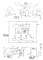
- FIG. 5 schematically illustrates an example of such a system comprising three transmitting terminals, BE 1 to BE 3 , covering the respective zones Z 1 to Z 3 .
- a tourist U x when disembarking, a tourist U x , equipped with a receiver R x calibrated on the frequency transmitted by the terminal BE 1 , enters a first zone Z 1 (coverage zone of BE 1 ) and collects information guiding it towards sites to visit or shops. When it leaves this zone Z 1 , it enters a second zone, for example zone Z 2 , zone of coverage of the transmitting terminal BE 2 , or zone Z 3 , zone of coverage of the transmitter terminal BE 3 . It then collects new information, specific to these areas (particular monuments, tourist sites, etc.).
- the transmission frequency (channel) is common to the different terminals and all the receivers R x are set to this single frequency. It is then necessary that the transmission power is calculated so that there is no overlap between zones.
- the transmission frequency (channel) is separate for each terminal. So he is necessary that we can select from multiple channels. This can be achieved by placing using a frequency blocking device, i.e. with a multi-position switch, or the provision of several receivers strictly single frequency.
- the information disseminated by the transmitting terminals can be permanent or semi-permanent. It is enough then to provide them with an appropriate reader: reader compact disc, loop tape drive, memory digital, etc. We can also plan a program which depends on various time stamped parameters: day of week, time of day, etc. We can finally install a system allowing "refresh" in real time information disseminated. This provision is notably advantageous for all information of a character ephemeral: weather information, personal calls, etc. To do this, you can connect the transmitting terminals to a central station (for example at the tourist office or to any other authorized authority) by a land link (coaxial cable, telephone link, etc.) or a link radio. In the latter case, it is necessary to provide the transmitting terminals of a receiver operating on a frequency different from the frequency (s) of emission terminals.
- the electrical energy necessary for the operation of the transmitting terminals, BE 1 to BE 3 can be supplied by the sector or by rechargeable batteries, for example by solar panels or wind turbines.
- transceiver system interests holiday clubs or similar (club hotel, etc.). This application resumes largely the layouts of the two apps which have just been described.
- FIG. 6 illustrates an example of architecture of such a system.
- a single BE terminal placed in the club's enclosure 5, is generally sufficient to cover the entire site so as to disseminate information received by club members.
- Each is provided with a receiver, R 1 to R 6 , in accordance with the invention, calibrated on the transmission frequency.
- the club can, via the BE transmitting terminal, broadcast information concerning club activities or any other message, or background music or relay general information.
- the BE transmitting terminal can be either fixed or be made up of a portable transmitter as suggested Figure 6. Although in this Figure 6, there is shown a BE transmitter with only a Mic microphone and a audio cassette player it is clear that one can complete the installation with other sound sources.
- the BE terminal could in particular consist of a console similar to the console 3 of FIG. 3, associated with one or several portable transmitters.
- the portable transmitter (s) can be used during excursions or visits guided off site.
- Similar architecture can be used to the guided tour of a museum, with a single series of monofrequency receivers entrusted to visitors, or more series, the receivers of each series being set on a specific frequency, for example to broadcast comments in different languages. So he is need to use multiple transmitters.
- the invention can be applied to bicycle tourism.
- Each participant is equipped, so similar to what has been described with regard to FIG. 4, of a receiver according to the invention.
- the guide can be one of the participants in the hike, or if the transmitter is far enough stay away. We can still provide, as in the case of the "cruise ship” application, described with reference to FIG. 5, transmitting terminals placed along the course.
- the receivers we will adopt advantageously, for the case, the format of a card credit, as defined by ISO standards for length and width.
- the thickness will be of the order of 10 to 15 mm.
- Use of one or two LR03 batteries, i.e. 1.5 V or 3 V nominal, will allow multiple autonomy 6 hours (12, 18 or 24 hours) with integrated circuits commonly available.
- Reception frequency blocked can be preset at the factory.
- some models can allow the selection of a channel from a limited number of predefined channels (by example three channels), if the receiver has a multi-position switch accessible from the outside.
- the frequency naturally depends on the precise application and standards in force in the country concerned. As example, it can be chosen from the range of above frequencies covering the band 183.5 to 186.5 MHz or still in the band 175.5 to 178.5 MHz.
- the attachment system of the housing can take advantageously two main forms.
- the housing 50 of the receiver is provided a clip 51 which allows it to be hung on the belt or lapel of a garment.
- the housing 50 includes a system 54 pendant type attachment, allowing it to be worn around the neck in medallion.
- test 52 accessible from the outside avoiding opening the housing.
- the housing 50 finally has an outlet audio frequency, for example of the female jack 53 type.
- the Ec headset or earphone is fitted with a male 60 jack whose insertion into the audio frequency output 53 results advantageously the commissioning of the receiver R.
- the connecting wires with the transducer (s) electroacoustic (s) 63 also serve as receiving antenna electromagnetic signals to be picked up.
- the setting volume will preferably be achieved by a variable resistance wheel 61, placed on the wire link 62 or directly on the Ec helmet.
- the number of well receivers which a priori is not limited, will typically be of the order of thirty to fifty, which covers, for example, the needs of a "coach operator" application.
- the technical characteristics of the transmitters vary depending on whether it is a fixed terminal or a transmitter portable, especially with regard to the power emitted.
- the transmission power can vary between a minimum of 10 mW to a maximum of 100 mW to 2W, according to the standards in force.
- the energy supply source electric will be, for example, a rechargeable battery 12 V for a mobile transmitter and an external source, such as the mains, 125 to 245 V, 50 or 60 Hz, depending on the country. You can also use solar panels or a wind power source recharging a accumulator.
- the transmitting antenna consists of a single strand in the case of a mobile transmitter and an external antenna powered by a coaxial cable.
- the receiver could constitute an advertising object for stations broadcasting on the FM band or from advertisers using advertising times on these stations. The case is then provided with a logo or distinctive signs recalling the name of the station or advertiser. Knowing that from one region to another the allocated transmission frequency is different, the distributed receiver is a receiver single frequency, factory preset on the appropriate channel for the region or set using a switch multiposition.
Landscapes
- Engineering & Computer Science (AREA)
- Signal Processing (AREA)
- Computer Networks & Wireless Communication (AREA)
- Mobile Radio Communication Systems (AREA)
- Transceivers (AREA)
Applications Claiming Priority (2)
| Application Number | Priority Date | Filing Date | Title |
|---|---|---|---|
| FR9707431A FR2764756B1 (fr) | 1997-06-16 | 1997-06-16 | Systeme d'emission-reception a dispositif de blocage de frequence, notamment pour la radiodiffusion touristique |
| FR9707431 | 1997-06-16 |
Publications (1)
| Publication Number | Publication Date |
|---|---|
| EP0886383A1 true EP0886383A1 (de) | 1998-12-23 |
Family
ID=9508015
Family Applications (1)
| Application Number | Title | Priority Date | Filing Date |
|---|---|---|---|
| EP98401441A Withdrawn EP0886383A1 (de) | 1997-06-16 | 1998-06-12 | Rundfunksystem für Touristenort |
Country Status (2)
| Country | Link |
|---|---|
| EP (1) | EP0886383A1 (de) |
| FR (1) | FR2764756B1 (de) |
Cited By (5)
| Publication number | Priority date | Publication date | Assignee | Title |
|---|---|---|---|---|
| GB2351402A (en) * | 1999-06-01 | 2000-12-27 | James Alexander Spicer | Fixed frequency radio receiver |
| WO2003055079A3 (en) * | 2001-12-21 | 2003-09-25 | Peter Richard Stansby | Method and means for short range multi-channel communication to a number of mobile receivers |
| US7240108B2 (en) | 2001-08-30 | 2007-07-03 | International Business Machines Corporation | Customized tours using handheld devices |
| GB2533202A (en) * | 2014-11-14 | 2016-06-15 | Via Tech Inc | Multimedia playing system |
| CN106357359A (zh) * | 2016-08-18 | 2017-01-25 | 广州市迪士普音响科技有限公司 | 一种智慧公共广播控制方法及系统 |
Citations (5)
| Publication number | Priority date | Publication date | Assignee | Title |
|---|---|---|---|---|
| US2883523A (en) * | 1955-09-07 | 1959-04-21 | Francis P Meserow | Wireless communication system |
| US3934202A (en) * | 1974-03-25 | 1976-01-20 | Telesonic Systems, Inc. | Tour guide system including means for noise and crosstalk suppression |
| WO1991006158A1 (en) * | 1989-10-18 | 1991-05-02 | Neil Poch | Recorded message delivery system |
| FR2700900A1 (fr) * | 1993-01-28 | 1994-07-29 | Belon Camping | Système de diffusion localisée de messages. |
| FR2734432A1 (fr) * | 1995-05-16 | 1996-11-22 | Barneau William | Systeme de bornes d'emission automatique et recepteurs monofrequences |
Family Cites Families (1)
| Publication number | Priority date | Publication date | Assignee | Title |
|---|---|---|---|---|
| US3988701A (en) * | 1975-12-08 | 1976-10-26 | Gte Sylvania Incorporated | Oscillator frequency switching circuit for remote control transmitter |
-
1997
- 1997-06-16 FR FR9707431A patent/FR2764756B1/fr not_active Expired - Lifetime
-
1998
- 1998-06-12 EP EP98401441A patent/EP0886383A1/de not_active Withdrawn
Patent Citations (5)
| Publication number | Priority date | Publication date | Assignee | Title |
|---|---|---|---|---|
| US2883523A (en) * | 1955-09-07 | 1959-04-21 | Francis P Meserow | Wireless communication system |
| US3934202A (en) * | 1974-03-25 | 1976-01-20 | Telesonic Systems, Inc. | Tour guide system including means for noise and crosstalk suppression |
| WO1991006158A1 (en) * | 1989-10-18 | 1991-05-02 | Neil Poch | Recorded message delivery system |
| FR2700900A1 (fr) * | 1993-01-28 | 1994-07-29 | Belon Camping | Système de diffusion localisée de messages. |
| FR2734432A1 (fr) * | 1995-05-16 | 1996-11-22 | Barneau William | Systeme de bornes d'emission automatique et recepteurs monofrequences |
Cited By (6)
| Publication number | Priority date | Publication date | Assignee | Title |
|---|---|---|---|---|
| GB2351402A (en) * | 1999-06-01 | 2000-12-27 | James Alexander Spicer | Fixed frequency radio receiver |
| GB2351402B (en) * | 1999-06-01 | 2003-11-05 | James Alexander Spicer | Radio reciever |
| US7240108B2 (en) | 2001-08-30 | 2007-07-03 | International Business Machines Corporation | Customized tours using handheld devices |
| WO2003055079A3 (en) * | 2001-12-21 | 2003-09-25 | Peter Richard Stansby | Method and means for short range multi-channel communication to a number of mobile receivers |
| GB2533202A (en) * | 2014-11-14 | 2016-06-15 | Via Tech Inc | Multimedia playing system |
| CN106357359A (zh) * | 2016-08-18 | 2017-01-25 | 广州市迪士普音响科技有限公司 | 一种智慧公共广播控制方法及系统 |
Also Published As
| Publication number | Publication date |
|---|---|
| FR2764756B1 (fr) | 1999-09-24 |
| FR2764756A1 (fr) | 1998-12-18 |
Similar Documents
| Publication | Publication Date | Title |
|---|---|---|
| ES2277419T3 (es) | Un metodo para producir simultaneamente ficheros de audio en dos telefonos. | |
| EP1041737B1 (de) | Knoten und Station an Bord eines Fahrzeuges zur Verbindungsaufnahme mit einem Fahrzeuginsassen | |
| MXPA03012027A (es) | Servicios de transmision multimedia para telefonos celulares y otro usuarios y tarjeta de modulo de identificacion del suscriptor modificada para permitir una recepcion de transmision. | |
| EP1442567B1 (de) | Drahtloses mehrzweckkommunikationssystem | |
| EP0886383A1 (de) | Rundfunksystem für Touristenort | |
| EP0580457A1 (de) | Verfahren und Einrichtung zur Übertragung von Information und breitbandigen analogen und/oder digitalen Signalen durch Benutzung der elektrischen Energieversorgungsnetzes | |
| EP3900219B1 (de) | Verfahren um eine mobilfunkverbinbung in einem geschlossenen raum durch eine externe fernsehantenne bereitzustellen und entsprechende vorrichtung | |
| EP1605603A1 (de) | Lokales audiovisuelles Verteilungssystem mit PLC | |
| EP1090380B1 (de) | Informationssystem für passagiere eines verkehrsmittels | |
| EP2235942A1 (de) | System, tragbares objekt und endgerät zur entschlüsselung verschlüsselter audio- und/oder videodaten | |
| EP0701751B1 (de) | Autoradio mit eingebautem sendeempfänger | |
| FR3010597A1 (fr) | Dispositif de communication sonore sans fil bidirectionnelle | |
| EP1457091A2 (de) | Verfahren und system zur selektiven rundfunkübertragung von informationen in einem raum und in diesem system betriebene einrichtungen | |
| US7590385B2 (en) | System for sharing human perceptual signals between electronic devices | |
| WO2015036691A1 (fr) | Dispositif de communication sonore sans fil dans un milieu dense en frequences | |
| WO2022167618A1 (fr) | Boîtier et procédé de demande d'arrêt pour bus | |
| EP1216566B1 (de) | Vorrichtung zur kombination von umgebungs- und kommunikationssignalen | |
| EP1117234A1 (de) | Netz von Kommunikationsmodulen und Module für einfache, für mobile und für fixe Kommunikation | |
| FR2689352A1 (fr) | Système de transmission de messages constitués notamment de signaux vocaux et élément portable de transmission de ces messages. | |
| WO1988001821A1 (fr) | Configuration telephonique du type mains libres pour teleconferences | |
| EP1266457A1 (de) | System zur funkübertragung kurzer reichweite mittels elektronischer tragbarer geräte | |
| FR2970389A1 (fr) | Kit pour equipement de bord de vehicule | |
| WO2004100060A2 (fr) | Systeme de reception radiofrequence et objet portable associe | |
| FR3010596A1 (fr) | Dispositif de communication sonore sans fil dans un milieu dense en frequences | |
| CA2373174A1 (fr) | Systeme de transaction electronique par dispositif personnel portatif |
Legal Events
| Date | Code | Title | Description |
|---|---|---|---|
| PUAI | Public reference made under article 153(3) epc to a published international application that has entered the european phase |
Free format text: ORIGINAL CODE: 0009012 |
|
| AK | Designated contracting states |
Kind code of ref document: A1 Designated state(s): AT BE CH DE ES FR GB GR IT LI PT SE |
|
| AX | Request for extension of the european patent |
Free format text: AL;LT;LV;MK;RO;SI |
|
| 17P | Request for examination filed |
Effective date: 19990621 |
|
| AKX | Designation fees paid |
Free format text: AT BE CH DE ES FR GB GR IT LI PT SE |
|
| R17P | Request for examination filed (corrected) |
Effective date: 19990618 |
|
| STAA | Information on the status of an ep patent application or granted ep patent |
Free format text: STATUS: THE APPLICATION IS DEEMED TO BE WITHDRAWN |
|
| 18D | Application deemed to be withdrawn |
Effective date: 20020103 |