EP0886541B1 - Spielbausatz mit verbundsteinen - Google Patents
Spielbausatz mit verbundsteinen Download PDFInfo
- Publication number
- EP0886541B1 EP0886541B1 EP97914008A EP97914008A EP0886541B1 EP 0886541 B1 EP0886541 B1 EP 0886541B1 EP 97914008 A EP97914008 A EP 97914008A EP 97914008 A EP97914008 A EP 97914008A EP 0886541 B1 EP0886541 B1 EP 0886541B1
- Authority
- EP
- European Patent Office
- Prior art keywords
- dovetail
- pieces
- toy construction
- construction kit
- block
- Prior art date
- Legal status (The legal status is an assumption and is not a legal conclusion. Google has not performed a legal analysis and makes no representation as to the accuracy of the status listed.)
- Expired - Lifetime
Links
- 238000010276 construction Methods 0.000 title claims description 36
- 229920003023 plastic Polymers 0.000 claims description 13
- 239000004033 plastic Substances 0.000 claims description 12
- 230000001154 acute effect Effects 0.000 claims description 3
- 230000013011 mating Effects 0.000 claims 1
- 238000009432 framing Methods 0.000 abstract description 36
- 210000002105 tongue Anatomy 0.000 description 13
- 230000009977 dual effect Effects 0.000 description 9
- 230000000712 assembly Effects 0.000 description 4
- 238000000429 assembly Methods 0.000 description 4
- 230000001965 increasing effect Effects 0.000 description 4
- 239000011159 matrix material Substances 0.000 description 4
- 238000000034 method Methods 0.000 description 4
- 239000007787 solid Substances 0.000 description 4
- 238000003491 array Methods 0.000 description 2
- 230000008878 coupling Effects 0.000 description 2
- 238000010168 coupling process Methods 0.000 description 2
- 238000005859 coupling reaction Methods 0.000 description 2
- 238000007747 plating Methods 0.000 description 2
- XLYOFNOQVPJJNP-UHFFFAOYSA-N water Substances O XLYOFNOQVPJJNP-UHFFFAOYSA-N 0.000 description 2
- 239000002023 wood Substances 0.000 description 2
- HIZCTWCPHWUPFU-UHFFFAOYSA-N Glycerol tribenzoate Chemical compound C=1C=CC=CC=1C(=O)OCC(OC(=O)C=1C=CC=CC=1)COC(=O)C1=CC=CC=C1 HIZCTWCPHWUPFU-UHFFFAOYSA-N 0.000 description 1
- 239000000853 adhesive Substances 0.000 description 1
- 230000001070 adhesive effect Effects 0.000 description 1
- 238000004458 analytical method Methods 0.000 description 1
- 230000015572 biosynthetic process Effects 0.000 description 1
- 239000011449 brick Substances 0.000 description 1
- 230000000295 complement effect Effects 0.000 description 1
- 230000003247 decreasing effect Effects 0.000 description 1
- 230000001939 inductive effect Effects 0.000 description 1
- 238000004519 manufacturing process Methods 0.000 description 1
- 238000005259 measurement Methods 0.000 description 1
- 239000002991 molded plastic Substances 0.000 description 1
- 230000003014 reinforcing effect Effects 0.000 description 1
- 238000002791 soaking Methods 0.000 description 1
- 230000000153 supplemental effect Effects 0.000 description 1
Images


Classifications
-
- A—HUMAN NECESSITIES
- A63—SPORTS; GAMES; AMUSEMENTS
- A63H—TOYS, e.g. TOPS, DOLLS, HOOPS OR BUILDING BLOCKS
- A63H33/00—Other toys
- A63H33/04—Building blocks, strips, or similar building parts
- A63H33/10—Building blocks, strips, or similar building parts to be assembled by means of additional non-adhesive elements
- A63H33/105—Building blocks, strips, or similar building parts to be assembled by means of additional non-adhesive elements with grooves, e.g. dovetails
-
- A—HUMAN NECESSITIES
- A63—SPORTS; GAMES; AMUSEMENTS
- A63H—TOYS, e.g. TOPS, DOLLS, HOOPS OR BUILDING BLOCKS
- A63H33/00—Other toys
- A63H33/04—Building blocks, strips, or similar building parts
- A63H33/06—Building blocks, strips, or similar building parts to be assembled without the use of additional elements
- A63H33/08—Building blocks, strips, or similar building parts to be assembled without the use of additional elements provided with complementary holes, grooves, or protuberances, e.g. dovetails
- A63H33/082—Building blocks, strips, or similar building parts to be assembled without the use of additional elements provided with complementary holes, grooves, or protuberances, e.g. dovetails with dovetails
-
- A—HUMAN NECESSITIES
- A63—SPORTS; GAMES; AMUSEMENTS
- A63H—TOYS, e.g. TOPS, DOLLS, HOOPS OR BUILDING BLOCKS
- A63H33/00—Other toys
- A63H33/04—Building blocks, strips, or similar building parts
- A63H33/10—Building blocks, strips, or similar building parts to be assembled by means of additional non-adhesive elements
- A63H33/12—Perforated strips or the like assembled by rods, bolts, or the like
-
- Y—GENERAL TAGGING OF NEW TECHNOLOGICAL DEVELOPMENTS; GENERAL TAGGING OF CROSS-SECTIONAL TECHNOLOGIES SPANNING OVER SEVERAL SECTIONS OF THE IPC; TECHNICAL SUBJECTS COVERED BY FORMER USPC CROSS-REFERENCE ART COLLECTIONS [XRACs] AND DIGESTS
- Y10—TECHNICAL SUBJECTS COVERED BY FORMER USPC
- Y10S—TECHNICAL SUBJECTS COVERED BY FORMER USPC CROSS-REFERENCE ART COLLECTIONS [XRACs] AND DIGESTS
- Y10S52/00—Static structures, e.g. buildings
- Y10S52/10—Polyhedron
Definitions
- This invention relates to toy building blocks and in particular to interconnecting blocks which provide multiple connection means particularly suitable for constructing polyhedron or other geometric shapes.
- the blocks may be used in conjunction with tubular or framing connectors with an I-shaped cross section, or other connectors, including tongues projecting from other blocks and specially configured connectors.
- Such connectors may be advantageously used in conjunction with craft sticks, 1,9 cm by 1,5 mm by 15,25 cm.
- Toy building blocks of many different configurations are of course well known and popular and have always been one of the most popular toys in a wide variety of cultures.
- the building blocks take many different forms and some of these forms have become extremely well known in associate with their respective trademarks.
- the blocks employ various interconnection means to permit them to be snapped together in a fixed relationship in order to build structures.
- Building toys also exist which employ hinged connections between the parts and a number of building toys employ connector pieces which permit structures to be assembled from larger framing pieces. Many prior art building toys have many obvious attractions and should not be cristicised.
- a second patent is U.S. Patent No. 3,811,219, patented May 21, 1974. That patent discloses at least two elongated structural elements of, e.g., T-shape or U-shape.
- the structural elements have spaced opposite ends, each of which has a flange extending transversely to the elongation of the respective element.
- Connecting means is provided at least on the axially outer sides of the respective flanges.
- a third such patent is U.S. Patent No. 4,035,977, patented July 19, 1977. That patent discloses a structural element which include a body having four sides and a pair of oppositely directed lateral end faces. The body is provided with special connecting means which enables a pair of structural elements to be connected with one another.
- a fourth patent is U.S. Patent No. 4,109,409, patented August 29, 1978. That patent discloses a structural element for a multi-element toy kit, which includes an elongated circumferential wall which bounds an interior space which has opposite ends. Special means is provided for complementarity joining similar elements together.
- a fifth patent is U.S. Patent No. 4,171,591, patented October 23, 1979. That patent is directed to an assembly kit which includes hollow structural elements. Connecting elements are provided to connect two structural elements with one another.
- a sixth patent is U.S. Patent No. 4,895,544, patented January 23, 1990. That patent is directed to a toy construction kit which has an angled profiled number with two arms arranged at an angle relative to one another and each which is provided with a plurality of apertures for engagement with locking pegs of joining elements.
- An adaptor includes connecting elements for connecting further components thereto. Elements are also provided for affixing the adapter to the angled profile member.
- a seventh patent is U.S. Patent No. 4,932,916, patented January 12, 1990. That patent is directed to a toy building component having a connecting lug projecting from an end face and which is insertable into a matching opening of an adjacent toy building component for joining the two components together.
- a first such patent is U.S. Patent No. 5,137,486 patented August 11, 1992. That patent provides a connecting element for a construction toy. An assembly of two such connector elements provides for connections in each of two planes which are oriented at right angles to each other.
- a second such patent is U.S. Patent No. 5,199,919, patented April 6, 1993. That patent describes a construction toy system which includes a variety of molded plastic connecting elements which are arranged to be joined with wad-like struts to form complex structural units.
- the connecting elements have angularly related struts receiving recesses each being arranged for lateral snap-in reception of a flange strut.
- a third such patent is U.S. Patent No. 5,350,331, patented September 27, 1994. That patent discloses a construction toy which includes a connector having one gripping sockets and rod-like structural elements having end portions which are specific especially configured to be received in the gripping sockets.
- interconnecting building blocks that can be manufactured in thin-wall plastic, having a basically simple geometric shape interlocking in different directions and capable of a choice of framing pieces.
- additional pieces of other shapes and forms with interconnecting means suitable for assembly will be provided. These will construct many geometrical shapes such as polyhedral and circular structures which will be highly educational and very entertaining.
- the present arrangement begins from a cubical self-joining feature (which can be referred to as the primary blocks ) which can be interconnected to form a larger three-dimensional planer surface.
- the blocks are not only self-interlocking but also have an extra capacity to use framing pieces and interconnecting pieces which are supplied with either a tubular or I-shaped cross-section or other interconnecting elements (such as plate-sections with appropriate tongues and compatible supports) inducing craft sticks, 1,9 cm by 1,5 mm by 15,25 cm and also 1,27 cm rounded wood-doweling.
- the invention includes a number of the primary blocks and other specifically designed pieces and connectors with interlocking capability. These pieces, with connectors, are provided in kit form.
- the primary blocks preferably have one or more faces designed with apertures to receive a connector or elongated framing projection with rounded ends or I-shaped cross section.
- a connector or elongated framing projection with rounded ends or I-shaped cross section.
- craft sticks being 1,9 cm" by 1,5 mm" by 15,25 cm
- Other faces also incorporate means of joining blocks to each other to form larger building configurations.
- interconnectors may include a pin projecting from one part, particularly sized to engage a sleeve incorporated in another part, for hinged union so that blocks may rotate with respect to each other.
- This pin and sleeve combination is slightly tapered so that a snug fit is achieved at full engagement, (referred to as male hinge and female hinge piece).
- the interconnectors could also alternatively include a male dovetail tongue on one part, particutarly sized to engage a female groove elsewhere The said connection will enable one block to successfully engage with another.
- the block is triangularly-shaped and has the unique advantage of interlocking with similar ones to form a circular array
- a hexagon with a circular aperture, derived from this construction, is sized to engage the other rounded framing pieces of the kit. This offers an interlocking means for other pieces to radiate at various angles, (referred to as triangle block ).
- dovetail connections arranged on the sides of the block, provide an alternate advantage allowing them to be interconnected in overlapping fashion, forming a matrix that structures the base for a self-expanding array.
- a wedge-shaped block (referred to as wedge block ) is included that can interconnect two primary blocks at a regular angle and a circular array may be formed when the pattern is continued.
- Some blocks (referred to as vertex block ) may be added to the kit suitably designed to interconnect additional circular arrays offset around a common centre to form vertices. This can form the greater circles of a sphere.
- the primary block having interlocking faces circumferentially arrayed on four sides
- tapered hub specifically shaped interconnecting pieces
- offset-wedge blocks both the last mentioned blocks when used with other building pieces can be particularly useful for building configurations such as regular and semi-regular polyhedra
- the word “block” will be used generally for convenience, although the word “piece” will be used interchangeably.
- the word “piece” is perhaps more accurate, since not all of the pieces are shaped like a “block.”
- Use of the word “block” is not intended to limit the invention to pieces which are shaped like a "block.”
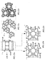
- FIG 1 is an illustrative view of a typical semi-regular polyhedron this one being the truncated octahedron constructed in accordance with the preferred embodiment of the present invention.
- the device being constructed by a combination of two different building pieces consisting of the primary block 1 and the tapered hub 36d , It can be seen that the tapered hubs 36d are interlocked with the primary blocks 1 conically around each vertex of the polyhedron. Also the polyhedron can be increased in size by adding more of the blocks uniformly to each face without changing the overall shape.
- the invention does not restrict the use of these blocks.
- a customised piece, designed with two end connection means could replace a string of primary blocks.
- FIG. 2a shows the top view of the same hub 36d and FIG. 2b shows its side view
- E.A. edge angle
- FIG. 2a shows the E.A. displayed between the male dovetails 9 and it shows a typical configuration of 131° 49' between the two hexagon sections and the section making up the square being 96° 23 ' these angles are configured around a vertex line to the centre of the polyhedron.
- FIG. 2b also shows an angle W.A. ( wedge angle ) these two angles will be described in detail with FIG. 19 further on.
- FIG 3a is a perspective view of two primary blocks 1 interlocked together, the blocks each having one male dovetail 9 and three female dovetail faces 10 , each female dovetail being chamfered at the openings 10a to ease location for a slide fit.
- the blocks have the unique feature of being able to form a new dovetail 9 from two correctly configured (see FIG. 12b) portions 9a, 9b, of the two blocks
- FIG 3b is a cross-sectional view of the block 1 and shows in more detail the shape of the aperture that passes through the two end faces.
- the circular opening 2 is split into four slots 20 and form a T-shape 25, thus providing the block with the ability to receive a narrow rectangular or I-shaped connector piece, in any of four orientations at a 90-degree angle to each other
- the same block can also receive a circular connector piece in the opening 2 , to give the block the unique advantage of receiving the choice of three different shaped connector pieces.
- the male dovetail 9 of the said blocks is shown with a split, 15 . The purpose of the split is to provide a little flexibility in the male portion, for a smoother fit into the female portion
- FIG 3c shows the outline of the primary block 1 which is shown in FIG. 3b.
- the four portions 5 make up the preferable area for a customised ejector tube slotted at 20, to push against the plastic block enabling ejection from its mould-base.
- FIG 4 is a perspective view of a circular connector piece.
- Circular portion 3 is sized to fit the cavity 2 in the Block 1 .
- a circular plate 4 is provided to be accommodated within the recessed area 17 of the primary block, so that blocks can abut each other directly, rather than be separated by the thickness of the plate portion 4 .
- a rib 4a is also shown, this is to locate the slot 20 of the blocks, thus preventing the blocks from rotating to each other when interconnected.
- FIG . 5a is a perspective view of the triangle block 24 , which has two faces with female dovetail grooves 10 , the ends of the grooves being chamfered 10a to ease assembly, the third face being a male dovetail tongue 9 .
- Each corner of the said block is arched 7 to provide a circular aperture when six blocks are interconnected to form a hexagon piece, (see FIG. 12a).
- FIG 5b shows a cross-sectional view of the triangle block 24 as shown in FIG. 5a.
- FIG. 6 is a perspective view showing a craft stick 8 and FIG. 7 shows another elongated connector piece 14 which is I-shaped in cross-section.
- the reinforcing side walls 18 are used to strengthen the framing piece if manufactured in thin-wall plastic
- a plate portion 21 spans between the side walls, and is intended to abut the block
- FIG . 8a and FIG. 8b are male and female hinge pieces, one having a pin and the other having a corresponding sleeve.
- a male pin 12 is offset from one block, and is adapted to mate with a female sleeve 13 incorporated into the other block The pin and sleeve are slightly tapered such that a snug fit is achieved at full engagement between said pin and said sleeve.
- Female dovetail 10 and male dovetail 9 are also provided, although other forms of connection could be used if preferred.
- a portion 13a is provided to act as a stop to limit the hinge swing and to align the hinges when closed. The stop 13a can be eliminated if preferred and pin 12 and sleeve 13 may be positioned to give a swing equally in both directions.
- FIG. 9 is a perspective view of a dovetail 9 to tongue 19 connector and showing a split 27 .
- FIG. 10 shows another primary block 1 and
- FIG . 11 shows a short connector piece 16 which is I-shaped in cross-section. It is essentially a short version of the elongated connector piece 14 shown in FIG. 7.
- the tongue 19 is split at a slot 27 .
- two connector pieces may be inserted in opposite ends of the same block, at a 90-degree angle to each other.
- FIG 12a is a cross-sectional view of a circular arrangement of triangle blocks 24 and FIG. 12b is an arrangement of primary blocks 1 , to demonstrate that the measurements of both groups of blocks have similar outer dimensions. Also note that the three primary blocks 1 are interlocked to form a matrix.
- FIG . 13a - 13c shows how the dimensions of the primary blocks 1 are configured to form a new dovetail 9 from two correctly configured (see FIG.3a) portions 9a , 9b , of the two blocks
- FIG . 13a shows a side view of primary block 1 and dimension C is the mid-height or mid-depth distance across the female dovetail groove
- the said female dovetail is chamfered at both openings 10a and the mid-height or mid-depth distances at the outside edges are defined as C + 2f in which f is the distance of the chamfer at 10a
- FIG. 130 -13c shows how the dimensions of the block are defined as follows
- a nominal square of the side dimension D is defined by nominal lines drawn parallel to the side faces through mid-height or mid-depth points of the dovetail tongues or dovetail grooves as the case may be
- the further dimensions of the block, as illustrated in FIG. 13c, are in accordance with the formulae.
- A is the distance from one edge of dovetail tongue or dovetail groove at the mid-height or mid-depth thereof to its adjacent edge of the said nominal square
- B is the distance from the opposite edge of the dovetail tongue or dovetail groove at the mid-height or mid-depth thereof to the adjacent edge of the said nominal square
- C is the width of the dovetail tongue or dovetail groove at mid-height or mid-depth thereof.
- Each dovetail tongue or dovetail groove is centred on the face of the nominal square, D being the length of each side of the square.
- FIG. 13b illustrates how increasing the distance C by an amount f , drastically alters the configuration and the amount which are added onto a female dovetail groove is reduced on the male dovetail portions, making a loose fit.
- FIG 14a is a perspective view showing a configuration of primary blocks 1 and wedge blocks 22 .
- the wedge block 22 also shown in FIG 14b is provided with two male dovetails 9 on two opposite faces, decreasing in an acute angle.
- the wall thickness of the block is designed to use thin-wall plastic and may be ejected out of a mould by pushing around the circular portion (other bracing shapes could also be used ) of the block 5a .
- the block 1a acts as the vertex block similar to the primary block 1 but contains all female connection means 10 as shown in the cross-sectional view FIG. 14c or 14d. These end views of 1a are ideal shapes for extruding longer pieces of the same profile. It is easy to form the greater circles of a sphere by using the vertex blocks and assembling two or more circular arrays of blocks.
- the vertex block could be provided with three or numerous female connection faces other than the four shown in FIG. 14c.
- FIG. 15a illustrates a male to male dovetail connector piece 31 , referred to as male to male connector .
- FIG. 15b shows an arrangement of four primary blocks 1 that can be connected in a combination of 60-degree and 120-degree angles by using two triangle blocks 24 and a male to male connector 31
- FIG. 15c shows more variations using a combination of primary blocks 1 and triangle blocks 24 There can be numerous variations of structures to be achieved with the said blocks.
- FIG. 16 illustrates an arrangement of primary blocks 1 with elongated circular framing connector pieces 28 .
- An optional shoulder 29 is provided and ends 3 are sized to fit the aperture 2 of the primary blocks 1 .
- the framing pieces 28 may be manufactured from tubular plastic, or from solid wood doweling.
- FIG. 17a and FIG. 17b being the end view, illustrates an alternate elongated framing piece with similar end connections 3 and provided with the shoulder 29a which uses a square section 28a that can be made from wood.
- the square section 28a is customised with slots 30 which can be used to support a thin rectangular plate if desired.
- the previously mentioned elongated framing pieces may have other configurations to support boards or plating sections at other angles if desired.
- FIG 17c shows the end view of a customised connector similar to FIG. 17a - 17b designed for manufacturing in thin-wall plastic
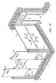
- FIG. 18 is an illustration of a modular structure using interlocking primary blocks 1 and the use of framing pieces 28a to support plate sections 32, 32a, 32b and 32c to form a structure of a miniature toy store.
- the framing pieces 28a are slotted 30 on all four sides to receive the edges of the plating sections.
- the plates may be inserted between two framing. pieces as shown with plate 32 or the plate as shown 32c may be shaped to form a doorway 35 , or if desired, the plate could be customised to provide a window opening.
- the plates may also be supported by additional tongues 8a that may be inserted into the cavities 20 of the primary blocks 1 (see FIG . 3b).
- the plates may be illustrated 34 (door-frame 34a ) by print or decals and may use transparent plastic to make shop windows.
- the boards may also be illustrated by the children with coloured pens.
- FIG. 19 FIG. 20a & 20b, and FIG. 21 which provides more detail for configuring the tapered hub which is instrumental in the construction of polyhedra
- a simple cube and tetrahedron are good examples for using a tapered hub combination
- the three male connecting faces 9 of the tapered hub 36a radiate congruently around the axis from the centre 39 and the vertex 41 of this polyhedron
- These three faces 9 will converge towards the vertex 41 and interconnect primary blocks 1 to be perfectly aligned with the outer edges of 40a, 40b, 40c - 41 of the tetrahedron and in a triangular plane 40a, 41 to the centre 39 .
- the converging angle is referred to as W.A. (wedge angle) and is configured as 1/2(180° - centre angle) which is 1/2 (180° - 109 ° 28' ) being an angle of 35° 16'.
- the centre angle C.A. (defined as theta) is shown at the centre 39 of the tetrahedron 38 subtended by its edge 40a-41 .
- the centre angle of a tetrahedron being 109° 28' is the supplementary angle to that of a cube which is 70° 32'. Therefore by rotating the tapered hub 36a end for end, they may be used for both polyhedra but the blocks are oriented at a 90-degree angle in the latter interconnections as shown in FIG.21. Because of this difference in orientation, it is now possible for the primary blocks 1 to be self-interlocking along the face edges ( 48 to 51 ) of the cube 42 .
- the interesting characteristics of this particular hub may be applicable to other structures such as the cuboctahedron or the octet truss.
- the wedge angle W.A. is now 1/2 the centre angle.
- the face edge 48-51 of the cube 42 can be seen to be subtended by the centre angle C.A. (defined as theta).
- the wedge angle W.A. is the angle at X between the centre axis 52 of primary block 1 and the centre axis 48 of the tapered hub 36a .
- FIG. 20a shows a top view of the tapered hub 36a and three faces with male dovetail connector means 9 radiating equally around the hub centre axis.
- the circle 2 represents an aperture.
- the sides of aperture 2 and the walls of the tapered hub may be manufactured in thin wall plastic.
- edge angle E.A. ( briefly mentioned in FIG. 2a) and is shown at a 120-degree angle suitable for the three-way vertices of the two regular polyhedra involved. These angles can vary in more complex polyhedra as displayed around the tapered hub used in the illustration of FIG. 1 and FIG. 2a
- the configuration of a typical vertex is shown in FIG. 21 where the edge angle E.A.
- the tapered hubs can produce even more complex polyhedra
- Three of the five regular polyhedra use vertices that can be formed by using a three-way tapered hub 36a .
- the octahedron can be constructed with a four-way hub 36b as shown in FIG. 22a and 22b and the fifth regular solid being the dodecahedron uses a five-way hub 36c as shown in FIG.23a-23b
- the tapered hubs used to construct regular polyhedra will each have congruent wedge angles and edge angles. This is not true for the semi-regular polyhedra as previously mentioned.
- the vertex may share the edges of two hexagons and a square for example as shown in FIG. 1 Therefore, the hubs supplied for these polyhedra will have connection means at various edge angles around the hub centre axis, although the wedge angles may be congruent.
- the hubs supplied for these polyhedra will have connection means at various edge angles around the hub centre axis, although the wedge angles may be congruent.
- the Archimedean solids at least six contain vertices that can be constructed with three-way hubs with various edge and wedge angles and the remainder of the polyhedra may use four or five-way hubs. There are more polyhedra that may possibly be constructed by this method also.
- the tapered hub may support the primary blocks at a 90-degree angle difference in orientation using the tetrahedron as an example. This will then enable the tetrahedron to be constructed with elongated framing pieces connected between the blocks.
- this method is suitable for the tetrahedron, the taper angles of the hub are increased greatly when configured for the more complex polyhedra and it is preferable to use an alternative arrangement such as the offset-wedge block , now referred to in FIG. 24, FIG. 25 and FIG. 26.
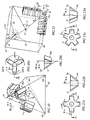
- offset wedge blocks 56c as shown in FIG 24 are interconnected between a circular array of primary blocks 1 , they converge in a conic conjunction around a focal vertex 53a .
- This method of forming a vertex with these offset-wedge blocks is useful if the primary block is to be supported with its apertures in line with the face edge of a geodesic dome or polyhedron, thus being able to utilize the elongated framing pieces
- the offset-wedge block 56(a, b, c) shows two male dovetail faces 9 displaced with respect to independent angles ( T.C.A. and F.A. ) to each other.
- FIG 24, shows T.C.A. (to the centre angle) as the angle formed by the projection of two lines from the points 58,59 (which are midpoints of the face edges being at 90-degrees in relation to the craft sticks 8 ) so constructed to intersect at the centre point 57 of the sphere or polyhedron under construction.
- the second angle which is referred to as F.A. (face angle) is the angle between two face edges ( 54,55 ) at the vertex point 53a .
- FIG. 26 is an illustration of a geodesic dome constructed with radial configurations of five 53b and six-way 53a vertex assemblies similar to FIG. 24 as mentioned.
- the dome structure also uses elongated framing pieces 8 and by increased length the dome can be enlarged without changing the angular integrity or shape.
- the dome is based on the Archimedean semi-regular polyhedron, specifically the icosidodecahedron consisting of 12 pentagons and 20 triangles. Five craft sticks 8 supported by primary blocks 1 unite the five vertices 53a to form the perimeter of the pentagon.
- the said pentagon is subdivided by five triangles consisting of craft sticks 8 supported by two primary blocks 1 interconnected by two offset-wedge blocks 56b at the base and further craft sticks radially supported by primary blocks 1 , interspersed by offset-wedge blocks 56a at the focal vertex 53b
- the neighbouring triangles around the pentagons configuring this respective polyhedron are similarly arranged in like format using a third customised offset-wedge block 56c .
- the combinations of these three wedge blocks are the essentials necessary for the structural configured surface of this geodesic dome
- FIG. 27 is an illustration of a dual polyhedra 60a using the configuration of the dodecahedron which uses a three-way tapered hub 36e having a 120-degree edge angle and a wedge angle of 20°54' which is interconnected with four-way blocks 1a also shown in FIG. 14c.
- This block acts as the fundamental building piece for forming the thirty edges of the dodecahedra and thirty edges of the icosahedron by interconnecting with the five-way vertex configuration (1c, 22a) .
- This five-way vertex is made up of a five-way block similar to the four-way block 1a and this is made into a five-way tapered hub by interconnecting five wedge blocks 22b which has a 31° 43' angle.
- the tapered hub assemblies (36e,22a, 1c ) and the four-way blocks 1a are all provided with apertures 2 This total of sixty-two apertures can support round framing pieces 28 as shown in FIG 16 These framing pieces will radiate outwards in the vector configuration of the dual polyhedra and can be used to support tapered hubs to form even larger dual polyhedra or a single dodecahedra with 20 vertices or icosahedra with 12 vertices
- the geometry books will show that the intersection of edges (being the apertures of the four-way blocks 1a ) will also be aligned to the 30 vertices of the quasi-regular icosidodecahedron.
- FIG. 28 is another illustration of an alternate spherical combination 60b , this one shows the cube and octahedron in a duelling configuration.
- This assembly now uses four-way blocks 1a with four 45-degree wedge blocks 22 to form a tapered hub assembly and it takes six of these assemblies to form the octahedra.
- the duelling cube however uses eight three-way hubs 36a which needs a wedge angle of 35° 16' to interconnect with the octahedra
- the edges of this dual polyhedra again uses a four-way configuration 1a as described in the FIG. 27 for the five-way dual polyhedra.
- the tapered hubs 36a and four-way blocks 1a all contain the apertures 2 .
- FTG.29 is an illustration showing a portion of an assembly of eight cubes to be built into a larger cubical formation. It can be seen that these vertex interconnections of the cubes are made up of blocks 1a and 45-dergree wedge blocks 22 which can form the spherical structure similar to FIG. 28.
- the framing pieces 28b makes up the side edges of the cube. It can be seen that using the framing pieces 28c the hypotenuse of the cube can be formed. This breaks down this configuration into individual tetrahedrons.
- FIG 28 is an illustration of the tapered hub 36a which can be manufactured in thin wall plastic.
- the aperture of this hub is made similar to that of the four-sided block but the aperture 2 is split three-way, this allows for a flexible fit for framing pieces.
- a bridge 61 is also provided to brace the centre area for firmness. Also shown are the top profiles 62a and bottom profiles 62b of the hub 36a . Each of these profiles could also be used as end profiles of parallel faced connecting pieces and extruded to any length. Although the previous examples show polyhedra and a geodesic dome, this does not restrict the invention to these shapes. With the appropriate angular configurations of the conical assemblies and framing features, it is possible to form any three dimensional models with a framed mesh similar to computerized surface modelling. A water soluble adhesive could be used to secure the interconnections uniting the models and then removed again by soaking in water.
Landscapes
- Toys (AREA)
- Peptides Or Proteins (AREA)
Claims (23)
- Spielzeugbausatz umfassend eine Mehrzahl von modularen Komponenten, von welchen jede eine zentrale longitudinale Achse aufweist, zum Bauen von dreidimensionalen Strukturen mit einer Mehrzahl von untereinander verbundenen benachbarten Komponenten, wobei die dreidimensionalen Strukturen reguläre und archimedische Polyeder umfassen und wobei die modularen Komponenten umfassen:(I) mindestens einen prismatischen Block (1, 1a, 1c) mit einer Mehrzahl von Seitenwänden, wobei jede Seite eine festgelegte Länge aufweist, wobei die Seiten eine Mehrzahl von Verzahnungsverbindungselementen (9, 10) definieren, welche sich parallel zu der zentralen longitudinalen Achse erstrecken, wobei die Seiten und Verzahnungselemente erste und zweite Endflächen definieren, wobei ein Umfang zumindest der ersten Endfläche ein Minimum von drei Vertiefungen (2, Fig. 3b, Fig. 14c, Fig. 14d) definiert, welche zu der zweiten Endfläche (Fig. 3a) hin verlaufen, wobei die Vertiefungen durch innere Grenzwände getrennt sind, welche sich parallel zu der zentralen longitudinalen Achse erstrecken, wobei die inneren Grenzwände zumindest ein Teil der festgelegten Länge der Seitenwände sind, und(II) ein zweiter Satz von Elementen, welche aus der Gruppe ausgewählt sind, welche daraus besteht, zumindest eines der folgenden zu umfassen:(i) einen Keilblock (22, 22a, 56(a, b, c), Fig. 14b, Fig. 25) mit einer Basisendoberfläche und einer beabstandeten Endoberfläche, wobei der Block relativ dünne äußere Wände aus Kunststoff mit zwei planaren Seitenoberflächen, welche männliche Verzahnungsverbindungselemente (9) definieren, aufweist, wobei die planaren Seitenoberflächen wechselseitig winkelmäßig um die zentrale longitudinale Achse angeordnet sind und die planaren Seitenoberflächen in einem spitzen Winkel bezüglich der Basisendoberfläche zusammenlaufen, wobei die planaren Seitenoberflächen Achsen definieren, welche sich an einem Scheitelpunkt (53b) schneiden, wobei die beabstandete Endoberfläche zwischen dem Basisende und dem Scheitelpunkt angeordnet ist, wobei der Keilblock weiterhin eine zwischen der Basisendoberfläche und der beabstandeten Endoberfläche vorgesehene Vertiefung umfasst,(ii) einen sich verjüngenden Nabenblock (36a, 36b, 36c, 36d, Fig. 2) mit einer Basisendoberfläche und einer beabstandeten Endoberfläche, wobei der sich verjüngende Nabenblock relativ dünne äußere Wände aus Kunststoff mit mindestens drei planaren Seitenoberflächen, welche männliche Verzahnungsverbindungselemente (9) definieren, aufweist, wobei die planaren Seitenoberflächen wechselseitig winkelmäßig um die zentrale longitudinale Achse angeordnet sind und wobei die planaren Seitenoberflächen in einem spitzen Winkel in Bezug auf die Basisendoberfläche zusammenlaufen, wobei die planaren Seitenoberflächen Achsen definieren, welche sich in einem Spitzenpunkt (41) schneiden, wobei die beabstandete Endoberfläche zwischen dem Basisende und dem Spitzenpunkt angeordnet ist, wobei die sich verjüngende Nabe weiterhin eine zwischen der Basisendoberfläche und der beabstandeten Endoberfläche bereitgestellte Vertiefung umfasst,(iii) ein sechsseitiger Block (1, 1a), welcher aus vier lateralen Seiten, ersten und zweiten Endoberflächen zusammengesetzt ist, wobei jede der lateralen Seiten Verzahnungsverbindungselemente (9, 10), welche parallel zu der zentralen longitudinalen Achse verlaufen und sich zu jeder der ersten und zweiten Endoberflächen hin erstrecken, definiert, wobei die Endoberflächen des Blocks zumindest drei Vertiefungen (Fig. 3b, Fig. 14c, Fig. 14d, 2) definieren, welche von einer der ersten und zweiten Endoberflächen zu der anderen der Endoberflächen verlaufen, wobei die Vertiefungen durch innere Grenzwände getrennt sind und sich parallel zu der zentralen longitudinalen Achse erstrecken, wobei eine der Vertiefungen zylindrisch (2, 5) ist, wobei die Wände der zylindrischen Vertiefung weiterhin zumindest zwei sich radial erstreckende longitudinale Nuten (20, 25) umfassen, wobei die Vertiefung (2, 20, 25) ausgestaltet ist, mit einem axialen Verbindungselement (3, 8, 14, 16, 28, 28a, 28b, 28c, etc.) zusammenzugehören.
- Spielzeugbausatz gemäß Anspruch 1, wobei die Vertiefung des Keilblocks (Fig. 14b) durch eine innere Wand (5a) geteilt ist, welche sich in senkrechter Richtung zwischen der Basisendoberfläche zu der beabstandeten Endoberfläche hin erstreckt.
- Spielzeugbausatz nach Anspruch 1, wobei eine der Vertiefungen (Fig. 3b, 2) des prismatischen Blocks eine im Wesentlichen zylindrische Form mit zumindest zwei sich radial erstreckenden longitudinalen Nuten definiert, jede mit einem radialen inneren Stegabschnitt, welcher um die zentrale longitudinale Achse angeordnet ist, wobei die Vertiefung als axiale Aufnahmevertiefung zur Verbindung mit einem axialen Verbindungselement dient.
- Spielzeugbausatz gemäß Anspruch 1, wobei die Verzahnungsverbindungselemente des prismatischen Blocks weibliche Verzahnungsvertiefungen umfassen und wobei die Vertiefungen abgeschrägte Endflächen (Fig. 3a, 10a) aufweisen.
- Spielzeugbausatz gemäß Anspruch 1, wobei jede der Endflächen des prismatischen Blocks ein vertieftes Wiederlagergebiet (Fig. 3a, 17) radial nach innen von den lateralen Seiten umfasst.
- Spielzeugbausatz gemäß Anspruch 1, wobei die planaren Seitenoberflächen des Keilblocks (Fig. 14b) allgemein männliche Verzahnungselemente (9) definieren, wobei die zwei Seitenoberflächen in einem Winkel von 180° um die zentrale longitudinale Achse angeordnet sind und zu dem Scheitelpunkt hin zusammenlaufen.
- Spielzeugbausatz gemäß Anspruch 1, wobei die planaren Seitenoberflächen des Keilblocks (Fig. 25, 56(a, b, c)) allgemein männliche Verzahnungselemente (9) definieren, wobei die zwei Seitenoberflächen zu dem Scheitel hin zusammenlaufen, wobei die zwei Seitenoberflächen in einem Winkel kleiner als 180° um die zentrale longitudinale Achse angeordnet sind und somit einen Keilblock mit Versatz definieren.
- Spielzeugbausatz nach Anspruch 1 oder 7, wobei eine Nabenstruktur (Fig. 24) durch eine Mehrzahl von Versatz-, Keil- und prismatischen Blöcken mit Verzahnungsverbindungsflächen, welche in ineinander greifender Beziehung angeordnet sind, definiert ist.
- Spielzeugbausatz gemäß Anspruch 1, wobei der sechsseitige Block eine Verzahnungszunge oder eine Verzahnungsvertiefung aufweist, und wobei der Block (Fig. 13c) eine Geometrie in Übereinstimmung mit der Formel:A ein Abstand von einer Kante einer Verzahnungszunge oder Verzahnungsvertiefung in einer mittleren Höhe oder einer mittleren Tiefe zu einer benachbarten Kante eines nominellen Quadrats ist,B ein Abstand von einer gegenüberliegenden Kante der Verzahnungszunge oder Verzahnungsvertiefung in einer mittleren Höhe oder einer mittleren Tiefe zu einer benachbarten Kante eines nominellen Quadrats ist,C eine Breite der Verzahnungszunge oder Verzahnungsvertiefung in einer mittleren Höhe oder einer mittleren Tiefe ist,D ein nominelles Quadrat einer Seite D definiert durch nominelle Linien, welche parallel zu den Seitenflächen durch Punkte mittlerer Höhe oder mittlerer Tiefe gezeichnet sind, ist.
- Spielzeugbausatz gemäß Anspruch 1, wobei die Verzahnungselemente des prismatischen Blocks männliche Verzahnungselemente (9) und weibliche Verzahnungselemente (10) sind.
- Spielzeugbausatz gemäß Anspruch 1, wobei der Bausatz weiterhin Adapterteile mit zwei im Wesentlichen parallelen Flächen umfasst, wobei die Flächen der Adapterteile Verbindungsmittel aufweisen, welche aus der Gruppe ausgewählt sind, welche besteht aus:einem Stift parallel zu einer Seite des Teils (Fig. 8a, 12),einer Hülle parallel zu einer Seite des Teils (Fig. 8b, 13),einer männlichen Verzahnung auf einer Fläche des Teils (Fig. 9, 9),einer weiblichen Verzahnung auf einer Fläche des Teils (Fig. 8b, 10),einer Zunge mit einem rechteckigen Querschnitt, welche aus einer Fläche des Teils (Fig. 9, 19) herausragt,einer Zunge mit einem I-förmigen Querschnitt aus einer Fläche eines der Teile (Fig. 11, (19 und 18)),einer Zunge mit einem kreisförmigen Querschnitt, welche aus einer Fläche des Teils (Fig. 4, 3) herausragt.
- Spielzeugbausatz gemäß Anspruch 11, wobei die Adapterteile Teile mit zwei Verzahnungsoberflächen (Fig. 15, 31) umfassen.
- Spielzeugbausatz gemäß Anspruch 11, wobei die Adapterteile Teile mit einer Verzahnung und einer Zunge auf einer Fläche des Teils (Fig. 9) umfassen.
- Spielzeugbausatz gemäß Anspruch 11, wobei die Adapterteile Teile umfassen, welche zwei Flächen (Fig. 14b) umfassen, wobei jede Fläche ein männliches daran entlang laufendes Verzahnungselement aufweist und wobei die Flächen um ihre gemeinsame Achse angeordnet sind und zu einem Scheitelpunkt hin zusammenlaufen.
- Spielzeugbausatz gemäß Anspruch 11, weiterhin umfassend zumindest zwei Adapterteile zur scharniermäßigen Verbindung zwischen jeglichen der modularen Komponenten, wobei eines der Adapterteile einen daraus herausragenden Stift aufweist und ein anderes der Adapterteile eine Hülle zum In-Eingriff-Gelangen mit dem Stift (Fig. 8a und Fig. 8b) aufweist.
- Spielzeugbausatz gemäß Anspruch 1, weiterhin umfassend langgestreckte Verbindungselemente, wobei die Verbindungselemente mindestens viermal länger als eine äußere Länge der modularen Komponenten sind (Fig. 6, Fig. 7).
- Spielzeugbausatz gemäß Anspruch 1, und weiterhin umfassend Bauteile, wobei jedes der Teile eine Fläche mit einer axial aufnahmefähigen Vertiefung aufweist, und wobei ein Abschnitt der Fläche vertieft ist (Fig. 3a).
- Spielzeugbausatz gemäß Anspruch 1, wobei der Bausatz weiterhin Verbindungselemente mit I-förmigem Querschnitt umfasst, definiert durch einen Hauptsteg und zwei Endarme, und einen Quersteg, welcher sich zwischen den Armen spannt (Fig. 7, Fig. 11).
- Spielzeugbausatz gemäß Anspruch 1, wobei der Bausatz Adapterteile mit mindestens drei Oberflächenflächen umfasst, wobei jede dieser Flächen ein Verzahnungselement umfasst (Fig. 5a, 24).
- Spielzeugbausatz gemäß Anspruch 19, wobei die Adapter eine Größe und Form aufweisen, um mit entsprechenden Verzahnungselementen auf anderen dreieckigen Teilen in Eingriff zu gelangen, um ein sechsseitiges Nabenteil zu bilden (Fig. 12a, 24).
- Spielzeugbausatz gemäß Anspruch 1, wobei die Verzahnungsverbindungsflächen der modularen Komponenten Verzahnungselemente umfassen, wobei zumindest einige der Verzahnungselemente mit Abschrägungen benachbart zu jeder Seitenfläche ausgestattet sind (Fig. 3a, 10a).
- Spielzeugbausatz gemäß Anspruch 3, wobei das axiale Verbindungselement rechteckförmige Felder umfasst (Fig. 18, 32, 32a, 30), welche Kanten aufweisen, welche ausgelegt sind, in aufnahmefähige Vertiefungen eingesetzt zu werden, welche von einer Mehrzahl von miteinander verbundenen Blöcken bereitgestellt werden.
- Spielzeugbausatz gemäß Anspruch 22, wobei die Felder Indizes bzw. Hinweise in Form von gedruckter Materie umfassen (Fig. 18, 34).
Applications Claiming Priority (3)
| Application Number | Priority Date | Filing Date | Title |
|---|---|---|---|
| CA2171355 | 1996-03-08 | ||
| CA002171355A CA2171355A1 (en) | 1996-03-08 | 1996-03-08 | Toy construction kit with interconnecting building pieces |
| PCT/CA1997/000138 WO1997032643A1 (en) | 1996-03-08 | 1997-02-28 | Toy construction kit with interconnecting building pieces |
Publications (2)
| Publication Number | Publication Date |
|---|---|
| EP0886541A1 EP0886541A1 (de) | 1998-12-30 |
| EP0886541B1 true EP0886541B1 (de) | 2004-05-12 |
Family
ID=4157714
Family Applications (1)
| Application Number | Title | Priority Date | Filing Date |
|---|---|---|---|
| EP97914008A Expired - Lifetime EP0886541B1 (de) | 1996-03-08 | 1997-02-28 | Spielbausatz mit verbundsteinen |
Country Status (10)
| Country | Link |
|---|---|
| US (1) | US6059631A (de) |
| EP (1) | EP0886541B1 (de) |
| JP (1) | JP2000513600A (de) |
| AT (1) | ATE266453T1 (de) |
| AU (1) | AU715118B2 (de) |
| BR (1) | BR9707915A (de) |
| CA (2) | CA2171355A1 (de) |
| DE (1) | DE69729075D1 (de) |
| IL (1) | IL126087A (de) |
| WO (1) | WO1997032643A1 (de) |
Families Citing this family (61)
| Publication number | Priority date | Publication date | Assignee | Title |
|---|---|---|---|---|
| ITCN970002A1 (it) * | 1997-01-24 | 1998-07-24 | Giuseppe Frezza | Mappamondo o globo terrestre ad incastri. |
| US6379212B1 (en) * | 1998-03-13 | 2002-04-30 | George R. Miller | System and set of intercleaving dichotomized polyhedral elements and extensions |
| US6921314B2 (en) | 1998-03-13 | 2005-07-26 | George R. Miller | Intercleaving spatially dichotomized polyhedral building blocks and extensions |
| US6578667B2 (en) * | 2000-04-20 | 2003-06-17 | The Boeing Company | Thrust reverser blocker door access platform |
| US6447360B1 (en) * | 2000-04-26 | 2002-09-10 | Soren Christian Sorensen | Interconnection of toy building elements in a releasable restraining engagement |
| US6729984B2 (en) * | 2001-07-28 | 2004-05-04 | Rhino Toys, Inc. | Toy ball apparatus |
| FR2834649B1 (fr) * | 2002-01-11 | 2004-03-19 | Ange Prados | Module articule |
| EP1464369A1 (de) | 2003-04-04 | 2004-10-06 | Theodorus Suibertus Anthonius ROLF | Spielbaustein, dafür geeignete Schraube und Schraubgerät |
| NL1026186C1 (nl) * | 2004-05-13 | 2005-11-21 | Mariana Hertzano | Spelsteen. |
| US7267598B2 (en) * | 2005-06-07 | 2007-09-11 | Connector Set Limited Partnership | Interfacings between block type and rod and connector type construction toy sets |
| US7648407B1 (en) | 2005-07-14 | 2010-01-19 | Soren Christian Sorensen | Toy-building elements having sidewall grooves formed between outwardly extending flexible ridges |
| US7316598B1 (en) | 2005-08-17 | 2008-01-08 | Lock Keith S | Toy construction set |
| NL1031458C2 (nl) * | 2006-03-29 | 2007-10-03 | Rokatec Beheer B V | Klauterinrichting. |
| US7833077B1 (en) * | 2008-04-14 | 2010-11-16 | Simmons Jr Felix J | Pixel blocks |
| US20100109247A1 (en) * | 2008-11-05 | 2010-05-06 | Joseph Cernansky | Interconnecting game tiles and games therewith |
| CA2785319C (en) * | 2009-12-23 | 2018-07-03 | Jonas Hauptman | System and method for structure design |
| TWM390811U (en) * | 2010-03-01 | 2010-10-21 | zhi-hao Zhang | Game frame capable of inspiring geometry concept |
| WO2011126830A2 (en) * | 2010-03-30 | 2011-10-13 | Brickstix Llc | Reusable cling decals for plastic toys, building bricks, and accessories and system for customizing |
| WO2012081994A1 (en) * | 2010-12-13 | 2012-06-21 | Southrim Technology Co. Limited | Interlocking structure with associated modular building assembly system |
| BE1019706A3 (nl) * | 2010-12-16 | 2012-10-02 | Verhaeghe Chalets & Sauna Nv | Wandsamenstel. |
| USD692064S1 (en) * | 2011-05-23 | 2013-10-22 | Dong-Kwon Kim | Blocks for game |
| USD877263S1 (en) * | 2011-10-13 | 2020-03-03 | Building Creative Kids, Llc | Toy coupler |
| US10398998B2 (en) | 2011-10-13 | 2019-09-03 | Building Creative Kids, Llc | Toy couplers including a plurality of block retaining channels |
| US9399177B2 (en) | 2011-10-13 | 2016-07-26 | Building Creative Kids, Llc | Toy couplers including a plurality of block retaining channels |
| USD757860S1 (en) * | 2012-09-12 | 2016-05-31 | Building Creative Kids, Llc | Toy coupler |
| US20130122974A1 (en) * | 2011-11-14 | 2013-05-16 | Nassim Haramein | Modular Frames for Jewelry |
| US9466228B2 (en) | 2011-11-14 | 2016-10-11 | Torus Tech Llc | Modular frames for arrangement and orientation of geometric solids |
| US20130217296A1 (en) * | 2012-02-21 | 2013-08-22 | Addy Soentoro Widjaja | Modular toy system |
| US9498703B2 (en) | 2013-03-13 | 2016-11-22 | Stat Ventures, Inc. | Assembly kit for three dimensional works |
| US9437954B2 (en) * | 2013-04-26 | 2016-09-06 | Interconnect Devices, Inc. | Series connector |
| JP5711864B2 (ja) * | 2013-07-14 | 2015-05-07 | 理 藤井 | 組合せ定規 |
| US10501929B2 (en) | 2013-09-30 | 2019-12-10 | Drew P. HENRY | Hollow connector sleeve with interlocking components |
| DE102013017172B3 (de) * | 2013-10-16 | 2015-01-15 | Stefan Fritz Römmelt | Systembauteil zur Bildung einer Netzstruktur und Aufnahme von Objekten |
| USD798391S1 (en) | 2014-03-26 | 2017-09-26 | T. Dashon Howard | Pentagonal building block |
| US20150321115A1 (en) * | 2014-05-08 | 2015-11-12 | James Fleet Hower | Interlocking Components forming Arbitrary Solids with Complex Curvatures |
| USD802683S1 (en) | 2014-05-27 | 2017-11-14 | T. Dashon Howard | Tetrahedral neutral converter block |
| USD800227S1 (en) | 2014-05-27 | 2017-10-17 | T. Dashon Howard | Tetrahedral negative universal joint block |
| USD798392S1 (en) | 2014-05-27 | 2017-09-26 | T. Dashon Howard | Tetrahedral positive universal joint block |
| USD763970S1 (en) * | 2014-05-29 | 2016-08-16 | T. Dashon Howard | Tetrahedral turbine block |
| USD762268S1 (en) * | 2014-11-08 | 2016-07-26 | Iko, Llc | Interlocking building block |
| US10493371B2 (en) | 2015-01-06 | 2019-12-03 | Building Creative Kids, Llc | Toy building systems including adjustable connector clips, building planks, and panels |
| WO2016131768A1 (en) * | 2015-02-17 | 2016-08-25 | Heasman Murray | An apparatus for playing a game |
| CN106267848A (zh) * | 2015-06-01 | 2017-01-04 | 林美足 | 鸠形积木 |
| USD802058S1 (en) * | 2015-07-15 | 2017-11-07 | Assim Ishaque | Block toy for arts and crafts |
| US20170215345A1 (en) | 2016-01-28 | 2017-08-03 | Oldcastle Building Products Canada Inc. | Connector Block For Assembling a Garden Bed or a Planter Box |
| DK3437082T3 (da) * | 2016-02-02 | 2020-12-07 | Deka Products Lp | Modulært elektromekanisk middel |
| US10029187B2 (en) * | 2016-03-24 | 2018-07-24 | UBTECH Robotics Corp. | Toy assembling apparatus |
| WO2017188390A1 (ja) * | 2016-04-28 | 2017-11-02 | 株式会社壽屋 | 組立式模型玩具とそのパーツ |
| JP7017191B2 (ja) * | 2016-04-28 | 2022-02-08 | 株式会社壽屋 | 組立式模型玩具とそのパーツ |
| TWM542507U (zh) * | 2017-01-12 | 2017-06-01 | Mentari Massen International Co Ltd | 城堡積木 |
| KR200485228Y1 (ko) * | 2017-07-31 | 2018-01-18 | 유니트러스트개발(주) | 연결블록을 구비한 블록 조립 완구 |
| CN111405853B (zh) | 2017-08-01 | 2022-08-19 | 方舟水晶有限公司 | 用于几何实体的模块化框架 |
| US20190160390A1 (en) * | 2017-11-29 | 2019-05-30 | Basic Fun, Inc. | Spacing Connector for Toy Construction Set |
| USD861080S1 (en) * | 2018-03-30 | 2019-09-24 | T. Dashon Howard | Pentagonal tetrahedral block |
| USD849852S1 (en) * | 2018-03-30 | 2019-05-28 | T. Dashon Howard | Pentagonal turbine block |
| US12097446B2 (en) * | 2019-05-06 | 2024-09-24 | Atwood Rope Mfg | Building toy |
| US20220243457A1 (en) * | 2019-05-17 | 2022-08-04 | Tayyar & O'connor Inc. | Horizontally and vertically extendable building structure module |
| US12297642B1 (en) | 2021-10-11 | 2025-05-13 | Truly Modular Systems | Modular interlocking assembly system |
| JP2024063417A (ja) * | 2022-10-26 | 2024-05-13 | ヨシリツ株式会社 | 組立ブロック用ヒンジ機能付ジョイント |
| US12485360B2 (en) * | 2023-05-17 | 2025-12-02 | Brick x Brick LLC | Interlocking building block system |
| US20260102900A1 (en) * | 2024-10-10 | 2026-04-16 | Jonathan Hurley | Modular tool organizer |
Family Cites Families (50)
| Publication number | Priority date | Publication date | Assignee | Title |
|---|---|---|---|---|
| US2028229A (en) * | 1936-01-21 | Miniature building structure | ||
| US1281856A (en) * | 1916-01-24 | 1918-10-15 | Slade & Miller Company | Toy blocks. |
| US1294446A (en) * | 1918-04-25 | 1919-02-18 | Alfred G Hoppock | Child's building-blocks. |
| US1883214A (en) * | 1931-09-10 | 1932-10-18 | Design Lab Inc | Ornamental objects |
| US1898297A (en) * | 1931-09-23 | 1933-02-21 | Fox Ned Barcley | Building blocks |
| CH208999A (de) * | 1939-07-19 | 1940-03-15 | Nyffenegger & Co | Absperrschieber. |
| US2472363A (en) * | 1944-05-22 | 1949-06-07 | Douglas G B Hill | Building block |
| US2619829A (en) * | 1948-06-22 | 1952-12-02 | Bethel L Tatum | Interlocking hollow building block |
| US2633662A (en) * | 1950-10-09 | 1953-04-07 | Walter O Nelson | Interlocking block |
| US2907137A (en) * | 1955-11-24 | 1959-10-06 | Nikocraft Ltd | Toy building element |
| US3032919A (en) * | 1960-02-22 | 1962-05-08 | Amsler Max | Building elements for toys, replicas and like articles |
| GB941847A (en) * | 1961-08-28 | 1963-11-13 | Gunter Stock | New or improved composite play set |
| DE1290696B (de) * | 1965-12-01 | 1969-03-13 | Fischer Artur | Hohles Bauelement aus elastischem Werkstoff fuer Waende, Decken od. dgl. |
| US3558138A (en) * | 1968-09-05 | 1971-01-26 | Jerome H Lemelson | Method of producing an assembly puzzle |
| DE1906151A1 (de) * | 1969-02-07 | 1970-09-17 | Hanning Kunststoffe R Hanning | Bauspielsystem |
| US3811219A (en) * | 1969-07-31 | 1974-05-21 | Fischer Artur | Flexible member and arcuate member attachable thereto for imparting curvature |
| US3624954A (en) * | 1969-09-19 | 1971-12-07 | Germaine Van Der Veken | Combined box and construction toy including connecting means |
| US3626632A (en) * | 1970-05-04 | 1971-12-14 | Richard E Bullock Jr | Toy building block |
| US3670449A (en) * | 1971-03-04 | 1972-06-20 | Mattel Inc | Construction element toy |
| US3791090A (en) * | 1971-12-30 | 1974-02-12 | A Kniefel | Building block |
| DE2203152A1 (de) * | 1972-01-24 | 1973-08-02 | Memory Plastic Guenter Wengel | Konstruktionsspiel |
| DE2502989B2 (de) * | 1975-01-25 | 1976-11-04 | Fischer, Artur, 7241 Tumlingen | Bauelement |
| US3987579A (en) * | 1975-06-09 | 1976-10-26 | Palenik Iii Joseph A | Free-form construction amusement device |
| US4007555A (en) * | 1976-01-08 | 1977-02-15 | Okamura Co., Ltd. | Combination of block units |
| IT1059313B (it) * | 1976-01-28 | 1982-05-31 | Tecnogiocattoli Spa | Sistema di composizione di un giocattolo di forma sferica mediante elementi modulari e giocattolo risultante |
| DE2626983A1 (de) * | 1976-06-16 | 1977-12-29 | Fischer Artur | Bausatz bestehend aus an einer seite offenen hohlbausteinen |
| DE2636699A1 (de) * | 1976-08-14 | 1978-02-16 | Fischer Artur | Verbindungsstueck zum zusammenkoppeln von bausteinen |
| DK141394B (da) * | 1977-10-13 | 1980-03-10 | Interlego As | Hængselelement til legetøjsbyggesæt. |
| US4202131A (en) * | 1978-02-10 | 1980-05-13 | Poleri Victor J | Interconnecting building blocks |
| US4309852A (en) * | 1979-12-07 | 1982-01-12 | Stolpin Roger M | Kit for assembling geodesic structure |
| US4355781A (en) * | 1979-12-07 | 1982-10-26 | Stolpin Roger M | Kit for assembling geodesic structure |
| US4423465A (en) * | 1981-09-30 | 1983-12-27 | Teng Ching Weng | Combination electronic circuit element with multidirectionally adjustable joints |
| US4673057A (en) * | 1984-11-13 | 1987-06-16 | Glassco John M | Geometrical transducer arrangements |
| IL76426A0 (en) * | 1985-09-19 | 1986-01-31 | Asher Gat | Assembly toys for joining cylindrical objects |
| US4701131A (en) * | 1985-11-20 | 1987-10-20 | Hildebrandt Paul R | Geometric modeling kit and method of making same |
| US4744780A (en) * | 1986-02-06 | 1988-05-17 | Tyco Industries, Inc. | Adapter block |
| US4703594A (en) * | 1986-04-22 | 1987-11-03 | Reber Dwight E | Spherical building structure |
| NL8603202A (nl) * | 1986-12-16 | 1988-07-18 | Zwagerman Jan | Constructiesamenstel uit afzonderlijke bouwelementen. |
| US4758196A (en) * | 1987-03-27 | 1988-07-19 | Wang Tsung Hsien | Block unit for making three-dimensional blocks composed of geometric points, lines and planes |
| JP2517761B2 (ja) * | 1989-06-07 | 1996-07-24 | 百能工業股▲ひん▼有限公司 | 筆記具 |
| IT1230312B (it) * | 1989-07-07 | 1991-10-18 | Francesco Maria Gorio | Struttura di gioco ad elementi componibili ad incastro. |
| US5137486A (en) * | 1990-12-11 | 1992-08-11 | Connector Set Toy Company | Multi-planar connector element for construction toy |
| US5350331A (en) * | 1990-12-11 | 1994-09-27 | Connector Set Limited Partnership | Construction toy system |
| US5199919A (en) * | 1990-12-11 | 1993-04-06 | Connector Set Limited Partnership | Construction toy system |
| AU2938192A (en) * | 1991-11-25 | 1993-06-28 | Paul Thomas Maddock | Toy building blocks |
| US5527201A (en) * | 1991-11-25 | 1996-06-18 | Maddock; Paul T. | Toy construction kit with interconnecting building pieces |
| US5236196A (en) * | 1991-12-02 | 1993-08-17 | Karl Blankenburg | Spherical body formed of polygonal members |
| US5575701A (en) * | 1994-04-22 | 1996-11-19 | Orda Industries (1969) Limited | Construction apparatus |
| US5707268A (en) * | 1996-03-14 | 1998-01-13 | Outman; Karl S. | Geometric construction toy set |
| US5775046A (en) * | 1996-05-10 | 1998-07-07 | Massachusetts Institute Of Technology | Modular construction member |
-
1996
- 1996-03-08 CA CA002171355A patent/CA2171355A1/en not_active Abandoned
-
1997
- 1997-02-28 EP EP97914008A patent/EP0886541B1/de not_active Expired - Lifetime
- 1997-02-28 WO PCT/CA1997/000138 patent/WO1997032643A1/en not_active Ceased
- 1997-02-28 JP JP09531277A patent/JP2000513600A/ja active Pending
- 1997-02-28 BR BR9707915A patent/BR9707915A/pt not_active Application Discontinuation
- 1997-02-28 AT AT97914008T patent/ATE266453T1/de not_active IP Right Cessation
- 1997-02-28 CA CA002246335A patent/CA2246335C/en not_active Expired - Fee Related
- 1997-02-28 AU AU21462/97A patent/AU715118B2/en not_active Ceased
- 1997-02-28 IL IL12608797A patent/IL126087A/en not_active IP Right Cessation
- 1997-02-28 DE DE69729075T patent/DE69729075D1/de not_active Expired - Lifetime
-
1998
- 1998-09-08 US US09/149,477 patent/US6059631A/en not_active Expired - Fee Related
Also Published As
| Publication number | Publication date |
|---|---|
| AU715118B2 (en) | 2000-01-20 |
| CA2171355A1 (en) | 1997-09-09 |
| WO1997032643A1 (en) | 1997-09-12 |
| ATE266453T1 (de) | 2004-05-15 |
| BR9707915A (pt) | 1999-07-27 |
| IL126087A0 (en) | 1999-05-09 |
| CA2246335A1 (en) | 1997-09-12 |
| DE69729075D1 (de) | 2004-06-17 |
| AU2146297A (en) | 1997-09-22 |
| JP2000513600A (ja) | 2000-10-17 |
| IL126087A (en) | 2001-11-25 |
| US6059631A (en) | 2000-05-09 |
| EP0886541A1 (de) | 1998-12-30 |
| CA2246335C (en) | 2006-05-30 |
Similar Documents
| Publication | Publication Date | Title |
|---|---|---|
| EP0886541B1 (de) | Spielbausatz mit verbundsteinen | |
| US5527201A (en) | Toy construction kit with interconnecting building pieces | |
| US11229854B2 (en) | Toy building systems including adjustable connector clips, building planks, and panels | |
| US4701131A (en) | Geometric modeling kit and method of making same | |
| USRE33785E (en) | Geometric modeling kit and method of making same | |
| US10518193B2 (en) | Toy construction set | |
| US6641453B1 (en) | Construction set for building structures | |
| US4792319A (en) | Building blocks | |
| US5183430A (en) | Geometric toy construction system | |
| US5928051A (en) | Toy building set with two complementary toy building elements | |
| US3747261A (en) | Ball and rod linkage for joining polyhedral members | |
| US3659360A (en) | Regular and semi-regular polyhedrons constructed from polyhedral components | |
| US5975977A (en) | Toy building construction kit | |
| US5137485A (en) | Toy construction set with improved radial and axial connectability and expandability | |
| US6558222B1 (en) | Panelling and supports for interconnected toy blocks | |
| US7156392B2 (en) | Polyhedral puzzle | |
| US5518434A (en) | Snap fit and twistable toy construction modules | |
| US5322467A (en) | Plastic link toy | |
| US5540013A (en) | Stellate hinged polygons forming a family of complex polyhedrons having discrete interiors and exteriors | |
| US6622447B1 (en) | Modular hub and strut structural system | |
| US20020187720A1 (en) | Geometric toy construction system | |
| US6443798B1 (en) | Building block toy set | |
| US10843099B1 (en) | Toy building block having an open multi-cylindrical endpiece | |
| MXPA98006747A (en) | Token construction case with interconnect deconstruction parts | |
| CN214260670U (zh) | 一种拼插单元以及积木墙板组件 |
Legal Events
| Date | Code | Title | Description |
|---|---|---|---|
| PUAI | Public reference made under article 153(3) epc to a published international application that has entered the european phase |
Free format text: ORIGINAL CODE: 0009012 |
|
| 17P | Request for examination filed |
Effective date: 19980908 |
|
| AK | Designated contracting states |
Kind code of ref document: A1 Designated state(s): AT BE CH DE DK ES FR GB GR IE IT LI LU MC NL PT SE |
|
| 17Q | First examination report despatched |
Effective date: 20010820 |
|
| GRAP | Despatch of communication of intention to grant a patent |
Free format text: ORIGINAL CODE: EPIDOSNIGR1 |
|
| GRAS | Grant fee paid |
Free format text: ORIGINAL CODE: EPIDOSNIGR3 |
|
| GRAA | (expected) grant |
Free format text: ORIGINAL CODE: 0009210 |
|
| AK | Designated contracting states |
Kind code of ref document: B1 Designated state(s): AT BE CH DE DK ES FR GB GR IE IT LI LU MC NL PT SE |
|
| PG25 | Lapsed in a contracting state [announced via postgrant information from national office to epo] |
Ref country code: NL Free format text: LAPSE BECAUSE OF FAILURE TO SUBMIT A TRANSLATION OF THE DESCRIPTION OR TO PAY THE FEE WITHIN THE PRESCRIBED TIME-LIMIT Effective date: 20040512 Ref country code: LI Free format text: LAPSE BECAUSE OF FAILURE TO SUBMIT A TRANSLATION OF THE DESCRIPTION OR TO PAY THE FEE WITHIN THE PRESCRIBED TIME-LIMIT Effective date: 20040512 Ref country code: IT Free format text: LAPSE BECAUSE OF FAILURE TO SUBMIT A TRANSLATION OF THE DESCRIPTION OR TO PAY THE FEE WITHIN THE PRE;WARNING: LAPSES OF ITALIAN PATENTS WITH EFFECTIVE DATE BEFORE 2007 MAY HAVE OCCURRED AT ANY TIME BEFORE 2007. THE CORRECT EFFECTIVE DATE MAY BE DIFFERENT FROM THE ONE RECORDED.SCRIBED TIME-LIMIT Effective date: 20040512 Ref country code: FR Free format text: LAPSE BECAUSE OF FAILURE TO SUBMIT A TRANSLATION OF THE DESCRIPTION OR TO PAY THE FEE WITHIN THE PRESCRIBED TIME-LIMIT Effective date: 20040512 Ref country code: CH Free format text: LAPSE BECAUSE OF FAILURE TO SUBMIT A TRANSLATION OF THE DESCRIPTION OR TO PAY THE FEE WITHIN THE PRESCRIBED TIME-LIMIT Effective date: 20040512 Ref country code: BE Free format text: LAPSE BECAUSE OF FAILURE TO SUBMIT A TRANSLATION OF THE DESCRIPTION OR TO PAY THE FEE WITHIN THE PRESCRIBED TIME-LIMIT Effective date: 20040512 Ref country code: AT Free format text: LAPSE BECAUSE OF FAILURE TO SUBMIT A TRANSLATION OF THE DESCRIPTION OR TO PAY THE FEE WITHIN THE PRESCRIBED TIME-LIMIT Effective date: 20040512 |
|
| REG | Reference to a national code |
Ref country code: GB Ref legal event code: FG4D |
|
| REG | Reference to a national code |
Ref country code: CH Ref legal event code: EP |
|
| REG | Reference to a national code |
Ref country code: IE Ref legal event code: FG4D |
|
| REF | Corresponds to: |
Ref document number: 69729075 Country of ref document: DE Date of ref document: 20040617 Kind code of ref document: P |
|
| PG25 | Lapsed in a contracting state [announced via postgrant information from national office to epo] |
Ref country code: SE Free format text: LAPSE BECAUSE OF FAILURE TO SUBMIT A TRANSLATION OF THE DESCRIPTION OR TO PAY THE FEE WITHIN THE PRESCRIBED TIME-LIMIT Effective date: 20040812 Ref country code: GR Free format text: LAPSE BECAUSE OF FAILURE TO SUBMIT A TRANSLATION OF THE DESCRIPTION OR TO PAY THE FEE WITHIN THE PRESCRIBED TIME-LIMIT Effective date: 20040812 Ref country code: DK Free format text: LAPSE BECAUSE OF FAILURE TO SUBMIT A TRANSLATION OF THE DESCRIPTION OR TO PAY THE FEE WITHIN THE PRESCRIBED TIME-LIMIT Effective date: 20040812 |
|
| PG25 | Lapsed in a contracting state [announced via postgrant information from national office to epo] |
Ref country code: DE Free format text: LAPSE BECAUSE OF FAILURE TO SUBMIT A TRANSLATION OF THE DESCRIPTION OR TO PAY THE FEE WITHIN THE PRESCRIBED TIME-LIMIT Effective date: 20040813 |
|
| PG25 | Lapsed in a contracting state [announced via postgrant information from national office to epo] |
Ref country code: ES Free format text: LAPSE BECAUSE OF FAILURE TO SUBMIT A TRANSLATION OF THE DESCRIPTION OR TO PAY THE FEE WITHIN THE PRESCRIBED TIME-LIMIT Effective date: 20040823 |
|
| NLV1 | Nl: lapsed or annulled due to failure to fulfill the requirements of art. 29p and 29m of the patents act | ||
| REG | Reference to a national code |
Ref country code: CH Ref legal event code: PL |
|
| PG25 | Lapsed in a contracting state [announced via postgrant information from national office to epo] |
Ref country code: MC Free format text: LAPSE BECAUSE OF NON-PAYMENT OF DUE FEES Effective date: 20050228 Ref country code: LU Free format text: LAPSE BECAUSE OF NON-PAYMENT OF DUE FEES Effective date: 20050228 Ref country code: IE Free format text: LAPSE BECAUSE OF NON-PAYMENT OF DUE FEES Effective date: 20050228 |
|
| PLBE | No opposition filed within time limit |
Free format text: ORIGINAL CODE: 0009261 |
|
| STAA | Information on the status of an ep patent application or granted ep patent |
Free format text: STATUS: NO OPPOSITION FILED WITHIN TIME LIMIT |
|
| 26N | No opposition filed |
Effective date: 20050215 |
|
| EN | Fr: translation not filed | ||
| REG | Reference to a national code |
Ref country code: IE Ref legal event code: MM4A |
|
| PGFP | Annual fee paid to national office [announced via postgrant information from national office to epo] |
Ref country code: GB Payment date: 20070307 Year of fee payment: 11 |
|
| PG25 | Lapsed in a contracting state [announced via postgrant information from national office to epo] |
Ref country code: PT Free format text: LAPSE BECAUSE OF NON-PAYMENT OF DUE FEES Effective date: 20041012 |
|
| GBPC | Gb: european patent ceased through non-payment of renewal fee |
Effective date: 20080228 |
|
| PG25 | Lapsed in a contracting state [announced via postgrant information from national office to epo] |
Ref country code: GB Free format text: LAPSE BECAUSE OF NON-PAYMENT OF DUE FEES Effective date: 20080228 |