EP0886841B1 - Systeme de detection d'intrusions a ligne de transmission ouverte, faisant appel a l'analyse du spectre des frequences - Google Patents
Systeme de detection d'intrusions a ligne de transmission ouverte, faisant appel a l'analyse du spectre des frequences Download PDFInfo
- Publication number
- EP0886841B1 EP0886841B1 EP96940968A EP96940968A EP0886841B1 EP 0886841 B1 EP0886841 B1 EP 0886841B1 EP 96940968 A EP96940968 A EP 96940968A EP 96940968 A EP96940968 A EP 96940968A EP 0886841 B1 EP0886841 B1 EP 0886841B1
- Authority
- EP
- European Patent Office
- Prior art keywords
- receivers
- intrusion detection
- detection system
- receiver
- signal
- Prior art date
- Legal status (The legal status is an assumption and is not a legal conclusion. Google has not performed a legal analysis and makes no representation as to the accuracy of the status listed.)
- Expired - Lifetime
Links
Images





Classifications
-
- G—PHYSICS
- G08—SIGNALLING
- G08B—SIGNALLING SYSTEMS, e.g. PERSONAL CALLING SYSTEMS; ORDER TELEGRAPHS; ALARM SYSTEMS
- G08B13/00—Burglar, theft or intruder alarms
- G08B13/22—Electrical actuation
- G08B13/24—Electrical actuation by interference with electromagnetic field distribution
- G08B13/2491—Intrusion detection systems, i.e. where the body of an intruder causes the interference with the electromagnetic field
- G08B13/2497—Intrusion detection systems, i.e. where the body of an intruder causes the interference with the electromagnetic field using transmission lines, e.g. cable
Definitions
- the receivers use full vector demodulation of the in-phase (I) and quadrature (Q) components, where amplitude is (I 2 + Q 2 ) and phase is arc tg (Q/I).
- the receiver may include means for scanning an FM radio spectrum and selecting a number of said transmission frequencies, and computing means for sampling the amplitude of the FM radio signal received from the associated sensor over a predetermined time interval, each sample being said signal amplitude measurement, derive statistics of a plurality of said samples over each of successive time periods, and adjust the preset threshold value periodically in dependence upon said statistics.
- the common processor may supply power to the receivers by way of intervening transmission line(s) and/or receivers.
- the down-converted IF signal from mixer 16 is filtered by a second bandpass filter 20 having a bandwidth of 300 kHz. centered upon the IF frequency.
- the magnitude of the output from second bandpass filter 20 is measured using a logarithmic amplifier 21.
- the analog signal from the logarithmic amplifier 21 represents the amplitude of the radio frequency signal for a selected station and is filtered by a low pass filter 22 having a cut-off of 80 Hz.
- the filtered signal Ar,N from low pass filter 22 is converted to an eight bit digital signal by analog-to-digital (A-to-D) converter 23 within the microcontroller 19.
- the digital signal from A-to-D converter 23 is processed by a signal processor 24 of the microcontroller 19, as will be described in more detail later.
- the signal processor 24 If it determines that an intruder may be present in zone N, i.e. a potential alarm condition, the signal processor 24 generates a "Station Alarm" signal for the particular station and supplies it by way of line 25 and a series inductor 26 of a second bias-T 27 onto the preceding cable 2N-1 for transmission to the common processor 4 via the receiver 3N-1 and the preceding receivers and cables.
- the signal processor 24 will add an address and time stamp for receiver 3N to the "Station Alarm" signal and, depending upon the network topology of the various receivers and cables, incorporate a network communication protocol.
- the shunt arm of second bias-T circuit 27 comprises, in series with the usual capacitor 30, a 75 ohm resistor 31 to terminate the cable 2N-1 properly to ground.
- the receiver 3N may also receive via cable 2N "Station Alarm” signals generated by receiver 3N+ 1 itself or generated by succeeding receivers up to 3X and relayed via receiver 3N+1. These signals are digital signals modulated onto a carrier of, for example, about 4 kilohertz. Being relatively low frequency, they are coupled by the inductor 12 of bias-T circuit 13 to input port 32 of the signal processor 24, which will combine them with its own “Station Alarm” signal, if any, for transmission to the common processor 4 via its communication line 25.
- the common processor 4 Upon receipt of a "Station Alarm" from any one of the receivers 3, the common processor 4 will compare the Station Alarm signals for adjacent zones. In the linear bus arrangement of Figure 1, this will entail comparing with the signals from the immediately preceding and succeeding receivers, but other network tropologies, to be described later, may entail different comparisons. In essence, the signals from the other receivers serve as the reference for the receiver generating the "Station Alarm". Hence, unlike the system disclosed in international patent application number PCT/CA93/00366, there is no need for a separate reference antenna to receive the radio frequency signal direct from the transmitter antenna 8. In this case, each neighbouring zone serves as the reference antenna for the "center zone".
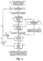
- step 40 If, in step 36 and 37, the signal processor 24 determines that the threshold has been exceeded for the specified count, in step 40 it sets a flag for the instant station in the "Station Alarm" mode.
- the conditions of the signal from the instant station i for which the receiver will signal a Station Alarm condition are:
- step 41 the processor 24 determines whether or not signals for all ten stations have been processed. If not, step 42 increments the station counter and loop 43 returns the program to step 34 to select the next station.
- the various values determined by the processor 24 in each cycle are tabulated in Tables I and II.
- a sampling rate of 500 samples per second allows 50 samples for each of the ten stations.
- the moving sampling window of 5 minutes will accommodate 15,000 samples for each station.
- step 44 determines whether or not any of the stations are in the "Station Alarm” mode. If none are, step 45 resets the station counter to " 1 " and loop 46 returns the program to step 34 to repeat the cycle.
- the processor 24 records the statistical values for the ten stations as shown in Table III below:
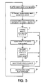
- step 50 the common processor 4 detects a Station Alarm condition for a particular station i in the Station Alarm status bits for zone N and checks the alarm status of the same station i for the adjacent zones N-1 and N+1 . Decision step 51 determines whether or not the station alarm for a particular station i is reported for the particular zone N alone. If it is not, i.e.
- step 51 determines that neither of the adjacent zones shows a simultaneous alarm for station i
- step 52 sets a Station Alarm flag for station i and zone N .
- Zone N Station Alarm 1, where M is the number of stations to a maximum of 10.
- step 53 the processor 4 determines whether or not more than 50 per cent of the station alarms for zone N are showing an alarm condition simultaneously. If they are not, the program returns to step 51 and processor 4 does not generate a SYSTEM INTRUDER ALARM signal for zone N. If step 52 indicates that more than 50 per cent of the station alarms for zone N indicate an alarm condition, step 54 generates a SYSTEM INTRUDER ALARM signal for zone N indicating that an intruder has been detected within zone N.
- the processor 24 may be preprogrammed with sets of values of sensitivity T, consecutive count X, and so on per zone N for each of a number of typical applications.
- the user may select one of the applications.
- the individual values may then be adjusted to take account of data collected during operation of the system.
- the adjustment may be effected by sending control signals to the microcontrollers via the cables.
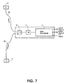
- the intrusion detection systems of Figures 6 and 7 could have one or more of the leaky cable sensors replaced by a localized antenna connected directly to the common processor 4.
- the antenna will serve as a single-point-in-space sensor to detect presence of an intruder.
- the common processor 4 will process signals from both the leaky cable(s) and the antenna in much the same way.
- the embodiment illustrated in Figure 8 comprises receivers 3 and three-port receivers 3' connected to leaky cables in an arbitrary network topography.
- Receivers 3 are similar to those in Figure 1 and connect single sensor cables in a bus configuration, as in the embodiment of Figure 1.
- Three-port receivers 3' connect three cables together at a T-junction.
- the three-port receivers 3' may be duplicate circuitry to accommodate the additional port, or use multiplexing.
- the first receiver 3A is connected to the common processor 4 by a feedline 6 as before. As before, the common processor 4 supplies DC power to the receivers via the intervening sensor cables and feedlines and receives their Station Alarm signals via the same route.
- such a FM receiver 3" and antenna 58 could be mounted directly upon an article 62 to be protected to detect any motion of the article 62 itself in addition to motion of someone approaching it.
- the receiver 3" has a DC input terminal 63 and an antenna 58 distributed around the article 62 which serves as both a sensor to receive the FM broadcast and control signals and a transmitting antenna for communicating Station Alarm signals to the common processor 4, which has an antenna 64 for receiving Station Alarm signals and transmitting control signals to the receiver 3".
- one or more cameras may be associated with one or more of the sensor zones to provide video surveillance in combination with the intrusion detection by leaky cables, enabling false alarms to be determined by the video surveillance systems.
- the detection sensitivity may be increased as compared with a stand-alone system.
Landscapes
- Physics & Mathematics (AREA)
- Electromagnetism (AREA)
- General Physics & Mathematics (AREA)
- Burglar Alarm Systems (AREA)
- Alarm Systems (AREA)
Claims (10)
- Un système de détection d'intrusion caractérisé par une pluralité de capteurs (2A...2X) couplé à une pluralité correspondante de récepteurs (3A...3X), chaque récepteur présentant des moyens (11-24) pour recevoir, à partir du capteur qui y est couplé, un signal à fréquence radio présentant une multiplicité de transmission à des fréquences différentes dans un spectre de fréquence prédéterminé, le récepteur étant agencé pour détecter ladite multiplicité de transmissions et présentant des moyens de calcul (24) pour déterminer périodiquement, pour chacune de ladite multiplicité de transmissions, une mesure d'amplitude du signal correspondant, pour comparer chaque mesure d'amplitude de signal pour chacune des fréquences différentes avec au moins une valeur de seuil préfixée et, si l'amplitude dépasse la valeur de seuil pendant une période de temps prédéterminée, pour indiquer une condition d'alarme potentielle, le système comprenant en outre des moyens (4) pour surveiller les récepteurs pour la présence des conditions d'alarme potentielle, et pour signaler une condition réelle d'alarme dans le cas où au moins un des récepteurs indique des conditions d'alarme potentielle pour un nombre prédéterminé de différentes fréquences de transmission pendant la même période de temps.
- Un système de détection d'intrusion selon la revendication 1, caractérisé en ce que chaque récepteur comprend des moyens (17, 18, 19) pour balayer un spectre radio FM et pour sélectionner un nombre desdites fréquences de transmission, et les moyens de calcul (24) sont agencés pour échantillonner l'amplitude du signal radio FM reçu à partir du capteur associé pendant un intervalle de temps prédéterminé, chaque échantillon constituant ladite mesure d'amplitude de signal, pour obtenir des statistiques pour une pluralité desdits échantillons sur chacune des périodes de temps successives, et pour régler périodiquement la valeur de seuil préfixée en fonction desdites statistiques.
- Un système de détection d'intrusion selon la revendication 2, caractérisé en ce que les moyens de calcul (24) sont agencés pour comparer chaque mesure d'amplitude du signal avec une valeur de seuil supérieure préfixée et une valeur de seuil inférieure préfixée, pour déterminer des valeurs de variance supérieure et inférieure pour la pluralité d'échantillons d'amplitude, pour mettre à jour les seuils supérieur et inférieur en fonction de la variance supérieure et inférieure respectivement, et pour indiquer ladite condition d'alarme potentielle dans le cas où un nombre prédéterminé desdits échantillons d'amplitude se trouve en dehors d'une plage définie par les seuils supérieur et inférieure.
- Un système de détection d'intrusion selon la revendication 1, caractérisé en ce que les moyens de surveillance (4) comprennent une unité processeur présentant des moyens pour recevoir des données concernant lesdites conditions d'alarme potentielle à partir desdits récepteur (3A...3X), les récepteurs présentant chacun des moyens (24,25,26) pour transmettre lesdites données à l'unité processeur (4), l'unité processeur étant agencée pour signaler ladite condition d'alarme réelle lorsque des conditions d'alarme potentielle signalées par un récepteur particulier se présente pour au moins une proportion prédéterminée de ladite multiplicité de transmissions pendant un intervalle de temps prédéterminé.
- Un système de détection d'intrusion selon la revendication 1, caractérisé en ce que les moyens de surveillance (4) comprennent un processeur commun (4) pour comparer des états de conditions d'alarme potentielle pour un capteur particulier avec des états de conditions d'alarme potentielle d'au moins un capteur immédiatement avoisinant, et pour déterminer l'existence d'une intrusion dans le cas où la condition d'alarme potentielle pour ladite station particulière ne coïncide pas avec un signal d'alarme pour ledit au moins un capteur immédiatement avoisinant.
- Un système de détection d'intrusion selon la revendication 5, caractérisé en ce chaque capteur (3A...3X) comprend une ligne de transmission ouverte, un premier récepteur (3A) étant connecté au processeur commun (4) pour traiter des signaux originaires des différents récepteurs, chacun des récepteurs ultérieurs (3B...3X) réalisant l'interconnexion de deux des lignes de transmission ouvertes, chaque récepteur étant agencé pour relier des signaux d'alarme d'intrusion potentielle à partir des récepteurs ultérieurs vers le processeur commun au moven de l'une quelconque des lignes de transmission ouvertes et récepteurs intervenants.
- Un système de détection d'intrusion selon la revendication 6, caractérisé en ce que le processeur commun (4) est agencé pour alimenter en énergie les récepteurs au moyen de la ligne de transmission intervenante.
- Un système de détection d'intrusion selon la revendication 1, caractérisé en ce que au moins un des capteurs comprend une antenne localisée (58),
- Un système de détection d'intrusion selon la revendication 1, caractérisé en ce que les récepteurs sont agencés selon une pluralité de sous-systèmes (S1...SM) comprenant chacun au moins un des récepteurs, et dans lequel les moyens de surveillance comprennent un processeur commun (4), les sous-systèmes étant séparés physiquement l'un de l'autre, les sous-systèmes et le processeur commun présentant des émetteurs-récepteurs respectifs pour communiquer des signaux d'alarme à partir de chaque sous-système vers le processeur commun.
- Un système de détection d'intrusion selon la revendication 1, caractérisé en ce que ledit spectre de fréquence prédéterminé est d'environ 88 MHz. à 108 MHz.
Applications Claiming Priority (3)
| Application Number | Priority Date | Filing Date | Title |
|---|---|---|---|
| CA002165384A CA2165384C (fr) | 1995-12-15 | 1995-12-15 | Systeme de detection d'intrusions a ligne de transmission ouverte utilisant l'analyse spectrale |
| CA2165384 | 1995-12-15 | ||
| PCT/CA1996/000840 WO1997022955A2 (fr) | 1995-12-15 | 1996-12-13 | Systeme de detection d'intrusions a ligne de transmission ouverte, faisant appel a l'analyse du spectre des frequences |
Publications (2)
| Publication Number | Publication Date |
|---|---|
| EP0886841A2 EP0886841A2 (fr) | 1998-12-30 |
| EP0886841B1 true EP0886841B1 (fr) | 2002-06-05 |
Family
ID=4157175
Family Applications (1)
| Application Number | Title | Priority Date | Filing Date |
|---|---|---|---|
| EP96940968A Expired - Lifetime EP0886841B1 (fr) | 1995-12-15 | 1996-12-13 | Systeme de detection d'intrusions a ligne de transmission ouverte, faisant appel a l'analyse du spectre des frequences |
Country Status (7)
| Country | Link |
|---|---|
| US (1) | US6288640B1 (fr) |
| EP (1) | EP0886841B1 (fr) |
| AU (1) | AU1028197A (fr) |
| CA (1) | CA2165384C (fr) |
| DE (1) | DE69621653D1 (fr) |
| IL (1) | IL124928A0 (fr) |
| WO (1) | WO1997022955A2 (fr) |
Families Citing this family (59)
| Publication number | Priority date | Publication date | Assignee | Title |
|---|---|---|---|---|
| CA2207119A1 (fr) * | 1997-06-06 | 1998-12-06 | Andre Gagnon | Systeme de detection effraction se servant de la detection de signaux sur bandes peu utilisees |
| JP3703689B2 (ja) * | 2000-06-01 | 2005-10-05 | 三菱電機株式会社 | 支障物検知装置及び支障物検知システム |
| US6577236B2 (en) * | 2000-09-05 | 2003-06-10 | Robert Keith Harman | FM CW cable guided intrusion detection radar |
| US6876103B2 (en) * | 2000-12-29 | 2005-04-05 | General Electric Company | Automatic transfer switch systems and controllers |
| JP3603825B2 (ja) * | 2001-08-27 | 2004-12-22 | オムロン株式会社 | 監視システム、中央監視装置、および車載監視装置 |
| US6750624B2 (en) | 2001-10-17 | 2004-06-15 | Delphi Technologies, Inc. | Non-contact obstacle detection system utilizing ultra sensitive capacitive sensing |
| CA2408573C (fr) | 2001-10-17 | 2011-12-20 | Andre Gagnon | Systeme de detection d'intrus ou d'evades |
| US6777958B2 (en) * | 2001-10-17 | 2004-08-17 | Delphi Technologies, Inc. | Method and apparatus for detecting a change in capacitance of a capacitive proximity sensor |
| US6723933B2 (en) | 2001-10-17 | 2004-04-20 | Ronald Helmut Haag | Flexible capacitive strip for use in a non-contact obstacle detection system |
| US6700393B2 (en) | 2001-10-17 | 2004-03-02 | Delphi Technologies, Inc. | Capacitive sensor assembly for use in a non-contact obstacle detection system |
| WO2004003591A1 (fr) | 2002-06-26 | 2004-01-08 | It-Højskolen | Procede et systeme de surveillance d'un environnement utilisant des ondes electromagnetiques |
| US7088236B2 (en) * | 2002-06-26 | 2006-08-08 | It University Of Copenhagen | Method of and a system for surveillance of an environment utilising electromagnetic waves |
| US7154391B2 (en) * | 2003-07-28 | 2006-12-26 | Senstar-Stellar Corporation | Compact security sensor system |
| US7551137B2 (en) * | 2004-06-10 | 2009-06-23 | Tektrap Systems Inc. | Apparatus and method for tracing a path travelled by an entity or object, and tag for use therewith |
| US20070149139A1 (en) * | 2004-06-10 | 2007-06-28 | Jean-Louis Gauvreau | Wireless Network System with Energy Management |
| CA2495357A1 (fr) * | 2004-06-10 | 2005-12-10 | Newtrax Technologies Inc. | Dispositif, systeme et methode de detection rf volumetrique d'intrusion |
| JP4587953B2 (ja) * | 2005-12-28 | 2010-11-24 | 三菱電機株式会社 | 侵入者検知システム |
| JP4667237B2 (ja) * | 2005-12-28 | 2011-04-06 | 三菱電機株式会社 | 侵入者検知装置 |
| US7446654B2 (en) * | 2006-03-09 | 2008-11-04 | Honeywell International Inc. | Monitored voltage inverter for security system |
| US7450006B1 (en) * | 2006-04-06 | 2008-11-11 | Doyle Alan T | Distributed perimeter security threat confirmation |
| US7688202B1 (en) * | 2006-04-06 | 2010-03-30 | Kelly Research Corp. | Distributed perimeter security threat determination |
| US8456304B2 (en) * | 2006-07-12 | 2013-06-04 | Intelligent Automation, Inc. | Perimeter security system |
| US7881882B2 (en) * | 2006-09-25 | 2011-02-01 | Ut-Battelle, Llc | Apparatus and method for detecting tampering in flexible structures |
| US20080079572A1 (en) * | 2006-09-28 | 2008-04-03 | Zohar Tsaba | Apparatus and method for using a wireless network as a motion detection system |
| JP2008263302A (ja) * | 2007-04-10 | 2008-10-30 | Mitsubishi Electric Corp | 侵入検知システム |
| JP4353989B2 (ja) * | 2007-04-27 | 2009-10-28 | 三菱電機株式会社 | 侵入検知システム |
| US7852197B2 (en) * | 2007-06-08 | 2010-12-14 | Sensomatic Electronics, LLC | System and method for inhibiting detection of deactivated labels using detection filters having an adaptive threshold |
| US8081074B2 (en) * | 2007-09-11 | 2011-12-20 | Marshall Jack L | Security system for protecting construction site assets |
| JP4573866B2 (ja) * | 2007-12-17 | 2010-11-04 | 三菱電機株式会社 | 侵入検知システム |
| US8595514B2 (en) | 2008-01-22 | 2013-11-26 | Verifone, Inc. | Secure point of sale terminal |
| US9013336B2 (en) | 2008-01-22 | 2015-04-21 | Verifone, Inc. | Secured keypad devices |
| DE102008031923A1 (de) * | 2008-07-08 | 2010-01-14 | Hochschule Ostwestfalen-Lippe | Verfahren für die Überwachung eines Raums |
| US7777496B2 (en) * | 2008-07-18 | 2010-08-17 | The United States Of America As Represented By The Secretary Of The Army | Remote sensor system for monitoring the condition of earthen structure and method of its use |
| US8432300B2 (en) * | 2009-03-26 | 2013-04-30 | Hypercom Corporation | Keypad membrane security |
| US8358218B2 (en) | 2010-03-02 | 2013-01-22 | Verifone, Inc. | Point of sale terminal having enhanced security |
| US8330606B2 (en) | 2010-04-12 | 2012-12-11 | Verifone, Inc. | Secure data entry device |
| US8779921B1 (en) * | 2010-05-14 | 2014-07-15 | Solio Security, Inc. | Adaptive security network, sensor node and method for detecting anomalous events in a security network |
| US8405506B2 (en) | 2010-08-02 | 2013-03-26 | Verifone, Inc. | Secure data entry device |
| US8593824B2 (en) | 2010-10-27 | 2013-11-26 | Verifone, Inc. | Tamper secure circuitry especially for point of sale terminal |
| US8621235B2 (en) | 2011-01-06 | 2013-12-31 | Verifone, Inc. | Secure pin entry device |
| US9183713B2 (en) | 2011-02-22 | 2015-11-10 | Kelly Research Corp. | Perimeter security system |
| US8884757B2 (en) | 2011-07-11 | 2014-11-11 | Verifone, Inc. | Anti-tampering protection assembly |
| US9691066B2 (en) | 2012-07-03 | 2017-06-27 | Verifone, Inc. | Location-based payment system and method |
| US10652253B2 (en) | 2013-03-15 | 2020-05-12 | CyberSecure IPS, LLC | Cable assembly having jacket channels for LEDs |
| US9160758B2 (en) | 2013-03-15 | 2015-10-13 | Stephen SOHN | Method and system for protective distribution system (PDS) and infrastructure protection and management |
| GB201306204D0 (en) * | 2013-04-05 | 2013-05-22 | Winkelmann Uk Ltd | Methods and apparatus for logging radio frequency spectrum data |
| US9213869B2 (en) | 2013-10-04 | 2015-12-15 | Verifone, Inc. | Magnetic stripe reading device |
| US20160026275A1 (en) | 2014-07-23 | 2016-01-28 | Verifone, Inc. | Data device including ofn functionality |
| US9595174B2 (en) | 2015-04-21 | 2017-03-14 | Verifone, Inc. | Point of sale terminal having enhanced security |
| US9763095B2 (en) | 2015-09-25 | 2017-09-12 | Harris Corporation | Managed access system that determines authorized and unauthorized mobile wireless devices |
| US9736706B2 (en) | 2015-09-25 | 2017-08-15 | Harris Corporation | Managed access system with monitoring device to determine system operability |
| US9769666B2 (en) | 2015-09-25 | 2017-09-19 | Harris Corporation | Managed access system with monitoring device to determine and change radio equipment |
| US9584252B1 (en) | 2015-09-25 | 2017-02-28 | Harris Corporation | Managed access system with mobile wireless device geolocation capability |
| US9820150B2 (en) | 2015-09-25 | 2017-11-14 | Harris Corporation | Managed access system having filtered communications using network interface device |
| US9681360B1 (en) | 2016-05-13 | 2017-06-13 | Harris Corporation | Managed access system that provides selective communications and registration of mobile wireless devices |
| US10284559B2 (en) | 2016-05-13 | 2019-05-07 | Harris Corporation | Managed access system with security assessment equipment |
| US10405184B2 (en) | 2017-01-31 | 2019-09-03 | Harris Corporation | Mobile wireless device managed access system providing enhanced authentication features and related methods |
| RU2645598C1 (ru) * | 2017-01-31 | 2018-02-21 | "Войсковая Часть 2337" | Способ охранного мониторинга с применением линейного радиоволнового средства обнаружения |
| US10544923B1 (en) | 2018-11-06 | 2020-01-28 | Verifone, Inc. | Devices and methods for optical-based tamper detection using variable light characteristics |
Family Cites Families (7)
| Publication number | Priority date | Publication date | Assignee | Title |
|---|---|---|---|---|
| US3163861A (en) | 1962-05-02 | 1964-12-29 | Suter Henry | Electromagnetic field disturbance intruder detection apparatus |
| CA1216340A (fr) | 1982-05-14 | 1987-01-06 | Dale R. Younge | Detecteur d'effraction |
| US4684929A (en) * | 1985-10-17 | 1987-08-04 | Ball Corporation | Microwave/seismic security system |
| GB2182474B (en) * | 1985-10-29 | 1989-09-20 | Shorrock Security Systems Ltd | Signal processing |
| DE3917897A1 (de) * | 1989-06-01 | 1990-12-06 | Hilmar Dipl Ing Reichel | Geraet zum erzeugen von steuersignalen durch einstrahlung von drahtlos-funk-sendern |
| AU4939293A (en) * | 1992-09-11 | 1994-04-12 | Instantel Inc. | Intrusion detection system |
| US5570079A (en) * | 1995-04-24 | 1996-10-29 | Dockery; Devan | Home security system for detecting an intrusion into a monitored area by an infrared detector |
-
1995
- 1995-12-15 CA CA002165384A patent/CA2165384C/fr not_active Expired - Fee Related
-
1996
- 1996-12-13 WO PCT/CA1996/000840 patent/WO1997022955A2/fr not_active Ceased
- 1996-12-13 IL IL12492896A patent/IL124928A0/xx unknown
- 1996-12-13 DE DE69621653T patent/DE69621653D1/de not_active Expired - Lifetime
- 1996-12-13 EP EP96940968A patent/EP0886841B1/fr not_active Expired - Lifetime
- 1996-12-13 AU AU10281/97A patent/AU1028197A/en not_active Abandoned
- 1996-12-13 US US09/077,980 patent/US6288640B1/en not_active Expired - Lifetime
Also Published As
| Publication number | Publication date |
|---|---|
| DE69621653D1 (de) | 2002-07-11 |
| WO1997022955A3 (fr) | 1997-08-21 |
| EP0886841A2 (fr) | 1998-12-30 |
| US6288640B1 (en) | 2001-09-11 |
| AU1028197A (en) | 1997-07-14 |
| IL124928A0 (en) | 1999-01-26 |
| WO1997022955A2 (fr) | 1997-06-26 |
| CA2165384C (fr) | 2008-04-01 |
| CA2165384A1 (fr) | 1997-06-16 |
Similar Documents
| Publication | Publication Date | Title |
|---|---|---|
| EP0886841B1 (fr) | Systeme de detection d'intrusions a ligne de transmission ouverte, faisant appel a l'analyse du spectre des frequences | |
| US8456304B2 (en) | Perimeter security system | |
| CA1216340A (fr) | Detecteur d'effraction | |
| US8232878B2 (en) | Perimeter security system | |
| US6954171B2 (en) | Method and apparatus for physical layer radar pulse detection and estimation | |
| US4101836A (en) | Sectored antenna receiving system | |
| CN1104175C (zh) | 用于选择无线系统的基站的天线射束的方法和系统 | |
| WO2003088532A1 (fr) | Systeme de detection d'intrusion pour reseaux sans fil | |
| SK164498A3 (en) | Method of transmitting and receiving data, system and receiver therefor | |
| US6424259B1 (en) | Intruder/escapee detection system and method using a distributed antenna and an array of discrete antennas | |
| JPH06343066A (ja) | スペクトラム拡散無線通信方式 | |
| CA2207119A1 (fr) | Systeme de detection effraction se servant de la detection de signaux sur bandes peu utilisees | |
| US5187808A (en) | Repeater site failure detector in communication system | |
| US20100246556A1 (en) | Communication method and apparatus | |
| JPH07231483A (ja) | 無線データ通信システム | |
| EP3543976B1 (fr) | Procédé permettant d'augmenter la spécificité de la détection de brouillage dans un système d'alarme domestique | |
| JP2943891B2 (ja) | 移動通信用一周波数交互通信方式におけるダイバーシチ方式 | |
| US5708964A (en) | Paging satelite line receiver having automatic signal acquisition | |
| US6201472B1 (en) | Wireless communication system with increased dynamic range | |
| AU2004305621B2 (en) | Method for monitoring the time synchronisation of emitters in a common wave network | |
| McHenry | A Hybrid DoD ENG 2025-2110 MHz Band Spectrum Sharing Approach | |
| JP2011033345A (ja) | 侵入者検知装置 | |
| US20040171957A1 (en) | Method of attenuating the influence on UWB communications of interference produced by bursty radio transmission systems | |
| Harrington et al. | Concepts and applications of wireless security systems for tactical, portable, and fixed sites | |
| EP3540707B1 (fr) | Procédé et dispositif de détection de perturbations radio dans un système de radiocommunication |
Legal Events
| Date | Code | Title | Description |
|---|---|---|---|
| PUAI | Public reference made under article 153(3) epc to a published international application that has entered the european phase |
Free format text: ORIGINAL CODE: 0009012 |
|
| 17P | Request for examination filed |
Effective date: 19980928 |
|
| AK | Designated contracting states |
Kind code of ref document: A2 Designated state(s): DE FR GB IT |
|
| 17Q | First examination report despatched |
Effective date: 19990312 |
|
| GRAG | Despatch of communication of intention to grant |
Free format text: ORIGINAL CODE: EPIDOS AGRA |
|
| GRAG | Despatch of communication of intention to grant |
Free format text: ORIGINAL CODE: EPIDOS AGRA |
|
| GRAH | Despatch of communication of intention to grant a patent |
Free format text: ORIGINAL CODE: EPIDOS IGRA |
|
| GRAH | Despatch of communication of intention to grant a patent |
Free format text: ORIGINAL CODE: EPIDOS IGRA |
|
| GRAA | (expected) grant |
Free format text: ORIGINAL CODE: 0009210 |
|
| AK | Designated contracting states |
Kind code of ref document: B1 Designated state(s): DE FR GB IT |
|
| PG25 | Lapsed in a contracting state [announced via postgrant information from national office to epo] |
Ref country code: IT Free format text: LAPSE BECAUSE OF FAILURE TO SUBMIT A TRANSLATION OF THE DESCRIPTION OR TO PAY THE FEE WITHIN THE PRESCRIBED TIME-LIMIT;WARNING: LAPSES OF ITALIAN PATENTS WITH EFFECTIVE DATE BEFORE 2007 MAY HAVE OCCURRED AT ANY TIME BEFORE 2007. THE CORRECT EFFECTIVE DATE MAY BE DIFFERENT FROM THE ONE RECORDED. Effective date: 20020605 |
|
| REG | Reference to a national code |
Ref country code: GB Ref legal event code: FG4D |
|
| REF | Corresponds to: |
Ref document number: 69621653 Country of ref document: DE Date of ref document: 20020711 |
|
| DIN2 | Information on inventor provided after grant (deleted) | ||
| RIN2 | Information on inventor provided after grant (corrected) |
Free format text: GAGNON, ANDRE |
|
| PG25 | Lapsed in a contracting state [announced via postgrant information from national office to epo] |
Ref country code: DE Free format text: LAPSE BECAUSE OF FAILURE TO SUBMIT A TRANSLATION OF THE DESCRIPTION OR TO PAY THE FEE WITHIN THE PRESCRIBED TIME-LIMIT Effective date: 20020906 |
|
| ET | Fr: translation filed | ||
| PLBE | No opposition filed within time limit |
Free format text: ORIGINAL CODE: 0009261 |
|
| STAA | Information on the status of an ep patent application or granted ep patent |
Free format text: STATUS: NO OPPOSITION FILED WITHIN TIME LIMIT |
|
| 26N | No opposition filed |
Effective date: 20030306 |
|
| REG | Reference to a national code |
Ref country code: GB Ref legal event code: 732E |
|
| REG | Reference to a national code |
Ref country code: FR Ref legal event code: TP |
|
| PGFP | Annual fee paid to national office [announced via postgrant information from national office to epo] |
Ref country code: FR Payment date: 20101224 Year of fee payment: 15 |
|
| PGFP | Annual fee paid to national office [announced via postgrant information from national office to epo] |
Ref country code: GB Payment date: 20101208 Year of fee payment: 15 |
|
| GBPC | Gb: european patent ceased through non-payment of renewal fee |
Effective date: 20111213 |
|
| REG | Reference to a national code |
Ref country code: FR Ref legal event code: ST Effective date: 20120831 |
|
| PG25 | Lapsed in a contracting state [announced via postgrant information from national office to epo] |
Ref country code: GB Free format text: LAPSE BECAUSE OF NON-PAYMENT OF DUE FEES Effective date: 20111213 |
|
| PG25 | Lapsed in a contracting state [announced via postgrant information from national office to epo] |
Ref country code: FR Free format text: LAPSE BECAUSE OF NON-PAYMENT OF DUE FEES Effective date: 20120102 |