EP0886939B1 - Effiziente paketvermittlung mit ausgangsanforderung und verfahren - Google Patents
Effiziente paketvermittlung mit ausgangsanforderung und verfahren Download PDFInfo
- Publication number
- EP0886939B1 EP0886939B1 EP97915038A EP97915038A EP0886939B1 EP 0886939 B1 EP0886939 B1 EP 0886939B1 EP 97915038 A EP97915038 A EP 97915038A EP 97915038 A EP97915038 A EP 97915038A EP 0886939 B1 EP0886939 B1 EP 0886939B1
- Authority
- EP
- European Patent Office
- Prior art keywords
- packet
- connection
- ingress
- port
- packets
- Prior art date
- Legal status (The legal status is an assumption and is not a legal conclusion. Google has not performed a legal analysis and makes no representation as to the accuracy of the status listed.)
- Expired - Lifetime
Links
- 238000000034 method Methods 0.000 title claims description 31
- 230000015654 memory Effects 0.000 claims description 63
- 230000022131 cell cycle Effects 0.000 claims description 30
- 239000004744 fabric Substances 0.000 claims description 10
- 238000012546 transfer Methods 0.000 claims description 10
- 230000001360 synchronised effect Effects 0.000 claims description 7
- 230000005540 biological transmission Effects 0.000 claims description 5
- 238000002372 labelling Methods 0.000 claims description 3
- 230000037361 pathway Effects 0.000 description 33
- 238000010586 diagram Methods 0.000 description 18
- 239000000872 buffer Substances 0.000 description 7
- 238000004891 communication Methods 0.000 description 4
- 230000008569 process Effects 0.000 description 4
- 230000007246 mechanism Effects 0.000 description 3
- 238000012545 processing Methods 0.000 description 3
- 230000003111 delayed effect Effects 0.000 description 2
- 238000013461 design Methods 0.000 description 2
- 238000012986 modification Methods 0.000 description 2
- 230000004048 modification Effects 0.000 description 2
- 238000012544 monitoring process Methods 0.000 description 2
- 240000003537 Ficus benghalensis Species 0.000 description 1
- 230000004075 alteration Effects 0.000 description 1
- 238000013459 approach Methods 0.000 description 1
- 230000006399 behavior Effects 0.000 description 1
- 230000000903 blocking effect Effects 0.000 description 1
- 230000001419 dependent effect Effects 0.000 description 1
- 238000005516 engineering process Methods 0.000 description 1
- 230000007774 longterm Effects 0.000 description 1
- 239000000203 mixture Substances 0.000 description 1
- 230000006855 networking Effects 0.000 description 1
- 238000011084 recovery Methods 0.000 description 1
- 230000004044 response Effects 0.000 description 1
- 238000000638 solvent extraction Methods 0.000 description 1
- 238000012384 transportation and delivery Methods 0.000 description 1
Images


Classifications
-
- H—ELECTRICITY
- H04—ELECTRIC COMMUNICATION TECHNIQUE
- H04L—TRANSMISSION OF DIGITAL INFORMATION, e.g. TELEGRAPHIC COMMUNICATION
- H04L12/00—Data switching networks
- H04L12/54—Store-and-forward switching systems
- H04L12/56—Packet switching systems
- H04L12/5601—Transfer mode dependent, e.g. ATM
-
- H—ELECTRICITY
- H04—ELECTRIC COMMUNICATION TECHNIQUE
- H04L—TRANSMISSION OF DIGITAL INFORMATION, e.g. TELEGRAPHIC COMMUNICATION
- H04L49/00—Packet switching elements
- H04L49/10—Packet switching elements characterised by the switching fabric construction
- H04L49/104—Asynchronous transfer mode [ATM] switching fabrics
- H04L49/105—ATM switching elements
- H04L49/107—ATM switching elements using shared medium
-
- H—ELECTRICITY
- H04—ELECTRIC COMMUNICATION TECHNIQUE
- H04L—TRANSMISSION OF DIGITAL INFORMATION, e.g. TELEGRAPHIC COMMUNICATION
- H04L49/00—Packet switching elements
- H04L49/30—Peripheral units, e.g. input or output ports
- H04L49/3081—ATM peripheral units, e.g. policing, insertion or extraction
- H04L49/309—Header conversion, routing tables or routing tags
-
- H—ELECTRICITY
- H04—ELECTRIC COMMUNICATION TECHNIQUE
- H04L—TRANSMISSION OF DIGITAL INFORMATION, e.g. TELEGRAPHIC COMMUNICATION
- H04L12/00—Data switching networks
- H04L12/54—Store-and-forward switching systems
- H04L12/56—Packet switching systems
- H04L12/5601—Transfer mode dependent, e.g. ATM
- H04L2012/5672—Multiplexing, e.g. coding, scrambling
- H04L2012/5674—Synchronisation, timing recovery or alignment
-
- H—ELECTRICITY
- H04—ELECTRIC COMMUNICATION TECHNIQUE
- H04L—TRANSMISSION OF DIGITAL INFORMATION, e.g. TELEGRAPHIC COMMUNICATION
- H04L12/00—Data switching networks
- H04L12/54—Store-and-forward switching systems
- H04L12/56—Packet switching systems
- H04L12/5601—Transfer mode dependent, e.g. ATM
- H04L2012/5678—Traffic aspects, e.g. arbitration, load balancing, smoothing, buffer management
- H04L2012/5679—Arbitration or scheduling
Definitions
- the present invention relates generally to packet communication networks for transmitting a digitally coded packet, and more particularly, to efficient packet switching in a packet communication network.
- Packet switching is a technology for networking systems in which data from a plurality of users is divided into units called packets and transmitted over a common transmission line. Packet switching differs from circuit switching in that packet switching uses bandwidth allocated dynamically on demand across logical connections, as opposed to the long-term allocations of bandwidth provided in circuit switching. Packet switching can reduce costs to network users by providing better sharing of network resources than circuit switching. Packet switched service has the capability to handle any mixture of traffic types, such as voice, video, and data, simultaneously. It can also provide different classes of service, in terms of delay, jitter and probability of loss, to different connections.
- Packet communication networks consists of "nodes” which are devices for creating, accepting, or transferring packets, and "links" that connect two nodes.
- packet messages are digitally encoded at a source node for transmission over some sequence of links and nodes to a destination node of the network.
- FIG. 1 numeral 100, shows an abstract representation of a switch connecting N input links and N output links, each of rate R.
- the maximum throughput of the entire switch is less than or equal to N*R (102), (where "*" denotes multiplication).
- N*R 102
- the output link selected is dependent upon information contained in a preselected location within the packet.
- Three classes of packet switch designs known in the art are output-queued switches, input-queued switches, and shared-memory switches.
- FIG. 2 is a block diagram showing packet flows in a typical output-queued switch architecture as is known in the art.
- the processing performed on each packet by the switch has two parts: ingress processing in an ingress port (IP) (202, 204, 206, ...208), and egress processing in an egress port (EP) (226, 228, 230, ..., 232).
- IP ingress port
- EP egress port
- Packets arrive at IPs and are directed to a selected EP through a switch fabric (234) capable, for example, of delivering all arriving packets (rate N*R).
- FIG. 2 shows, for example, a shared-media switch fabric, though other types are possible (e.g., crosspoint, banyan).
- Address filters select the packets that are addressed to a particular EP.
- the selected packets are stored in, for example, first-in-first-out (FIFO) buffers (218, 220, 222, ..., 224), and then sent to egress ports (226, 228, 230, ..., 232).
- FIFO first-in-first-out
- FIFOs 318, 320, 322, ...324) receiving an output from one of a plurality of address filters (310, 312, 314, ...316) must be designed to accept packets at rate N*R, while packets are read out of FIFOs (326, 328, 330, ...332) at rate R.
- these FIFOs require the use of large, very high speed memories.
- FIG. 4 is a block diagram of a device having packet flows in a typical input-queued architecture as is known in the art.
- IPs 402, 404, 406, ..., 408
- EPs 426, 428, 430, ...432
- FIFOs 410, 412, 414, ..., 416)
- switch fabric e.g., shared-media fabric 434 with rate N*R.
- each EP can accept only one packet at a time.
- the arbitration blocks (418, 420, 422, ...
- FIFOs allow only one packet to be delivered; the rest are delayed or "blocked.”
- the FIFOs are used to store the delayed packets. This "head-of-line blocking" behavior causes significantly lower performance than the performance of output-queued switches.
- the FIFOs are only required to read and write data at rate R.
- US 5,001,706 describes a technique for connecting packet data through a system.
- EP-A-0 624 015 describes a system for transferring packets between multiple input and output ports.
- the present invention performs packet switching through a novel output-request mechanism.
- the invention results in packet switching performance comparable to output-queued switches, but with lower memory throughput requirements, and hence lower cost.
- FIG. 5 is a block diagram of one embodiment of a device having a packet switch architecture with packet flows in accordance with the present invention.
- Packets arrive at N ingress ports (IP)(502, 504, 506, ..., 508), are placed in buffers (510, 512, 514, ..., 516), are forwarded from the buffers to a switch fabric (e.g., shared bus 526), and are delivered to N egress ports (EP) (518, 520, 522, ..., 524).
- IP ingress ports
- EP egress ports
- Each ingress/egress port includes an ingress processor /egress processor with an associated memory wherein three pathways are utilized for packet switching.
- the pathways may be used, for example, time-shared buses and/or dedicated connections.
- EPs request packets from IPs, using control pathways to be described.
- IPs respond to requests by causing the requested packets to be read out of the associated buffer. If the rate of packet arrivals on each input link is R, then the rate that packets may be read out of each buffer is limited to k*R, (where k is a preselected integer less than or equal to N). If packets are requested from a given buffer at a rate greater than k*R, excess requests are refused. A refused request is repeated until the request is accepted.
- this output request architecture provides better throughput than input-queued switches.
- the switch throughput approaches that of output-queued architectures, and average queue lengths are smaller.
- this architecture provides high performance and reduces the cost of the buffer by reducing its transfer rate to k*R instead of N*R. Unlike the Knockout switch, however, no packets are lost.
- the total packet rate of the fabric need not be N*R.
- the total packet rate of the switch fabric is c*N*R, where c is a preselected value in the range from 0 to 1).
- the value c is chosen so that c*N*R is sufficient to support the average throughput requirements of the entire switch.
- FIG. 6 is a block diagram of a device having an efficient packet switch structure in accordance with the present invention.
- Each port has ingress ports (IP 0 ,..., IP N-1 ) (602, ..., 604) and egress ports (EP 0 , ..., EP N-1 ) (610, ..., 612); each IP of a plurality of IPs (602, ..., 604) is connected to an associated packet memory (606, ..., 608) that is used to store received packets, and each EP of a plurality of EPs (610, ...612) is connected to a corresponding tag memory (614, ..., 616) used to store information about the packets waiting in IPs to be delivered to the attached EP.
- N is a preselected integer indicating the number of ports in the switch.
- the ingress ports and egress ports are interconnected (618). Incoming packets arrive via IPs and outgoing packets leave via EPs.
- FIG. 7 shows one embodiment of a device in accordance with the present invention wherein the structure for the operation of transferring a packet from ingress to egress is shown in more detail.
- the steps shown include: A) determining, by a receiving IP (702, ...,704), a destination EP for a received packet in accordance with a first predetermined scheme and storing the received packet in a packet memory (706, ...,708) connected to the receiving IP; B) sending, by the receiving IP, to the destination EP, an arrival tag having at least a memory location and IP number indicating where the packet is stored; C) receiving, by a destination EP, the arrival tag/tags and storing the arrival tag/tags in a tag memory (714, ..., 716) connected to the destination EP (710, ..., 712); D) selecting, by the destination EP, a stored arrival tag in accordance with a second predetermined scheme, and sending the selected stored arrival tag back to the IP that sent the arrival tag to request transmission of the received packet associated with the arrival
- the IPs and EPs are interconnected via an arrival pathway (718, 818), a request pathway (720, 820) and a packet pathway (722, 822).
- a packet arrives at IP 1 and is stored (a) in an ingress packet memory (804).
- An arrival tag is sent (b) on the arrival pathway (818) and stored (c) in a tag memory (808) of EP 2 (806).
- the arrival tag is retrieved (d) from the tag memory (808) and, using the request pathway (820) is sent back (e) to IP 1 (802).
- IP 1 (802) sends (f) the requested packet on a packet pathway (822) to the destination EP.
- the pathways may be used, for example, time-shared buses and/or dedicated connections.
- the arrival tag may also include information for scheduling the packet in the destination EP.
- the EPs may organize tags, wherein the tags represent waiting packets, into multiple queues representing different connections, priorities, or qualities of service.
- step (e) of the operation of transferring a packet from ingress to egress where an IP may receive a plurality of arrival tags representing requests for packets from a plurality of EPs, in one implementation the IP may satisfy requests in accordance with a predetermined request rate and refuse requests exceeding the predetermined request rate. Where an EP's request is refused, the EP typically repeats the request after a predetermined time.
- a rate of packet requests allowed on the request pathway by the EPs may be restricted to a predetermined level that does not exceed the information rate of the packet pathway.
- FIG. 5 shows a switch in which the sum of the maximum rates of all the egress ports is N*R, but the packet pathway has a rate of only c*N*R.
- designing the packet pathway to handle such a reduced rate may lead to savings.
- One implementation of a mechanism for restricting the rate of requests from EPs to avoid requesting packets at a higher rate than the packet pathway can accommodate is given below.
- the efficient packet switch of the present invention may be synchronized into cell cycles by means of a centrally generated clock (CELLCLK) signal by a clock generator (918), where a cell cycle is a period of time during which no more than one packet arrives at each IP of a plurality of IPs (902, ..., 904), each IP generates only one arrival tag per cell cycle, and each EP of a plurality of EPs (906, ..., 908) generates only one request per cell cycle. Further, each EP transmits on the output link a maximum of one packet per cell cycle.
- Each EP has a START value register (910, ..., 914) and a SOURCE counter (912, ..., 916).
- the switch may utilize a predetermined arbitration scheme that, for each cell cycle, limits the number of requests accepted per IP to a preselected integer k associated with the IP, and limits the total number of requests accepted by all IPs to a predetermined integer M, where M ⁇ c*N.
- the predetermined limit k may be different for different IPs.
- the scheme is "distributed", meaning that it is performed by all IPs and EPs in parallel rather than by a central arbitration control unit.
- the predetermined synchronous arbitration scheme utilizes two timing signals:
- the REQUEST signal is sent on a request bus
- the ACKNOWLEDGE bit is sent on an acknowledge line connecting all IPs and EPs
- the SYNC bit is sent on a wired-OR SYNC line connecting all EPs.
- the steps of the arbitration method typically include:
- each EP has determined whether the EP's REQUEST will be satisfied and which EP will start the arbitration process in a next cell cycle.
- the entire arbitration process requires at least N + 1 cycles since the ACKNOWLEDGE bit lags by least one clock cycle behind the REQUEST signal.
- the switch typically includes N ingress ports and N egress ports with unique identification numbers, IDs, and having a request pathway from egress ports to ingress ports, and having an acknowledge line from ingress ports to egress ports.
- the steps of the predetermined arbitration scheme include: A) issuing, by each of a plurality of egress ports that have a current REQUEST, a REQUEST on the request pathway, wherein the REQUEST includes an VALID bit having values True and False, and a QPORT number specifying an ingress port ID, and wherein the REQUEST of the plurality of egress ports are issued one at a time in a predetermined sequence; and B) responding, subsequent to each REQUEST in which the VALID bit is True, by an ingress port with an ID matching the QPORT in the REQUEST, with an ACKNOWLEDGE bit of Accept or Reject based at least on whether the ingress port has already accepted k REQUESTs and on whether M REQUESTs have already been accepted in the current cell cycle,
- the N egress ports generally have unique arbitration sequence numbers from 0 to N-1, and in step A, REQUEST signals are issued in round-robin order of the arbitration sequence numbers, and upon a REQUEST from an egress port being rejected, the first egress port that issued a rejected REQUEST in the current cell cycle is used as a new starting point for the next cell cycle.
- all egress ports contain a START register and a SOURCE counter and the steps of the predetermined arbitration scheme include: A) maintaining a SOURCE counter by each egress port indicating the arbitration sequence number of the egress port currently making a REQUEST, and asserting a SYNC signal every time the egress port's SOURCE counter equals a predetermined value, and B) monitoring the SYNC signal by each egress port, and where the SYNC signal is asserted for more than one clock cycle in a cell cycle, resetting, by the egress port a START value to a preselected value, where the preselected value is the same for all egress ports.
- numeral 1100 where the switch has N ingress ports, IPs, and N egress ports, EPs, numbered from 0 to N-1, and has a cell cycle timing signal CELLCLK and a timing signal CLK, there are typically at least N+1 cycles of CLK per cycle of CELLCLK, CELLCLK signals and CLK signals are provided to all ingress ports and all egress ports of said switch, and all egress ports contain a CLOCK counter.
- the predetermined arbitration scheme includes the steps of: A) initializing (1102) all egress port START values to zero and proceeding to step B at a beginning of a next CELLCLK cycle; B) initializing (1104), in each egress port, EP, a CLOCK counter to 0 and copying, in each EP, the START value into a SOURCE counter, and proceeding to step H (1116); C) proceeding (1106), upon the VALID bit in a last REQUEST being True, to step D (1108), and otherwise to step F (1112) ; D) responding (1108), by an ingress port, on the acknowledge pathway, upon the ingress port's number matching the SPORT number in the last REQUEST, with an ACKNOWLEDGE bit of one of: Accept and Reject where the ACKNOWLEDGE bit is Reject if the IP already has accepted k REQUESTs or if M REQUESTs have already been accepted by any ingress port since a beginning of a current cell cycle, where a number of REQUESTs
- the arbitration scheme includes a recovery mechanism in case of error wherein the following step is added in step I prior to returning to step C at the beginning of the next cycle of CLK: asserting, by the EPs, a wired-OR SYNC signal when the EP's SOURCE counter value is equal to zero, and monitoring, by the EPs, the SYNC signal in each clock cycle, and where the SYNC signal is asserted for more than one clock cycle in a current cell cycle, setting the START value to zero and optionally asserting the SYNC signal for a remainder of the current cell cycle.
- the method for efficient switching of a plurality of packets from a plurality of ingress ports to a plurality of egress ports includes the steps of: A) storing (1202) the packets in memory; B) sending arrival information (1204) for each packet to a destination egress port for the packet; C) storing (1206), in memory of a controller at each destination egress port, the arrival information; D) requesting (1208), by the controller at each destination egress port, the packets from the packet memory in accordance with a predetermined scheme; and E) sending (1210), by the packet memory, to the destination egress ports, the packets requested.
- an ingress port sends packets requested at a rate up to a predetermined transfer rate and fails to send packets requested that require a transfer rate greater than the predetermined transfer rate, and where the packets fail to be sent, the destination egress ports re-request the packets that failed to be sent.
- the plurality of ingress ports are connected to the plurality of egress ports through a rate-limited switch fabric having a rate less than the sum of the maximum rates of all of the egress ports, but greater than the sum of the average rates of all of the egress ports.
- FIG. 13 is a block diagram of a device having packet flows in a typical shared-memory architecture as is known in the art.
- a shared-memory switch all packets arriving at IPs are transferred to a central packet memory (1302), and all packets delivered to EPs come from the central packet memory.
- the performance attained is similar to that of an output-queued switch, but to support N input links and N output links at rate R, the packet memory must be designed to access packets at a very high rate, specifically, 2*N*R.
- FIG. 14 shows one embodiment of a device in accordance with the present invention, wherein packets are stored in a central shared memory.
- all packets arriving at IPs 1402, ..., 1404 are transferred to a central packet memory (1406), and all packets delivered to EPs (1408, ..., 1410) come from the central packet memory (1406).
- Each EP of a plurality of EPs 1408, ..., 1410) is connected to a corresponding tag memory (1412, ..., 1414) which is utilized as described above.
- N is a preselected integer indicating the number of ports in the switch.
- the packet memory must be designed to access packets at a rate of (1+c)*N*R where 0 ⁇ c ⁇ 1 and c is chosen large enough to support the average throughput requirements of the entire switch.
- output-request packet switching may be performed using a small connection table containing one entry per connection in place of the tag memory which may contain many tags per connection.
- FIG. 15 numeral 1500, shows one embodiment of a method for performing output-request packet switching in accordance with the present invention, in storing at most one tag per active connection.
- the method includes the following steps: First, where the EPs have initialized (1502) the ACTIVE bit to be equal to False for all connections, a received packet that arrives at an IP via an ingress port is stored (1504) in a queue in a memory, wherein each queue corresponds to an individual connection; Then, for each packet that arrives at the IP, the IP determines (1506) whether the packet has arrived at an empty queue, and where the packet has arrived at an empty queue, the IP generates (1508) an arrival tag that has a connection identifier code, and where selected, may also include scheduling information. Where the arrival tag is generated, the IP sends the arrival tag to a destination EP for the packet.
- the EP receives (1510) the arrival tag and records its arrival, typically by setting an ACTIVE bit in a connection table coupled to the EP, where the connection table has an ACTIVE bit for each connection that goes through the EP.
- the EP selects (1512), from among all the connections that have the ACTIVE bit set in the connection table, a connection in accordance with a predetermined scheme, clears the ACTIVE bit for the selected connection, and sends a request containing at least a connection identifier back to the IP that sent the arrival tag.
- the IP uses (1514) the connection identifier to locate the packet queue and dequeues a next packet, labels the packet with a MORE bit which is True if there are more packets remaining in the queue and False otherwise, and sends the packet to the requesting EP. Then, the EP receives (1516) the requested packet and transmits the packet from the associated egress port. Where the MORE bit in the packet is True (1518), the EP also sets (1520) the ACTIVE bit for the connection.
- the ingress port queue for connection "C" is initially empty, and then two packets arrive in rapid succession and are placed in this queue. Since the first packet arrives at an empty queue, an arrival tag is sent to the EP for connection C, causing the EP to set the ACTIVE bit for connection C True.
- the EP periodically selects connections that have the ACTIVE bit True, using a predetermined scheme. When the EP selects connection C, a request is sent to the IP for connection C. The IP then dequeues the first of the two packets, and sends it back to the EP. The MORE bit sent with the packet is set True, since another packet remains in the queue.
- Pipelining refers to a technique of partitioning a sequential process into subprocesses, with each subprocess being executed in a special dedicated module, and multiple nodules operating concurrently on different data elements (in this case, operating on different packets).
- the EP must request a packet and then wait for that packet to arrive before requesting the next one.
- the procedure may be modified to give the egress port information about the number of packets waiting that it can request. This can be done, for example, by keeping a sequence count of packets arrived at each connection at the ingress port, and whenever a packet is requested by the egress port, labeling the packet with the latest sequence count for the associated connection.
- the egress port also maintains a sequence count for each connection of packet requests it has issued.
- the egress port can compare its sequence count to the count in arriving packets to determine whether there are more packets waiting in the ingress queue.
- the method of the present invention may be implemented as follows. For each connection through an IP, there is an associated modulo sequence count value ARRIVSEQ, typically 1 to 4 bits long, where the modulo of ARRIVSEQ is S, and "#" denotes addition modulo S. Initially the ARRIVESEQ value for each connection is set to an arbitrary value. Also, coupled to the EP there is a connection table with an entry for each connection through the EP, containing at least an ACTIVE bit, a MANY bit, a REQSEQ value, and a LASTSEQ value, wherein REQSEQ and LASTSEQ values have the same number of bits as ARRIVSEQ.
- ARRIVSEQ, REQSEQ, and LASTSEQ may be viewed as packet sequence numbers, modulo S.
- the ARRIVSEQ value at the IP is the sequence number of the last packet that arrived.
- Each packet sent to the EP is accompanied by the newest ARRIVSEQ value, which is stored in the EP as LASTSEQ.
- LASTSEQ tells the EP the sequence number of the last request the EP will have to make.
- the EP keeps track of the sequence number of its current request in REQSEQ.
- REQSEQ catches up to LASTSEQ, the EP stops requesting packets. Since REQSEQ and LASTSEQ are modulo counts, they can be equal even though many packets may remain in the IP's queue, but in such cases the MANY bit keeps the EP from stopping.
- the EP periodically selects connections that have the ACTIVE bit True, using a predetermined scheme.
- REQSEQ is incremented to 1
- REQSEQ now equals LASTSEQ
- the ACTIVE bit for the connection is set False.
- a request is sent to the IP for connection C, and in response, the IP dequeues the first packet, and sends it back to the EP.
- the modulo S is selected to be greater than the number of packets that may be requested by an EP during the delay between request of a packet in step D and the packet being received in step F.
- modulo sequence counters described above are just one method of giving the EP information about how many unrequested packets remain in the queue. More generally, the method of the present invention is as follows:
- the IP For each connection through an IP, the IP has queue status information which is set to a first predetermined starting value, and for each connection through an EP, there is an entry in a connection table coupled to the EP, containing at least an ACTIVE indicator initially set to False, request status information initially set to a second predetermined starting value, and queue status information initially set to a first predetermined starting value.
- Packets arriving at the ingress ports are stored in packet queues, wherein each queue corresponds to an individual connection. Cells are switched from the ingress ports to the egress ports by means of the following steps:
- arrival information is recorded at the EPs by storing arrival tags, typically in a queuing arrangement, in addition to or instead of setting ACTIVE indicators in a connection table.
- the EPs store, at most, one tag per connection.
- numeral 1700 one embodiment operates by the following steps. First, a received packet that arrives at an IP via an ingress port is stored (1702) in a queue in a memory, wherein each queue corresponds to an individual connection.
- the IP determines (1704) whether the packet has arrived at an empty queue, and where the packet has arrived at an empty queue, the IP generates (1706) an arrival tag that has a connection identifier code, and where selected, may also include scheduling information and where the arrival tag is generated, the IP sends the arrival tag to a destination EP for the packet. Where the arrival tag is generated, the EP receives and stores (1708) the arrival tag. The EP selects (1710) a stored arrival tag in accordance with a predetermined scheme, e.g., removing the tag in a first-in-first-out order, and sends the arrival tag back to the IP that sent the arrival tag.
- a predetermined scheme e.g., removing the tag in a first-in-first-out order
- the IP uses (1712) the connection identifier to locate the packet queue and dequeues a next packet, labels the packet with a MORE bit which is True if there are more packets remaining in the queue, and False otherwise, and sends the packet to the requesting EP.
- the EP receives (1714) the requested packet and transmits (1716) the packet from the associated egress port. Where the MORE bit in the packet is True (1716), the EP generates (1718) an arrival tag corresponding to the next packet waiting and stores the arrival tag with other arrival tags.
- the above method may be modified for higher speed pipelined operation by giving the egress port information about the number of packets waiting that it can request.
- This implementation shown in FIG. 18 , numeral 1800, may be implemented as follows. For each connection through an IP, there is an associated modulo sequence count value ARRIVSEQ, typically 1 to 4 bits long, where the modulo of ARRIVSEQ is S, and "#" denotes addition modulo S. Initially the ARRIVESEQ value for each connection is set to an arbitrary value (1802).
- connection table with an entry for each connection through the EP, containing at least an ACTIVE bit, a MANY bit, a REQSEQ value, and a LASTSEQ value, wherein REQSEQ and LASTSEQ values have the same number of bits as ARRIVSEQ.
- the ACTIVE bit and the MANY bit for each connection are initially set to False. Packets are switched from ingress ports to egress ports by means of the following steps:
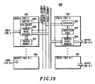
- FIG. 19 is a block diagram of one embodiment of a device in accordance with the present invention.
- the device provides efficient switching of a plurality of packets from a plurality of ingress ports to a plurality of egress ports in a connection-oriented network.
- the device includes: a plurality of ingress ports (1902, ..., 1904) , each including an ingress memory (1910, ...), an ingress queue manager (1908), ..., an arrival controller (1906, ...), and a plurality of egress ports (1912, ...,1914), each egress port including a connection table (1918, ...), a scheduler (1916, ...), and an egress packet handler (1920, ).
- the ingress memory (1910, %) is used for storing a queue of packets for each connection of a plurality of connections.
- the ingress queue manager (1908, %) is coupled to the ingress port memory (1910, 7)and is utilized for receiving packets from an input link, storing the packets in ingress memory, and for updating queue status information associated with the connection.
- the IP has queue status information for each connection that goes through the IP and, upon receiving a connection identifier from a scheduler (1916, ...) of an egress port, retrieving a packet from the corresponding queue in ingress memory , updating the queue status information for the connection, and sending to the destination egress ports the packet together with queue status information for determining, by the EP, whether packets remain in the packet queue that are unrequested by the EP.
- the arrival controller (1906, ...) is coupled to the ingress queue manager (1906, ...), and is used for, where the queue for a connection is empty when the packet arrives, sending an arrival tag containing at least a connection identifier to a destination egress port for the packet.
- the egress ports (1912, ...1914) are coupled to the ingress ports (1902, ..., 1904).
- the connection table (1918, 7) is used for storing, for each connection, at least an ACTIVE indicator, request status information, and queue status information.
- the scheduler (1916, %) is coupled to the connection table (1918, ...), and is used for receiving arrival tags sent by ingress ports and setting the corresponding ACTIVE indicators True in the connection table (1918); and for selecting connections that have the ACTIVE indicator set in accordance with a predetermined scheme, and for each selected connection, requesting the packet from the ingress port that sent the corresponding arrival tag, updating the request status information, determining, using at least one of: queue status information and the request status information, whether packets remain in the packet queue that are unrequested by the EP, and where the packet queue is empty, setting, by the EP, the ACTIVE indicator False in the connection table.
- the egress packet handler (1920, %) is coupled to the connection table (1918, %) and is utilized for receiving the packet requested by the associated scheduler (1916, %), storing the queue status information that accompanies the packet, and dispatching the packet on an output link, and where the ACTIVE indicator for the selected connection is False, determining, using at least one of: the queue status information and the request status information, whether packets remain in the packet queue that are unrequested by the EP, and where packets remain in the packet queue that are unrequested by the EP, setting the ACTIVE indicator True in the connection table (1918, ).
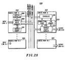
- the device for efficient switching of a plurality of received packets from a plurality of ingress ports to a plurality of egress ports may be described as a plurality of ingress ports (2002, 2004, %), each including an ingress memory (2010, %), an ingress queue manager (2008, %), and an arrival controller (2006, 7)and a plurality of egress ports (2012, 2014, 7) each including a connection table (2018, %), a tag memory (2020, %), a scheduler (2016, %), and an egress packet handler (2022, ).
- the ingress memory (2010, %) is used for storing a queue of packets for each connection of a plurality of connections.
- the ingress queue manager (2008, %) is coupled to the ingress memory (2010) and is used for receiving packets from an input link, storing the packets in ingress memory (2010, %), and for updating queue status information associated with the connection, where the IP has queue status information for each connection that goes through the IP and, upon receiving a connection identifier from a scheduler (2012, ...) of an egress port, retrieving a packet from the corresponding queue in ingress memory (2010, ...), updating the queue status information for the connection, and sending to the destination egress ports (2012, 2014, ...) the packet together with queue status information for determining, by the EP, whether packets remain in the packet queue that are unrequested by the EP.
- the arrival controller (2006, %) is coupled to the ingress queue manager (2008, %) and is utilized for, where the queue for a connection is empty when the packet arrives, sending an arrival tag containing at least a connection identifier to a destination egress port for the packet.
- the egress ports (2012, 2014, ...) are coupled to the ingress ports (2002, 2004, ).
- the connection table (2018, %) is used for storing, for each connection, at least an ACTIVE indicator, request status information, and queue status information.
- the tag memory (2020, %) is used for storing at most one tag per connection.
- the scheduler (2016, %) is coupled to the connection table (2018, %) and tag memory (2020, 7), for receiving arrival tags sent by ingress ports, storing the arrival tags in tag memory (2020, %), and setting the corresponding ACTIVE indicators True in the connection table (2018, ...); and for selecting a stored arrival tag in accordance with a predetermined scheme, and for each selected arrival tag, requesting the packet from the ingress port that sent the arrival tag, updating the request status information, determining, using at least one of: queue status information and the request status information, whether packets remain in the packet queue that are unrequested by the EP, and where the packet queue is empty, setting, by the EP, the ACTIVE indicator False in the connection table (2018, ).
- the egress packet handler (2022, %) is coupled to the connection table (2018, %) and tag memory (2020, 7) and is utilized for receiving the packet requested by the associated scheduler, storing the queue status information that accompanies the packet, and dispatching the packet on an output link, and where the ACTIVE indicator for the selected connection is False, determining, using at least one of: the queue status information and the request status information, whether packets remain in the packet queue that are unrequested by the EP, and where packets remain in the packet queue that are unrequested by the EP, generating an arrival tag corresponding to a next packet waiting, storing the arrival tag in tag memory (2020, ... ), and setting the ACTIVE indicator True in the connection table (2018, ... ).
- FIG. 21 is a block diagram showing the control flow and packet flow along an arrival pathway, a request pathway and a packet pathway in accordance with one embodiment of the present invention for connection-oriented networks.
- Packets arrive at an IP (2102) and are stored (a) in queues (2104) corresponding to individual connections.
- the IP sends an arrival tag (b) only if a packet arrives at an empty queue.
- the arrival tag contains a connection identifier code rather than the memory location of the stored packet.
- EPs (2106, ... ) store tags in a connection table (2108). Each EP selects tag and sends it to an IP over the Request Pathway (d).
- the IP uses the connection identifier code in the tag to locate the packet queue in which the packet is stored and dequeues the next packet.
- the IP labels the packet with the number of other packets waiting in the queue, then sends the packet on the Packet Pathway (e) to an output link via the EP.
Landscapes
- Engineering & Computer Science (AREA)
- Computer Networks & Wireless Communication (AREA)
- Signal Processing (AREA)
- Data Exchanges In Wide-Area Networks (AREA)
Claims (9)
- Ein Verfahren (1200, 1500, 1600, 1700, 1800) zum effizienten Schalten einer Vielzahl von empfangenen Paketen aus einer Vielzahl von Eingangsanschlüssen zu einer Vielzahl von Ausgangsanschlüssen, wobei die an den Eingangsanschlüssen ankommenden Pakete gespeichert werden und wobei das Schalten der Pakete zu einem Ziel-Ausgangsanschluss die folgenden Schritte umfasst:Speichern (1202) des Pakets bei Ankunft des Pakets in einem Paketspeicher;Senden (1204) einer Ankunftsmarkierung, die eine Ankunftsinformation einschließt, zu dem Ziel-Ausgangsanschluss, was anzeigt, dass mindestens ein Paket angekommen ist;Speichern (1208), von dem Ziel-Ausgangsanschluss, der Ankunftsmarkierung in einem Markierungsspeicher, der mit dem Ziel-Ausgangsanschluss assoziiert ist;Anfordern (1208), von jedem Ziel-Ausgangsanschluss, des/der gespeicherten Pakets/Pakete durch Auswählen einer Ankunftsmarkierung aus dem Markierungsspeicher gemäß einem vorbestimmten Schema und Senden der Ankunftsmarkierung zu dem Eingangsanschluss; undSenden (1210), von jedem Eingangsanschluss, von angeforderten Paketen mit einer Rate bis zu einer vorbestimmten Übertragungsrate des Eingangsanschlusses und Unterlassen des Sendens von angeforderten Paketen, die eine größere Übertragungsrate als die vorbestimmte Übertragungsrate erfordern, und bei den Fällen, bei denen das Senden der Pakete unterlassen wurde, erneutes Anfordern, von den Ziel-Ausgangsanschlüssen, der nicht gesendeten Pakete.
- Das Verfahren nach Anspruch 1, wobei die Vielzahl von Eingangsanschlüssen mit der Vielzahl von Ausgangsanschlüssen über eine ratenbeschränkte Schaltungsstruktur verbunden ist, die eine kleinere Rate als die Summe der maximalen Raten sämtlicher Ausgangsanschlüsse, aber einer größere als die Summe der mittleren Raten sämtlicher Ausgangsanschlüsse besitzt.
- Das Verfahren nach Anspruch 1, wobei für jede Verbindung über einen Ausgangsanschluss ein entsprechender ACTIVE-Indikator zu Beginn auf falsch gesetzt wird (1502) und wobei die an den Eingangsanschlüssen ankommenden Pakete in Paketwarteschlangen gespeichert werden (1504), wobei jede Warteschlange einer einzelnen Verbindung entspricht, wobei das Verfahren ferner durch die folgenden Schritte gekennzeichnet ist:A) Bestimmen (1506), von dem Eingangsanschluss, für jedes an dem Eingangsanschluss ankommende Paket, ob das Paket bei einer leeren Warteschlange angekommen ist, und bei den Fällen, bei denen das Paket bei einer leeren Warteschlange angekommen ist, Erzeugen, von dem Eingangsanschluss, einer Ankunftsmarkierung, die einen Verbindungsidentifizierungscode aufweist, Senden, von dem Eingangsanschluss, der Ankunftsmarkierung zu einem Ziel-Ausgangsanschluss für das Paket und Fortschreiten zu Schritt B und ansonsten zu Schritt C;B) Empfangen (1510), von dem Ausgangsanschluss, der Ankunftsmarkierung und Aufzeichnen einer Ankunft der Ankunftsmarkierung durch Setzen eines ACTIVE-Indikators auf wahr in einer Verbindungstabelle, die mit dem Ausgangsanschluss gekoppelt ist, wobei die Verbindungstabelle einen ACTIVE-Indikator für jede Verbindung aufweist, die den Ausgangsanschluss durchläuft;C) Auswählen (1512), von dem Ausgangsanschluss, aus den Verbindungen, die den ACTIVE-Indikator auf wahr in der Verbindungstabelle aufweisen, einer Verbindung gemäß einem vorbestimmten Schema, Setzen des ACTIVE-Indikators auf falsch für die ausgewählte Verbindung und Senden einer Anforderung, die mindestens die Verbindungsidentifizierung enthält, zurück zu dem Eingangsanschluss, der die Ankunftsmarkierung gesendet hat;D) Verwenden (1514), von dem Eingangsanschluss, nach Empfangen der Anforderung, der Verbindungsidentifizierung zur Lokalisierung der Paketwarteschlange und Entfernen eines nächsten Pakets aus der Warteschlange, Markieren des Pakets mit einem MORE-Indikator, der auf wahr ist, wenn mehrere Pakete in der Warteschlange verbleiben, und ansonsten auf falsch ist, und Senden des Pakets zu dem anfordernden Ausgangsanschluss; undE) Empfangen (1516), von dem Ausgangsanschluss, des angeforderten Pakets, und bei den Fällen, bei denen der MORE-Indikator in dem Paket auf wahr ist, Setzen, von dem Ausgangsanschluss, des ACTIVE-Indikators auf wahr in der Verbindungstabelle.
- Das Verfahren nach Anspruch 1, wobei für jede Verbindung über einen Eingangsanschluss ein assoziierte Modulo-Sequenzzählwert ARRIVSEQ vorhanden ist, wobei das Modulo von ARRIVSEQ S ist, "#" das Additions-Modulo S bezeichnet und "∥" einen Boole'schen OR-Operator bezeichnet; und wobei für jede Verbindung über einen Ausgangsanschluss eine Eingabe in einer Verbindungstabelle, die mit dem Ausgangsanschluss gekoppelt ist, vorhanden ist, die mindestens ein ACTIVE-Bit, ein MANY-Bit, einen REQSEQ-Wert und einen LASTSEQ-Wert enthält, und das ACTIVE-Bit für jede Verbindung zu Beginn auf falsch gesetzt wird; ferner durch die folgenden Schritte gekennzeichnet:A) Speichern (1604), von einem Eingangsanschluss, eines empfangenen Pakets in einer Paketwarteschlange in einem Speicher, wobei jede Warteschlange einer einzelnen Verbindung entspricht, und Aktualisieren des mit der Verbindung assoziierten ARRIVSEQ-Wertes auf ARRIVSEQ#1;B) Bestimmen (1606), von dem Eingangsanschluss, für jedes an dem Eingangsanschluss ankommende Paket, ob das Paket bei einer leeren Warteschlange angekommen ist, und bei den Fällen, bei denen das Paket bei einer leeren Warteschlange angekommen ist, Fortschreiten zu Schritt C und ansonsten zu Schritt E;C) Erzeugen (1608), von dem Eingangsanschluss, einer Ankunftsmarkierung, die einen Verbindungsidentifizierungscode aufweist, und bei den Fällen, bei denen sie ausgewählt ist, eine Zeitplanungsinformation einschließt, und Senden, von dem Eingangsanschluss, der Ankunftsmarkierung zu einem Ziel-Ausgangsanschluss für das Paket und Setzen des mit der Verbindung assoziierten ARRIVSEQ-Wertes auf einen vorausgewählten Wert SEQSTART#1;D) Empfangen (1610), von dem Ausgangsanschluss, der Ankunftsmarkierung und Aufzeichnen einer Ankunft der Ankunftsmarkierung durch Setzen des ACTIVE-Bit, Setzen von REQSEQ auf SEQSTART und Setzen von LASTSEQ auf SEQSTART#1 in der Verbindungstabelleneingabe für die Verbindung;E) Auswählen (1612), von dem Ausgangsanschluss, aus den Verbindungen, die ein gesetztes ACTIVE-Bit in der Verbindungstabelle aufweisen, einer Verbindung gemäß einem vorbestimmten Schema, Senden einer Anforderung, die mindestens die Verbindungsidentifizierung enthält, zurück zu dem Eingangsanschluss, der die Ankunftsmarkierung gesendet hat, Aktualisieren des REQSEQ-Wertes für die ausgewählte Verbindung auf REQSEQ#1 und Vergleichen des neuen Wertes von REQSEQ mit dem Wert von LASTSEQ für die ausgewählte Verbindung, und bei den Fällen, bei denen sie gleich sind und das MANY-Bit für die Verbindung auf falsch ist, Setzen des ACTIVE-Bit für die Verbindung auf falsch;F) Verwenden (1618), von dem Eingangsanschluss, nach Empfangen der Anforderung, der Verbindungsidentifizierung zur Lokalisierung der Paketwarteschlange und Entfernen eines nächsten Pakets aus der Warteschlange, Markieren des Pakets mit dem ARRIVSEQ-Wert für die Verbindung und Setzen, bei den Fällen, bei denen die Anzahl von Paketen in der Paketwarteschlange größer als oder gleich S ist, eines MANY-Bit in dem Paket auf wahr und ansonsten auf falsch; undG) Empfangen (1620), von dem Ausgangsanschluss, des angeforderten Pakets, Kopieren der ARRIVSEQ-Markierung in dem Paket zu dem LASTSEQ-Wert für die Verbindung in der Verbindungstabelle, Kopieren des MANY-Bit in dem Paket zu dem MANY-Bit für die Verbindung in der Verbindungstabelle, und Setzen, bei den Fällen, bei denen LASTSEQ # REQSEQ ∥ MANY = wahr für die Verbindung ist, des ACTIVE-Bit für die Verbindung auf wahr.
- Eine effiziente Paketschaltung (500, 600, 700, 1400, 1900, 2000) zum Schalten einer Vielzahl von empfangenen Paketen aus einer Vielzahl von Eingangsanschlüssen zu einer Vielzahl von Ausgangsanschlüssen, wobei die an den Eingangsanschlüssen ankommenden Pakete zum Schalten zu einem Ziel-Ausgangsanschluss gespeichert werden und wobei die Schaltung folgendes umfasst:A) eine Vielzahl von Ankunftssteuerungen (1906) mit einem Speicher zum Speichern jedes Pakets bei dessen Ankunft, wobei jeder Eingangsanschluss eine Ankunftssteuerung zum Senden einer Ankunftsmarkierung, die eine Ankunftsinformation einschließt, zu dem Ziel-Ausgangsanschluss besitzt, die anzeigt, das mindestens ein Paket angekommen ist; undB) eine Vielzahl von Zeitplanern (1916) mit einer Speicher, der mit dem Ziel-Ausgangsanschluss assoziiert ist, zum Speichern der Ankunftsmarkierung, wobei jeder Ausgangsanschluss einen Planer, der mit der Vielzahl von Ankunftssteuerungen gekoppelt ist, zum Anfordern, von jedem Ziel-Ausgangsanschluss, des/der gespeicherten Pakets/Pakete durch Auswählen einer Ankunftsmarkierung aus dem Markierungsspeicher gemäß einem vorbestimmten Schema und zum Senden der Ankunftsmarkierung zu dem Eingangsanschluss besitzt, worauf
der Eingangsanschluss angeforderte Pakete mit einer Rate bis zu einer vorbestimmten Übertragungsrate des Eingangsanschlusses sendet und das Senden von angeforderten Paketen, die eine größere Übertragungsrate als die vorbestimmte Übertragungsrate erfordern, unterlässt und
bei den Fällen, bei denen das Senden der Pakete unterlassen wurde, die Ziel-Ausgangsanschlüsse die nicht gesendeten Pakete erneut anfordern. - Die effiziente Paketschaltung nach Anspruch 5 zum Schalten eines empfangenen Pakets aus einem einer Vielzahl von Eingangsanschlüssen zu einem einer Vielzahl von Ausgangsanschlüssen, die folgendes umfasst:A) eine Vielzahl von Eingangsanschlüssen (702-704), die mit entsprechenden Paketspeichern zum Bestimmen eines Ziel-Ausgangsanschlusses für ein empfangenes Paket und zum Speichern des empfangenen Pakets verbunden sind;B) eine Vielzahl von Ausgangsanschlüssen (710-712), die mit entsprechenden Markierungsspeichern verbunden sind, wobei die Eingangsanschlüsse und die Ausgangsanschlüsse miteinander verbunden sind und wobei die effiziente Paketschaltung wie folgt arbeitet:B1) Bestimmen eines Ziel-Ausgangsanschlusses für ein empfangenes Paket und Speichern des empfangenen Pakets in einem Paketspeicher (706-708), der mit dem empfangenden Eingangsanschluss verbunden ist;B2) Senden, von dem empfangenden Eingangsanschluss, zu dem Ziel-Ausgangsanschluss einer Ankunftsmarkierung, die mindestens einen Speicherort (714-716) aufweist, und einer IP-Nummer, die anzeigt, wo das Paket gespeichert ist;B3) Empfangen, von dem Ziel-Ausgangsanschluss, der Ankunftsmarkierungen und Speichern der Ankunftsmarkierungen in einem Markierungsspeicher, der mit dem Ziel-Ausgangsanschluss verbunden ist;B4) Auswählen, von dem Ziel-Ausgangsanschluss, einer gespeicherten Ankunftsmarkierung gemäß einem vorbestimmten Schema und Senden der ausgewählten gespeicherten Ankunftsmarkierung zurück zu dem Eingangsanschluss, der die Ankunftsmarkierung gesendet hat, um eine Übertragung des mit der Ankunftsmarkierung assoziierten empfangenen Pakets anzufordern;B5) Empfangen, von dem Eingangsanschluss, der ausgewählten gespeicherten Ankunftsmarkierung, Abrufen des mit der Ankunftsmarkierung assoziierten empfangenen Pakets und Senden des mit der Ankunftsmarkierung assoziierten empfangenen Pakets zu dem Ziel-Ausgangsanschluss; undB6) Empfangen, von dem Ziel-Ausgangsanschluss, des mit der Ankunftsmarkierung assoziierten empfangenen Pakets und Absenden des empfangenen Pakets von dem Ziel-Ausgangsanschluss; wobei bei den Fällen, bei denen ein Eingangsanschluss eine Vielzahl von Ankunftsmarkierungen, die Anforderungen für Pakete repräsentieren, von einer Vielzahl von Ausgangsanschlüssen empfängt, sendet der Eingangsanschluss angeforderte Pakete gemäß einer vorbestimmten Anforderungsrate und verweigert Anforderungen, die die vorbestimmte Anforderungsrate überschreiten, und wobei bei den Fällen, bei denen die Anforderung eines Ausgangsanschlusses verweigert wurde, der Ausgangsanschluss die Anforderung wiederholt.
- Die effiziente Paketschaltung nach Anspruch 6, wobei die Ankunftsmarkierung Information zur Organisierung von Markierungen, die wartende Pakete repräsentieren, in mehrere Warteschlangen einschließt, die mindestens eines aus:A) verschiedene Verbindungen;B) Prioritäten; undC) Dienstgüten;
für die Zeitplanung des Pakets in dem Ziel-Ausgangsanschluss repräsentieren. - Die effiziente Paketschaltung nach Anspruch 6, wobei die Paketschaltung in Zellzyklen mittels eines zentral erzeugten CELLCLK-Signals synchronisiert ist, das von einer Zellzeitgeberleitung geliefert wird, die mit sämtlichen Eingangs- und Ausgangsanschlüssen verbunden ist, wobei ein Zellzyklus eine Zeitspanne ist, während der nur ein Paket an jedem Eingangsanschluss ankommt, jeder Eingangsanschluss nur eine Ankunftsmarkierung pro Zellzyklus erzeugt, jeder Ausgangsanschluss nur eine Anforderung pro Zellzyklus erzeugt und jeder Ausgangsanschluss maximal ein Paket pro Zellzyklus auf einer Ausgangsleitung sendet.
- Die effiziente Paketschaltung nach Anspruch 5 zum Schalten einer Vielzahl von empfangenen Paketen aus einer Vielzahl von Eingangsanschlüssen zu einer Vielzahl von Ausgangsanschlüssen, wobei:die Vielzahl von Eingangsanschlüssen (1902-1904) jeweils folgendes umfasst:A) einen Eingangsspeicher (1910) zum Speichern einer Warteschlange von Paketen für jede Verbindung aus einer Vielzahl von Verbindungen;B) einen Eingangswarteschlangenverwalter (1908), der mit dem Eingangsspeicher gekoppelt ist, zum Empfangen von Paketen aus einer Eingangsleitung, Speichern der Pakete in einem Eingangsspeicher und zum Aktualisieren der Warteschlangenstatusinformation, die mit der Verbindung assoziiert ist, wobei der Eingangsanschluss Warteschlangenstatusinformation für jede Verbindung aufweist, die den Eingangsanschluss durchläuft, und, nach Empfangen einer Verbindungsidentifizierung von einem Zeitplaner eines Ausgangsanschlusses, Abrufen eines Pakets aus der entsprechenden Warteschlange in dem Eingangsanschlussspeicher, Aktualisieren der Warteschlangenstatusinformation für die Verbindung und Senden des Pakets zu den Ziel-Ausgangsanschlüssen zusammen mit der Warteschlangenstatusinformation zum Bestimmen, von dem Ausgangsanschluss, ob Pakete in der Paketwarteschlange verbleiben, die von dem Ausgangsanschluss nicht angefordert wurden; undC) die Ankunftssteuerung (1906), die mit dem Eingangswarteschlangenverwalter gekoppelt ist, zum Senden, bei den Fällen, bei denen die Warteschlange für eine Verbindung leer ist, wenn das Paket ankommt, einer Ankunftsmarkierung, die mindestens eine Verbindungsidentifizierung enthält, zu einem Ziel-Ausgangsanschluss für das Paket;
und die Vielzahl von Ausgangsanschlüssen (1912-1914), wobei die Ausgangsanschlüsse mit den Eingangsanschlüssen gekoppelt sind und jeder Ausgangsanschluss folgendes umfasst:D) eine Verbindungstabelle (1918) zum Speichern, für jede Verbindung, mindestens eines ACTIVE-Indikators, einer Anforderungsstatusinformation und einer Warteschlangenstatusinformation;E) den Zeitplaner (1916), der mit der Verbindungstabelle gekoppelt ist, zum Empfangen von Ankunftsmarkierungen, die von Eingangsanschlüssen gesendet wurden, und Setzen der entsprechenden ACTIVE-Indikatoren auf wahr in der Verbindungstabelle; und zum Auswählen von Verbindungen, die den gesetzten ACTIVE-Indikator aufweisen, gemäß einem vorbestimmten Schema und, für jede ausgewählte Verbindung, Anfordern des Pakets von dem Eingangsanschluss, der die entsprechende Ankunftsmarkierung gesendet hat, Aktualisieren der Anforderungsstatusinformation, Bestimmen, unter Verwendung von mindestens einem aus: Warteschlangenstatusinformation und der Anforderungsstatusinformation, ob Pakete in der Paketwarteschlange verbleiben, die von dem Ausgangsanschluss nicht angefordert wurden, und bei den Fällen, bei denen die Paketwarteschlange leer ist, Setzen, von dem Ausgangsanschluss, des ACTIVE-Indikators auf falsch in der Verbindungstabelle; undF) ein Ausgangspaketsteuerungsprogramm (1920), das mit der Verbindungstabelle gekoppelt ist, zum Empfangen des von dem assoziierten Zeitplaner angeforderten Pakets, Speichern der Warteschlangenstatusinformation, die das Paket begleitet, und Absenden des Pakets auf einer Ausgangsleitung, und bei den Fällen, bei denen der ACTIVE-Indikator für die ausgewählte Verbindung auf falsch ist, Bestimmen, unter Verwendung von mindestens einem aus: der Warteschlangenstatusinformation und der Anforderungsstatusinformation, ob Pakete in der Paketwarteschlange verbleiben, die von dem Ausgangsanschluss nicht angefordert wurden, und bei den Fällen, bei denen Pakete in der Paketwarteschlange verbleiben, die von dem Ausgangsanschluss nicht angefordert wurden, Setzen des ACTIVE-Indikators auf wahr in der Verbindungstabelle.
Applications Claiming Priority (3)
| Application Number | Priority Date | Filing Date | Title |
|---|---|---|---|
| US616024 | 1990-11-20 | ||
| US08/616,024 US5790545A (en) | 1996-03-14 | 1996-03-14 | Efficient output-request packet switch and method |
| PCT/US1997/003920 WO1997034394A1 (en) | 1996-03-14 | 1997-03-13 | Efficient output-request packet switch and method |
Publications (3)
| Publication Number | Publication Date |
|---|---|
| EP0886939A1 EP0886939A1 (de) | 1998-12-30 |
| EP0886939A4 EP0886939A4 (de) | 2000-04-19 |
| EP0886939B1 true EP0886939B1 (de) | 2009-05-13 |
Family
ID=24467752
Family Applications (1)
| Application Number | Title | Priority Date | Filing Date |
|---|---|---|---|
| EP97915038A Expired - Lifetime EP0886939B1 (de) | 1996-03-14 | 1997-03-13 | Effiziente paketvermittlung mit ausgangsanforderung und verfahren |
Country Status (9)
| Country | Link |
|---|---|
| US (1) | US5790545A (de) |
| EP (1) | EP0886939B1 (de) |
| JP (1) | JP3415628B2 (de) |
| KR (1) | KR100334922B1 (de) |
| CN (1) | CN1152532C (de) |
| AU (1) | AU2208597A (de) |
| CA (1) | CA2247447C (de) |
| DE (1) | DE69739399D1 (de) |
| WO (1) | WO1997034394A1 (de) |
Families Citing this family (96)
| Publication number | Priority date | Publication date | Assignee | Title |
|---|---|---|---|---|
| US6016307A (en) | 1996-10-31 | 2000-01-18 | Connect One, Inc. | Multi-protocol telecommunications routing optimization |
| US6473404B1 (en) | 1998-11-24 | 2002-10-29 | Connect One, Inc. | Multi-protocol telecommunications routing optimization |
| US6295299B1 (en) * | 1997-08-29 | 2001-09-25 | Extreme Networks, Inc. | Data path architecture for a LAN switch |
| US7100020B1 (en) * | 1998-05-08 | 2006-08-29 | Freescale Semiconductor, Inc. | Digital communications processor |
| US6185635B1 (en) * | 1998-05-30 | 2001-02-06 | Alcatel Networks Corporation | Method and circuit for transporting data based on the content of ingress data words and egress data words |
| US6145010A (en) * | 1998-07-14 | 2000-11-07 | 3Com Corporation | Method and apparatus for bandwidth control in an over subscribed computer network switch |
| US6147969A (en) * | 1998-10-14 | 2000-11-14 | Lucent Technologies Inc. | Flow control method for ABR service in an asynchronous transfer mode network |
| US6408001B1 (en) | 1998-10-21 | 2002-06-18 | Lucent Technologies Inc. | Method for determining label assignments for a router |
| US6735190B1 (en) | 1998-10-21 | 2004-05-11 | Lucent Technologies Inc. | Packet transport method device utilizing header removal fields |
| US6597690B1 (en) | 1999-01-22 | 2003-07-22 | Intel Corporation | Method and apparatus employing associative memories to implement limited switching |
| US6570887B2 (en) * | 1999-01-22 | 2003-05-27 | Intel Corporation | Method and apparatus employing associative memories to implement message passing |
| US6711163B1 (en) * | 1999-03-05 | 2004-03-23 | Alcatel | Data communication system with distributed multicasting |
| US6747971B1 (en) | 1999-04-20 | 2004-06-08 | Cisco Technology, Inc. | Crosspoint switch with independent schedulers |
| US6625160B1 (en) * | 1999-07-02 | 2003-09-23 | Cisco Technology, Inc. | Minimum bandwidth guarantee for cross-point buffer switch |
| US6633576B1 (en) | 1999-11-04 | 2003-10-14 | William Melaragni | Apparatus and method for interleaved packet storage |
| US6731644B1 (en) * | 2000-02-14 | 2004-05-04 | Cisco Technology, Inc. | Flexible DMA engine for packet header modification |
| US6721316B1 (en) | 2000-02-14 | 2004-04-13 | Cisco Technology, Inc. | Flexible engine and data structure for packet header processing |
| US6813243B1 (en) | 2000-02-14 | 2004-11-02 | Cisco Technology, Inc. | High-speed hardware implementation of red congestion control algorithm |
| US6977930B1 (en) | 2000-02-14 | 2005-12-20 | Cisco Technology, Inc. | Pipelined packet switching and queuing architecture |
| US6778546B1 (en) | 2000-02-14 | 2004-08-17 | Cisco Technology, Inc. | High-speed hardware implementation of MDRR algorithm over a large number of queues |
| US6813274B1 (en) | 2000-03-21 | 2004-11-02 | Cisco Technology, Inc. | Network switch and method for data switching using a crossbar switch fabric with output port groups operating concurrently and independently |
| US7065580B1 (en) * | 2000-03-31 | 2006-06-20 | Sun Microsystems, Inc. | Method and apparatus for a pipelined network |
| US7020161B1 (en) | 2000-03-31 | 2006-03-28 | Sun Microsystems, Inc. | Prescheduling arbitrated resources |
| US6975626B1 (en) | 2000-03-31 | 2005-12-13 | Sun Microsystems, Inc. | Switched network for low latency communication |
| US7061929B1 (en) | 2000-03-31 | 2006-06-13 | Sun Microsystems, Inc. | Data network with independent transmission channels |
| US6829651B1 (en) * | 2000-04-11 | 2004-12-07 | International Business Machines Corporation | Local MAC address learning in layer 2 frame forwarding |
| US7236489B1 (en) | 2000-04-27 | 2007-06-26 | Mosaid Technologies, Inc. | Port packet queuing |
| US6816489B1 (en) | 2000-10-05 | 2004-11-09 | Cisco Technology, Inc. | Efficient method for packet switching on asynchronous transfer mode switch based platforms |
| US7042891B2 (en) * | 2001-01-04 | 2006-05-09 | Nishan Systems, Inc. | Dynamic selection of lowest latency path in a network switch |
| RU2257678C2 (ru) * | 2001-01-31 | 2005-07-27 | ТЕЛДИКС ГмбХ | Модульный масштабируемый коммутатор и способ распределения кадров в сети быстрого ethernet |
| WO2002062023A1 (en) * | 2001-01-31 | 2002-08-08 | Teldix Gmbh | Modular and scalable switch and method for the distribution of fast ethernet data frames |
| WO2002091672A2 (en) * | 2001-05-07 | 2002-11-14 | Vitesse Semiconductor Corporation | A system and a method for processing data packets or frames |
| US7295563B2 (en) * | 2001-10-01 | 2007-11-13 | Advanced Micro Devices, Inc. | Method and apparatus for routing packets that have ordering requirements |
| US7221678B1 (en) | 2001-10-01 | 2007-05-22 | Advanced Micro Devices, Inc. | Method and apparatus for routing packets |
| US6973036B2 (en) * | 2001-11-01 | 2005-12-06 | International Business Machines Corporation | QoS scheduler and method for implementing peak service distance using next peak service time violated indication |
| US7046676B2 (en) * | 2001-11-01 | 2006-05-16 | International Business Machines Corporation | QoS scheduler and method for implementing quality of service with cached status array |
| US7280474B2 (en) * | 2001-11-01 | 2007-10-09 | International Business Machines Corporation | Weighted fair queue having adjustable scaling factor |
| US6982986B2 (en) * | 2001-11-01 | 2006-01-03 | International Business Machines Corporation | QoS scheduler and method for implementing quality of service anticipating the end of a chain of flows |
| US7317683B2 (en) * | 2001-11-01 | 2008-01-08 | International Business Machines Corporation | Weighted fair queue serving plural output ports |
| US7103051B2 (en) * | 2001-11-01 | 2006-09-05 | International Business Machines Corporation | QoS scheduler and method for implementing quality of service with aging time stamps |
| US7310345B2 (en) * | 2001-11-01 | 2007-12-18 | International Business Machines Corporation | Empty indicators for weighted fair queues |
| CA2365688A1 (en) * | 2001-12-19 | 2003-06-19 | Alcatel Canada Inc. | System and method for providing gaps at ingress to a network element |
| CN1175633C (zh) * | 2001-12-26 | 2004-11-10 | Lg电子株式会社 | 基于atm的mpls-ler系统和建立该系统的连接的方法 |
| US7352741B2 (en) * | 2002-02-21 | 2008-04-01 | Sun Microsystems, Inc. | Method and apparatus for speculative arbitration |
| US7680043B2 (en) | 2002-03-20 | 2010-03-16 | International Business Machines Corporation | Network processor having fast flow queue disable process |
| US7257124B2 (en) * | 2002-03-20 | 2007-08-14 | International Business Machines Corporation | Method and apparatus for improving the fairness of new attaches to a weighted fair queue in a quality of service (QoS) scheduler |
| US6956861B2 (en) * | 2002-04-16 | 2005-10-18 | Interactics Holdings, Llc | Controlled shared memory smart switch system |
| US7397768B1 (en) | 2002-09-11 | 2008-07-08 | Qlogic, Corporation | Zone management in a multi-module fibre channel switch |
| US7525910B2 (en) | 2003-07-16 | 2009-04-28 | Qlogic, Corporation | Method and system for non-disruptive data capture in networks |
| US7471635B2 (en) | 2003-07-16 | 2008-12-30 | Qlogic, Corporation | Method and apparatus for test pattern generation |
| US7620059B2 (en) | 2003-07-16 | 2009-11-17 | Qlogic, Corporation | Method and apparatus for accelerating receive-modify-send frames in a fibre channel network |
| US7453802B2 (en) | 2003-07-16 | 2008-11-18 | Qlogic, Corporation | Method and apparatus for detecting and removing orphaned primitives in a fibre channel network |
| US7646767B2 (en) | 2003-07-21 | 2010-01-12 | Qlogic, Corporation | Method and system for programmable data dependant network routing |
| US7447224B2 (en) | 2003-07-21 | 2008-11-04 | Qlogic, Corporation | Method and system for routing fibre channel frames |
| US7466700B2 (en) | 2003-07-21 | 2008-12-16 | Qlogic, Corporation | LUN based hard zoning in fibre channel switches |
| US7792115B2 (en) | 2003-07-21 | 2010-09-07 | Qlogic, Corporation | Method and system for routing and filtering network data packets in fibre channel systems |
| US7522522B2 (en) | 2003-07-21 | 2009-04-21 | Qlogic, Corporation | Method and system for reducing latency and congestion in fibre channel switches |
| US7558281B2 (en) | 2003-07-21 | 2009-07-07 | Qlogic, Corporation | Method and system for configuring fibre channel ports |
| US7406092B2 (en) | 2003-07-21 | 2008-07-29 | Qlogic, Corporation | Programmable pseudo virtual lanes for fibre channel systems |
| US7430175B2 (en) | 2003-07-21 | 2008-09-30 | Qlogic, Corporation | Method and system for managing traffic in fibre channel systems |
| US7630384B2 (en) | 2003-07-21 | 2009-12-08 | Qlogic, Corporation | Method and system for distributing credit in fibre channel systems |
| US7583597B2 (en) * | 2003-07-21 | 2009-09-01 | Qlogic Corporation | Method and system for improving bandwidth and reducing idles in fibre channel switches |
| US7684401B2 (en) | 2003-07-21 | 2010-03-23 | Qlogic, Corporation | Method and system for using extended fabric features with fibre channel switch elements |
| US7573909B2 (en) | 2003-07-21 | 2009-08-11 | Qlogic, Corporation | Method and system for programmable data dependant network routing |
| US7512067B2 (en) | 2003-07-21 | 2009-03-31 | Qlogic, Corporation | Method and system for congestion control based on optimum bandwidth allocation in a fibre channel switch |
| US7580354B2 (en) | 2003-07-21 | 2009-08-25 | Qlogic, Corporation | Multi-speed cut through operation in fibre channel switches |
| US7477655B2 (en) | 2003-07-21 | 2009-01-13 | Qlogic, Corporation | Method and system for power control of fibre channel switches |
| US7525983B2 (en) | 2003-07-21 | 2009-04-28 | Qlogic, Corporation | Method and system for selecting virtual lanes in fibre channel switches |
| US7522529B2 (en) | 2003-07-21 | 2009-04-21 | Qlogic, Corporation | Method and system for detecting congestion and over subscription in a fibre channel network |
| US7894348B2 (en) | 2003-07-21 | 2011-02-22 | Qlogic, Corporation | Method and system for congestion control in a fibre channel switch |
| US7420982B2 (en) * | 2003-07-21 | 2008-09-02 | Qlogic, Corporation | Method and system for keeping a fibre channel arbitrated loop open during frame gaps |
| US7543142B2 (en) | 2003-12-19 | 2009-06-02 | Intel Corporation | Method and apparatus for performing an authentication after cipher operation in a network processor |
| US7512945B2 (en) | 2003-12-29 | 2009-03-31 | Intel Corporation | Method and apparatus for scheduling the processing of commands for execution by cryptographic algorithm cores in a programmable network processor |
| US20050149744A1 (en) * | 2003-12-29 | 2005-07-07 | Intel Corporation | Network processor having cryptographic processing including an authentication buffer |
| US7529924B2 (en) * | 2003-12-30 | 2009-05-05 | Intel Corporation | Method and apparatus for aligning ciphered data |
| US7480293B2 (en) | 2004-02-05 | 2009-01-20 | Qlogic, Corporation | Method and system for preventing deadlock in fibre channel fabrics using frame priorities |
| US7564789B2 (en) | 2004-02-05 | 2009-07-21 | Qlogic, Corporation | Method and system for reducing deadlock in fibre channel fabrics using virtual lanes |
| US7340167B2 (en) * | 2004-04-23 | 2008-03-04 | Qlogic, Corporation | Fibre channel transparent switch for mixed switch fabrics |
| US7930377B2 (en) | 2004-04-23 | 2011-04-19 | Qlogic, Corporation | Method and system for using boot servers in networks |
| US20060171386A1 (en) * | 2004-09-01 | 2006-08-03 | Interactic Holdings, Llc | Means and apparatus for a scaleable congestion free switching system with intelligent control III |
| CN1747440B (zh) * | 2004-09-08 | 2012-05-02 | 华为技术有限公司 | 一种实现信元重排序的芯片 |
| US7593997B2 (en) | 2004-10-01 | 2009-09-22 | Qlogic, Corporation | Method and system for LUN remapping in fibre channel networks |
| US8295299B2 (en) | 2004-10-01 | 2012-10-23 | Qlogic, Corporation | High speed fibre channel switch element |
| US7281093B1 (en) * | 2004-12-21 | 2007-10-09 | Xilinx, Inc. | Memory apparatus for a message processing system and method of providing same |
| US7519058B2 (en) | 2005-01-18 | 2009-04-14 | Qlogic, Corporation | Address translation in fibre channel switches |
| US7548560B1 (en) | 2006-02-27 | 2009-06-16 | Qlogic, Corporation | Method and system for checking frame-length in fibre channel frames |
| EP1860033B1 (de) * | 2006-05-26 | 2011-01-12 | MTC - Macchine Trasformazione Carta Srl | Vorrichtung zur Umhüllung von Bögenstapeln |
| US7923341B2 (en) * | 2007-08-13 | 2011-04-12 | United Solar Ovonic Llc | Higher selectivity, method for passivating short circuit current paths in semiconductor devices |
| JP2009177256A (ja) * | 2008-01-21 | 2009-08-06 | Fujitsu Ltd | パケットスイッチ装置およびパケットスイッチ方法 |
| JP5143203B2 (ja) * | 2010-09-24 | 2013-02-13 | 株式会社東芝 | メモリシステム |
| EP2668753B1 (de) * | 2011-01-28 | 2017-10-04 | Napatech A/S | Vorrichtung und verfahren zum empfangen und weiterleiten von datenpaketen |
| US8694994B1 (en) | 2011-09-07 | 2014-04-08 | Amazon Technologies, Inc. | Optimization of packet processing by delaying a processor from entering an idle state |
| US20140379780A1 (en) * | 2013-06-25 | 2014-12-25 | Sap Ag | Determining a support package status |
| US9894013B2 (en) * | 2015-02-03 | 2018-02-13 | Avago Technologies General Ip (Singapore) Pte. Ltd. | Early queueing network device |
| RU175722U1 (ru) * | 2017-03-01 | 2017-12-15 | Общество с ограниченной ответственностью "КЬЮТЭК" | Ethernet коммутатор |
| WO2019214801A1 (en) * | 2018-05-07 | 2019-11-14 | Huawei Technologies Co., Ltd. | Memory device for a high bandwidth high capacity switch |
Citations (1)
| Publication number | Priority date | Publication date | Assignee | Title |
|---|---|---|---|---|
| EP0624015A2 (de) * | 1993-05-07 | 1994-11-09 | Roke Manor Research Limited | Verbesserungen in ATM-Nachrichtensystemen |
Family Cites Families (4)
| Publication number | Priority date | Publication date | Assignee | Title |
|---|---|---|---|---|
| US4623996A (en) * | 1984-10-18 | 1986-11-18 | Mcmillen Robert J | Packet switched multiple queue NXM switch node and processing method |
| JPS61214694A (ja) * | 1985-03-18 | 1986-09-24 | インタ−ナショナル ビジネス マシ−ンズ コ−ポレ−ション | データ伝送のスイッチング装置 |
| FR2623954B1 (fr) * | 1987-11-27 | 1993-11-19 | Alcatel Cit | Element de commutation de donnees transmises par multiplexage temporel asynchrone |
| US5001706A (en) * | 1989-06-23 | 1991-03-19 | At&T Bell Laboratories | Packet cross connect switch system including improved throughput |
-
1996
- 1996-03-14 US US08/616,024 patent/US5790545A/en not_active Expired - Lifetime
-
1997
- 1997-03-13 CN CNB971929556A patent/CN1152532C/zh not_active Expired - Lifetime
- 1997-03-13 CA CA002247447A patent/CA2247447C/en not_active Expired - Lifetime
- 1997-03-13 KR KR1019980707224A patent/KR100334922B1/ko not_active Expired - Lifetime
- 1997-03-13 WO PCT/US1997/003920 patent/WO1997034394A1/en not_active Ceased
- 1997-03-13 JP JP53281797A patent/JP3415628B2/ja not_active Expired - Lifetime
- 1997-03-13 EP EP97915038A patent/EP0886939B1/de not_active Expired - Lifetime
- 1997-03-13 AU AU22085/97A patent/AU2208597A/en not_active Abandoned
- 1997-03-13 DE DE69739399T patent/DE69739399D1/de not_active Expired - Lifetime
Patent Citations (1)
| Publication number | Priority date | Publication date | Assignee | Title |
|---|---|---|---|---|
| EP0624015A2 (de) * | 1993-05-07 | 1994-11-09 | Roke Manor Research Limited | Verbesserungen in ATM-Nachrichtensystemen |
Also Published As
| Publication number | Publication date |
|---|---|
| KR19990087752A (ko) | 1999-12-27 |
| JP2000506701A (ja) | 2000-05-30 |
| US5790545A (en) | 1998-08-04 |
| EP0886939A4 (de) | 2000-04-19 |
| AU2208597A (en) | 1997-10-01 |
| CA2247447A1 (en) | 1997-09-18 |
| CN1214168A (zh) | 1999-04-14 |
| EP0886939A1 (de) | 1998-12-30 |
| WO1997034394A1 (en) | 1997-09-18 |
| HK1019529A1 (en) | 2000-02-11 |
| KR100334922B1 (ko) | 2002-06-20 |
| CA2247447C (en) | 2003-10-21 |
| DE69739399D1 (de) | 2009-06-25 |
| JP3415628B2 (ja) | 2003-06-09 |
| CN1152532C (zh) | 2004-06-02 |
Similar Documents
| Publication | Publication Date | Title |
|---|---|---|
| EP0886939B1 (de) | Effiziente paketvermittlung mit ausgangsanforderung und verfahren | |
| AU693084B2 (en) | Controlled access ATM switch | |
| US6473428B1 (en) | Multi-threaded, multi-cast switch | |
| US6791992B1 (en) | Earliest-deadline-first queuing cell switching architecture and method | |
| US5850395A (en) | Asynchronous transfer mode based service consolidation switch | |
| US7773602B2 (en) | CAM based system and method for re-sequencing data packets | |
| US7050440B2 (en) | Method and structure for variable-length frame support in a shared memory switch | |
| US6768717B1 (en) | Apparatus and method for traffic shaping in a network switch | |
| EP0603916A2 (de) | Paketvermittlungssystem unter Verwendung des Belegstatus der Ausgangspuffer | |
| US20060221945A1 (en) | Method and apparatus for shared multi-bank memory in a packet switching system | |
| CN1859263B (zh) | 信元重排序方法、使用该方法的信元处理方法及装置 | |
| GB2365665A (en) | Switching arrangement for data packets | |
| US6574232B1 (en) | Crossbar switch utilizing broadcast buffer and associated broadcast buffer management unit | |
| US5742597A (en) | Method and device for multipoint switching and arbitration in output-request packet switch | |
| US6445706B1 (en) | Method and device in telecommunications system | |
| US7269158B2 (en) | Method of operating a crossbar switch | |
| US7379470B2 (en) | Combined and data compressed FIFO based arbitration for a non-blocking switch | |
| JPH07183897A (ja) | 空間分割交換マトリクスの入力へ接続するための入力待ち行列システム | |
| ES2235366T3 (es) | Procedimiento y sistema de circuitos para transmitir unidades de mensajes en flujos de mensajes de distinta prioridad. | |
| CA2227655A1 (en) | The single-queue switch | |
| AU724624B2 (en) | Controlled access ATM switch | |
| EP1209865B1 (de) | Verfahren und Struktur zur Unterstützung von Rahmen variabler Länge in einer Vermittlungsanlage mit gemeisamem Speicher | |
| WO2000074321A1 (en) | Apparatus and method for traffic shaping in a network switch | |
| WO1997004568A1 (en) | Asynchronous transfer mode based service consolidation switch | |
| HK1019529B (en) | Efficient output-request packet switch and method |
Legal Events
| Date | Code | Title | Description |
|---|---|---|---|
| PUAI | Public reference made under article 153(3) epc to a published international application that has entered the european phase |
Free format text: ORIGINAL CODE: 0009012 |
|
| 17P | Request for examination filed |
Effective date: 19981014 |
|
| AK | Designated contracting states |
Kind code of ref document: A1 Designated state(s): DE FR GB |
|
| A4 | Supplementary search report drawn up and despatched |
Effective date: 20000306 |
|
| AK | Designated contracting states |
Kind code of ref document: A4 Designated state(s): DE FR GB |
|
| 17Q | First examination report despatched |
Effective date: 20050908 |
|
| GRAP | Despatch of communication of intention to grant a patent |
Free format text: ORIGINAL CODE: EPIDOSNIGR1 |
|
| GRAS | Grant fee paid |
Free format text: ORIGINAL CODE: EPIDOSNIGR3 |
|
| GRAA | (expected) grant |
Free format text: ORIGINAL CODE: 0009210 |
|
| AK | Designated contracting states |
Kind code of ref document: B1 Designated state(s): DE FR GB |
|
| REG | Reference to a national code |
Ref country code: GB Ref legal event code: FG4D |
|
| REF | Corresponds to: |
Ref document number: 69739399 Country of ref document: DE Date of ref document: 20090625 Kind code of ref document: P |
|
| PLBE | No opposition filed within time limit |
Free format text: ORIGINAL CODE: 0009261 |
|
| STAA | Information on the status of an ep patent application or granted ep patent |
Free format text: STATUS: NO OPPOSITION FILED WITHIN TIME LIMIT |
|
| 26N | No opposition filed |
Effective date: 20100216 |
|
| REG | Reference to a national code |
Ref country code: GB Ref legal event code: 732E Free format text: REGISTERED BETWEEN 20110127 AND 20110202 |
|
| REG | Reference to a national code |
Ref country code: DE Ref legal event code: R081 Ref document number: 69739399 Country of ref document: DE Owner name: MOTOROLA MOBILITY, INC. ( N.D. GES. D. STAATES, US Free format text: FORMER OWNER: MOTOROLA, INC., SCHAUMBURG, ILL., US Effective date: 20110324 Ref country code: DE Ref legal event code: R081 Ref document number: 69739399 Country of ref document: DE Owner name: MOTOROLA MOBILITY, INC. ( N.D. GES. D. STAATES, US Free format text: FORMER OWNER: MOTOROLA, INC., SCHAUMBURG, US Effective date: 20110324 |
|
| REG | Reference to a national code |
Ref country code: FR Ref legal event code: TP Owner name: MOTOROLA MOBILITY, INC., US Effective date: 20110912 |
|
| REG | Reference to a national code |
Ref country code: DE Ref legal event code: R082 Ref document number: 69739399 Country of ref document: DE Representative=s name: KASTEL PATENTANWAELTE PARTG MBB, DE Ref country code: DE Ref legal event code: R082 Ref document number: 69739399 Country of ref document: DE Representative=s name: KASTEL PATENTANWAELTE, DE |
|
| REG | Reference to a national code |
Ref country code: FR Ref legal event code: PLFP Year of fee payment: 20 |
|
| PGFP | Annual fee paid to national office [announced via postgrant information from national office to epo] |
Ref country code: GB Payment date: 20160329 Year of fee payment: 20 Ref country code: FR Payment date: 20160328 Year of fee payment: 20 |
|
| PGFP | Annual fee paid to national office [announced via postgrant information from national office to epo] |
Ref country code: DE Payment date: 20160331 Year of fee payment: 20 |
|
| REG | Reference to a national code |
Ref country code: DE Ref legal event code: R071 Ref document number: 69739399 Country of ref document: DE |
|
| REG | Reference to a national code |
Ref country code: GB Ref legal event code: PE20 Expiry date: 20170312 |
|
| PG25 | Lapsed in a contracting state [announced via postgrant information from national office to epo] |
Ref country code: GB Free format text: LAPSE BECAUSE OF EXPIRATION OF PROTECTION Effective date: 20170312 |
|
| REG | Reference to a national code |
Ref country code: GB Ref legal event code: 732E Free format text: REGISTERED BETWEEN 20170831 AND 20170906 |
|
| P01 | Opt-out of the competence of the unified patent court (upc) registered |
Effective date: 20230520 |