EP0887066B1 - Automatischer Hochgeschwindigkeits-Zählapparat für Pillen - Google Patents
Automatischer Hochgeschwindigkeits-Zählapparat für Pillen Download PDFInfo
- Publication number
- EP0887066B1 EP0887066B1 EP97310260A EP97310260A EP0887066B1 EP 0887066 B1 EP0887066 B1 EP 0887066B1 EP 97310260 A EP97310260 A EP 97310260A EP 97310260 A EP97310260 A EP 97310260A EP 0887066 B1 EP0887066 B1 EP 0887066B1
- Authority
- EP
- European Patent Office
- Prior art keywords
- pill
- pills
- speed
- feeder
- lower portion
- Prior art date
- Legal status (The legal status is an assumption and is not a legal conclusion. Google has not performed a legal analysis and makes no representation as to the accuracy of the status listed.)
- Expired - Lifetime
Links
Images
Classifications
-
- G—PHYSICS
- G06—COMPUTING OR CALCULATING; COUNTING
- G06M—COUNTING MECHANISMS; COUNTING OF OBJECTS NOT OTHERWISE PROVIDED FOR
- G06M11/00—Counting of objects distributed at random, e.g. on a surface
-
- B—PERFORMING OPERATIONS; TRANSPORTING
- B65—CONVEYING; PACKING; STORING; HANDLING THIN OR FILAMENTARY MATERIAL
- B65B—MACHINES, APPARATUS OR DEVICES FOR, OR METHODS OF, PACKAGING ARTICLES OR MATERIALS; UNPACKING
- B65B35/00—Supplying, feeding, arranging or orientating articles to be packaged
- B65B35/06—Separating single articles from loose masses of articles
- B65B35/08—Separating single articles from loose masses of articles using pocketed conveyors
-
- B—PERFORMING OPERATIONS; TRANSPORTING
- B65—CONVEYING; PACKING; STORING; HANDLING THIN OR FILAMENTARY MATERIAL
- B65B—MACHINES, APPARATUS OR DEVICES FOR, OR METHODS OF, PACKAGING ARTICLES OR MATERIALS; UNPACKING
- B65B57/00—Automatic control, checking, warning, or safety devices
- B65B57/20—Applications of counting devices for controlling the feed of articles
-
- G—PHYSICS
- G07—CHECKING-DEVICES
- G07F—COIN-FREED OR LIKE APPARATUS
- G07F11/00—Coin-freed apparatus for dispensing, or the like, discrete articles
- G07F11/02—Coin-freed apparatus for dispensing, or the like, discrete articles from non-movable magazines
- G07F11/04—Coin-freed apparatus for dispensing, or the like, discrete articles from non-movable magazines in which magazines the articles are stored one vertically above the other
- G07F11/16—Delivery means
- G07F11/24—Rotary or oscillatory members
-
- G—PHYSICS
- G07—CHECKING-DEVICES
- G07F—COIN-FREED OR LIKE APPARATUS
- G07F11/00—Coin-freed apparatus for dispensing, or the like, discrete articles
- G07F11/62—Coin-freed apparatus for dispensing, or the like, discrete articles in which the articles are stored in compartments in fixed receptacles
-
- G—PHYSICS
- G07—CHECKING-DEVICES
- G07F—COIN-FREED OR LIKE APPARATUS
- G07F17/00—Coin-freed apparatus for hiring articles; Coin-freed facilities or services
- G07F17/0092—Coin-freed apparatus for hiring articles; Coin-freed facilities or services for assembling and dispensing of pharmaceutical articles
Definitions
- the present invention relates to an automatic high-speed pill counting apparatus for general purposes to prevent the pills from being soiled or broken and to count the pills quickly and accurately.
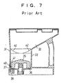
- reference numeral 31 designates a casing having a rectangular section
- numeral 42 designates corners having a round shape.
- the pills are rubbed by the inner wall of the cylindrical portion so that the inner wall becomes dirty. If the numerous pills are agitated in the cylindrical portion, powder is produced to soil the pills themselves. Moreover, the powder agglomerates, when it is discharged, to raise a problem in the safety of medicine.
- the pill exit has such a restricted opening as to catch the pills thereby to damage or break them.
- this system is not suitable for the high speed so that it can be employed exclusively at a low speed.
- an automatic high-speed pill counting apparatus comprising a base plate, a cylindrical hopper on said base plate, a pill exit in the base plate and a centre hole in the base plate, a rotational separate feeder rotatably mounted in a lower portion of the cylindrical pill hopper and removably mounted on a shaft borne in the centre hole in the base plate, the feeder including an upper portion and a lower portion having an outer circumference the external diameter of which is greater than that of the upper portion and is approximately equal to the internal diameter of the lower portion of the cylindrical hopper, characterised by a plurality of through holes provided in and around the outer circumference of the lower portion of the feeder each adapted to accommodate therein a plurality of stacked pills, a ring-shaped slit being formed in the outer circumference of the lower portion to divide each through hole into an upper hole and a lower hole, the lower hole diverging downwardly and outwardly and being capable of accommodating a single pill, a pill separating plate mounted on the cylindrical hopper above the pill exit
- the through holes in the lower portion of the feeder each include a notch formed in the outer circumference of the lower portion, a thin sheet being fixed on the outer circumference of said lower portion to cover the notches.
- a groove is formed in the lower portion of the inner wall of said cylindrical pill hopper and has a diameter approximately equal to the external diameter of the lower portion of the feeder.
- the automatic high-speed pill counting apparatus may further comprise first control means for controlling the speed of rotation of the drive motor such that the drive motor is driven at a first speed to rotate said feeder at a first speed thereby to discharge pills from the pill exit and to count them by the pill passage counting sensor, such that, when the number of pills discharged reaches approximately a set number, the drive motor is driven at a lower speed to rotate the feeder at a lower speed and to count the pills by said pill passage counting sensor, and such that, when the number of pills reaches a set number, the drive of the drive motor is interrupted.
- a plurality of cylindrical pill hoppers may be connected to the lower end of one mass hopper, and the automatic high-speed pill counting apparatus may further comprise second control means for controlling the individual drive motors such that each drive motor is driven at a first speed, thereby to discharge pills from the individual pill exits and to add together the numbers counted by each individual pill passage counting sensor, such that, when the number of pills is approximately equal to a set number, only one drive motor is driven at a lower speed to rotate one feeder at a lower speed and count the pills by the associated pill passage counting sensor, the drives of the remaining drive motors being interrupted, and such that, when the number of pills reaches a set number, the drives of all the drive motors are interrupted.
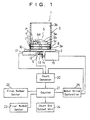
- Fig. 1 is a block diagram of a mechanism and a system of the automatic high-seed pill counting apparatus according to the invention. As shown in Fig. 1, the automatic high-speed pill counting apparatus 1 has a base plate 2, on which is erected a cylindrical pill hopper 3.
- a multistage rotational separative feeder 5 having a circular top plan shape through a shaft 6 extending through the base plate 2. This multistage rotational separative feeder 5 is removably fitted on the shaft 6.
- the multistage rotational separative feeder 5 is composed, sequentially downward in the following recited order, of: an upper agitating portion 5a having a plurality of steps for agitating pills P; a diametrically smaller portion 5b having such a predetermined gap between itself and the inner circumference 3b of the pill hopper 3 as to allow substantially one pill to pass therethrough; and a diametrically larger portion 5c fitted loosely in the diametrically larger groove 3a of the pill hopper 3.
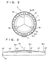
- Fig. 2 is a top plan view of the multistage rotational separative feeder
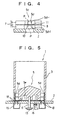
- Fig. 3 is an expanded side view of the upper agitating portion and the diametrically smaller portion of the multistage rotational separative feeder.
- the upper agitating portion 5a has a conical side elevation, as shown in Figs. 1 to 3, and is divided into three sectors, as viewed in a top plan view. Each sector is sloped from the rotationally front side to the rotationally rear side thereby to form a step 5a-1 at each side.
- the upper agitating portion 5a is enabled to agitate a number of pills P by its conical shape and its steps 5a-1, 5a-1 and 5a-1 thereby to guide them to its circumferential portion.
- the pills as having fallen down between the diametrically smaller portion 5b of the multistage rotational separative feeder 5 and the inner circumference 3b of the pill hopper 3, will further fall down into holes 5d having a U-shaped top plan view, which are formed at a predetermined pitch to extend vertically through the outer circumference of the diametrically larger portion 5c and which are opened at their outer sides.
- holes 5d having a U-shaped top plan view, which are formed at a predetermined pitch to extend vertically through the outer circumference of the diametrically larger portion 5c and which are opened at their outer sides.
- On the outer circumference of the diametrically larger portion 5c there is fixed a metal sheet 7 so that the pills P having fallen down into the holes 5d are brought into abutment against the metal sheet 7 in accordance with the rotation of the multistage rotational separative feeder 5.
- the pills P are prevented from popping out of the diametrically larger portion 5c and abutting against the diametrically larger groove 3a of the pill hopper 3 so that neither the diametrically larger groove 3a is soiled with dirt, nor the pills P are rubbed and broken.
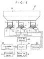
- the diametrically larger portion 5c of the multistage rotational separative feeder 5 has a ring-shaped groove or slit 8 in the substantially vertical center of the outer circumference.
- Fig. 4 is an enlarged explanatory side elevation of the diametrically larger portion of the multistage rotational separative feeder.
- the metal sheet 7 and the individual U-shaped holes 5d of the diametrically larger portion 5c are vertically halved by the slit 8 so that the metal sheet 7 is divided into an upper metallic sheet 7a and a lower metallic sheet 7b whereas the holes 5d are divided into upper holes 5d-1 and lower holes 5d-2.
- the lower holes 5d-2 of the holes 5d are so diverged downward that their inside pills may be easily separated from those in the upper holes 5d-1 and may easily fall down without any bite.
- a pill exit 10 in the base plate 2 , moreover, there is formed a pill exit 10, as shown in Fig. 1.
- This pill exit 10 can be aligned with one arbitrary hole 5d of the multistage rotational separative feeder 5 so that it can be aligned with all the holes 5d as the multistage rotational separative feeder 5 is rotated.
- a pill separating plate 11 having an L-shaped side elevation, which has an inwardly projected tip fitted loosely in the slit 8 of the diametrically larger portion 5c.
- This pill separating plate 11 prevents the pills P having fallen down into the upper holes 5d-1 of the holes 5d of the diametrically larger portion 5c from further falling down into the lower holes 5d-2.
- the shaft 6 is equipped with a position signal detecting sensor 12 for detecting the rotational position of the shaft 6, i.e., the rotational position of the multistage rotational separative feeder 5.
- a position signal detecting sensor 12 for detecting the rotational position of the shaft 6, i.e., the rotational position of the multistage rotational separative feeder 5.
- One gear 13 of a bevel gear train is fixed on the leading end of the shaft 6, and the other gear 14 meshing with the former gear 13 is fixed on the spindle of a rotational separative feeder drive motor 15 which is a pulse motor.
- a pill passage counting sensor 17 for counting the number of pills having passed.
- a ring-shaped groove 5e which is in communication with an air inlet 16 formed in the base plate 2.
- the holes 5d of the multistage rotational separative feeder 5 there are circumferentially formed at a predetermined pitch a plurality of holes 18 and 18 which have a suitably radial spacing from each other.
- a ring-shaped duct 19 is formed below the numerous holes 18 in the base plate 2.
- arrows in Fig. 5 indicate the flows of air.
- reference numeral 20 designates a count detector for receiving and processing the signals coming from the position signal detecting sensor 12, the pill passage counting sensor 17 and a later-described motor drive controller 25;
- numeral 21 designates a counter for counting the number of pills on the basis of a detection signal coming from the count detector 20;
- numeral 22 designates a first (high-speed counting) number setter;
- numeral 23 designates a final number setter;
- numeral 24 designates a count end output unit;
- the numeral 25 designates the motor drive controller for controlling the drive of the rotational separative feeder drive motor 15.
- the signal of the motor drive controller 25, the rotational position, as detected by the position signal detecting sensor 12, of the multistage rotational separative feeder 5, and the number detected by the pill passage counting sensor 17 are inputted to and processed by the count detector 20.
- the pills P having fallen into the pill exit 10 and counted by the pill passage counting sensor 17 are guided through the not-shown hopper and pouring mechanism to fall into a packaging mechanism so that they are accumulated in packages.
- the number from the count detector 20 is inputted to and processed by the counter 21. If this counted number is within the value set by the first number setter 22, the signal is outputted to the motor drive controller 25 and the latter drives the multistage rotational separative feeder 5 at a high speed.
- This high-speed drive of the multistage rotational separative feeder 5 is continued till the counted number from the count detector 20 reaches the first number (e.g., 96) set by the first number setter 22.
- the motor drive controller 25 drives the multistage rotational separative feeder 5 at a low speed.
- This low-speed drive of the multistage rotational separative feeder 5 is continued till the counted number from the count detector 20 reaches the final number (e.g., 100) set by the final number setter 23 .
- the output of the counter 21 is fed to the count end output unit 24.
- the motor drive controller 25 interrupts the drive of the multistage rotational separative feeder 5, and the counted value of the count detector is cleared.
- the output signal from the count end output unit 24 is inputted to the not-shown packaging mechanism so that the packages can be interchanged.
- the counting is instantly interrupted because even if the signal from the motor drive controller 25 is inputted to the count detector 20 the position signal from the position signal detecting sensor 12 is not changed.
- the multistage rotational separative feeder 5 is removed from the shaft 6, and another multistage rotational separative feeder is fitted on the shaft and the mounting position of the pill separating plate 11 may be vertically adjusted, if necessary.
- the multistage rotational separative feeder 5 is driven at a high speed till the first number is reached, and is driven at a low speed when the first number is reached, so that the pills can be counted at a high speed but without fail.
- the metal sheet 7 is fixed on the outer circumference of the diametrically larger portion 5c of the multistage rotational separative feeder 5 so that the pills neither pop out of the diametrically larger portion 5c nor abut against the diametrically larger groove 3a of the pill hopper 3 in accordance with the rotation of the multistage rotational separative feeder 5.
- the diametrically larger groove 3a is soiled with dirt, nor the pills are rubbed to become dirty.
- the lower holes 5d-2 of the holes 5d are so diverged downward that the pills may easily fall down without any bite.
- the pills can be reliably counted by the position signal detecting sensor 12 and the pill passage counting sensor 17.
- a multi-row automatic high-speed pill counting apparatus 27 is constructed like the foregoing first embodiment, excepting that it is equipped with a single mass hopper 28, that the multiple rows of the aforementioned pill hoppers 3, 3 and 3 are connected to the lower end of the mass hopper 28, that the count detector 20 is replaced by a count add detector 29, and that the motor drive controller 25 for controlling the drive of the single rotational separative feeder drive motor 15 is replaced by a motor drive controller 30 for controlling the drives of a plurality of rotational separative feeder drive motors 15.
- the numerous pills P are poured into the upper mouth of the mass hopper 28 so that the multiple rows of pill hoppers 3 , 3 and 3 are charged with the pills P.
- the individual rotational separative feeder drive motors 15 are driven under this state, the individual multistage rotational separative feeders 5 are rotated so that the pills P drop from the individual pill exits 10 and are detected and counted by the individual pill passage counting sensors 17. These counted numbers are inputted to and processed by the count add detector 29. Simultaneously with this, the rotational positions, as detected by the individual position signal detecting sensors 12, of the multistage rotational separative feeders 5, and the signals of the motor drive controller 30 are inputted to and processed by the count add detector 29.
- the multistage rotational separative feeders 5, 5 and 5 on are driven at a high speed till the total number from the count add detector 29 reaches the first number (e.g., 96) set by the first number setter 22.
- the motor drive controller 30 drives only one multistage rotational separative feeder 5 at a low speed but interrupts the drives of the remaining two multistage rotational separative feeders 5 and 5.
- the one multistage rotational separative feeder 5 is driven at a low speed till the counted number from the count add detector 29 reaches the final number (e.g., 100) set by the final number setter 23. When this final number is reached, the output of the counter 21 is fed to the count end output unit 24. At the same time, the motor drive controller 30 interrupts the drive of the one multistage rotational separative feeder 5, and the counted value of the count add detector 29 is cleared.
- the final number e.g. 100
- the pills P having fallen into the pill exits 10, 10 and 10 and counted by the pill passage counting sensors 17, 17 and 17 are guided through the not-shown hoppers and pouring mechanisms to fall into packaging mechanisms so that they are accumulated in packages.
- the output signal from the count end output unit 24 is inputted to the not-shown packaging mechanisms so that the packages can be interchanged.
- a plurality of multistage rotational separative feeders are driven at a high speed till the first number is reached, and only one multistage rotational separative feeder is driven at a low speed when the first number is reached, so that the pills can be counted at a higher speed and without fail.
- two pills are vertically accommodated in each hole 5d of the diametrically larger portion 5c of the multistage rotational separative feeder.
- the invention should not be limited thereto but can naturally be so modified that three, four or more pills are vertically accommodated.
- three multi-row pill hoppers are connected to one mass hopper.
- the invention should not be limited thereto, but two, four, five or more pill hoppers may be combined.
- the metal sheet 7 is fixed on the outer circumference of the diametrically larger portion 5c of the multistage rotational separative feeder.
- the invention should not be limited to the metal sheet but may adopt a sheet of another material. Alternatively, a number of through holes may naturally be formed in the outer circumference of the multistage rotational separative feeder.
- the rotational separative feeder drive motor is exemplified by the pulse motor.
- the invention should not be limited thereto but may adopt another type of motor.
- the multistage rotational separative feeder is driven at a high speed and is driven at a low speed when a set number is approached, so that the pills can be counted fast and reliably.
- the pills are prevented from popping out to the outside of the lower diametrically larger portion and from abutting against the inner circumference of the pill hopper as the multistage rotational separative feeder rotates, so that neither the inner circumference of the pill hopper is soiled with dirt nor the pills are rubbed to become dirty.
- the multi-row cylindrical pill hoppers are connected to the lower end of the single mass hopper, and the individual multistage rotational separative feeders in the multi-row cylindrical pill hoppers are driven at a high speed.
- the set number is approached, only one multistage rotational separative feeder is driven at a low speed whereas the drive of the remaining multistage rotational separative feeders is interrupted.
- the set number is reached, all the drive motors are inactivated. As a result, the pills can be counted at a higher speed and without fail.
Landscapes
- Physics & Mathematics (AREA)
- General Physics & Mathematics (AREA)
- Engineering & Computer Science (AREA)
- Mechanical Engineering (AREA)
- Theoretical Computer Science (AREA)
- Medical Preparation Storing Or Oral Administration Devices (AREA)
- Basic Packing Technique (AREA)
Claims (5)
- Automatische Hochgeschwindigkeitspillenzählvorrichtung (1), umfassend eine Basisplatte (2), einen zylindrischen Trichter (3) auf der Basisplatte, einen Pillenausgang (10) in der Basisplatte (2) und ein Mittelloch in der Basisplatte (2), eine sich drehende getrennte Zufuhr (5), die drehbar in einem unteren Abschnitt des zylindrischen Pillentrichters montiert und abnehmbar auf einer Welle montiert ist, die im Mittelloch in der Basisplatte (2) gelagert ist, wobei die Zufuhr einen oberen Abschnitt (5a) sowie einen unteren Abschnitt (5c) umfasst, der einen Außenumfang aufweist, dessen Außendurchmesser größer ist als jener des oberen Abschnitts (5b) und etwa gleich dem Innendurchmesser des unteren Abschnitts des zylindrischen Trichters ist, gekennzeichnet durch eine Vielzahl von Durchgangslöchern (5d), die in und um den Außenumfang des unteren Abschnitts (5c) der Zufuhr (5) vorgesehen sind und ausgebildet sind, um darin eine Vielzahl übereinander angeordnete Pillen aufzunehmen, wobei ein ringförmiger Schlitz (8) im Außenumfang des unteren Abschnitts (5c) ausgebildet ist, um jedes Durchgangsloch (5d) in ein oberes Loch (5d-1) und ein unteres Loch (5d-2) zu unterteilen, wobei das untere Loch (5d-2) nach unten und nach außen divergiert und in der Lage ist, eine einzelne Pille aufzunehmen, eine Pillentrennplatte (11), die auf dem zylindrischen Trichter (3) oberhalb des Pillenausgangs (10) montiert ist und eine nach innen ragende Spitze aufweist, die lose in den Schlitz (8) passt, einen Antriebsmotor (15) zum Antreiben der Welle, wodurch jedes Durchgangsloch (5d) der Reihe nach mit dem Pillenausgang (10) ausgerichtet wird, und einen Pillendurchgangszählsensor (17), der unterhalb des Pillenausgangs (10) angeordnet ist.
- Automatische Hochgeschwindigkeitspillenzählvorrichtung (1) nach Anspruch 1, worin die Durchgangslöcher (5d) im unteren Abschnitt der Zufuhr (5) jeweils eine Kerbe umfassen, die im Außenumfang des unteren Abschnitts (5c) ausgebildet ist, wobei eine dünne Folie am Außenumfang des unteren Abschnitts befestigt ist, um die Kerben abzudecken.
- Automatische Hochgeschwindigkeitspillenzählvorrichtung (1) nach Anspruch 1 oder 2, worin eine Rille (3a) im unteren Abschnitt der Innenwand des zylindrischen Pillentrichters (3) ausgebildet ist und einen Durchmesser aufweist, der in etwa gleich dem Außendurchmesser des unteren Abschnitts (5c) der Zufuhr (5) ist.
- Automatische Hochgeschwindigkeitspillenzählvorrichtung (1) nach einem der Ansprüche 1 bis 3, die weiters umfasst:ein erstes Steuerungsmittel zur Steuerung der Rotationsgeschwindigkeit des Antriebsmotors (15), so dass der Antriebsmotor (15) mit einer ersten Geschwindigkeit angetrieben wird, um die Zufuhr (5) mit einer ersten Geschwindigkeit zu drehen, um dadurch Pillen aus dem Pillenausgang (10) abzugeben und sie mit dem Pillendurchgangszählsensor (17) zu zählen, so dass, wenn die Anzahl an abgegebenen Pillen in etwa eine festgelegte Zahl erreicht, der Antriebsmotor (15) mit einer geringeren Geschwindigkeit angetrieben wird, um die Zufuhr (5) mit einer geringeren Geschwindigkeit zu drehen und die Pillen mit dem Pillendurchgangszählsensor (17) zu zählen, und so dass, wenn die Anzahl an Pillen eine festgelegte Zahl erreicht, der Antrieb des Antriebsmotors unterbrochen wird.
- Automatische Hochgeschwindigkeitspillenzählvorrichtung (1) nach einem der Ansprüche 1 bis 4, worin eine Vielzahl zylindrischer Pillentrichter (3) mit dem unteren Ende eines Massetrichters verbunden sind, wobei die Vorrichtung weiters ein zweites Steuerungsmittel zur Steuerung der einzelnen Antriebsmotoren (15) umfasst, so dass jeder Antriebsmotor (15) mit einer ersten Geschwindigkeit angetrieben wird, wodurch Pillen aus den einzelnen Pillenausgängen (10) abgegeben werden und die von jedem einzelnen Pillendurchgangszählsensor (17) gezählten Zahlen zusammengezählt werden, so dass, wenn die Anzahl an Pillen etwa gleich einer festgelegten Zahl ist, nur ein Antriebsmotor (15) mit einer geringeren Geschwindigkeit angetrieben wird, um eine Zufuhr (5) mit einer geringeren Geschwindigkeit zu drehen und die Pillen mit dem zugeordneten Pillendurchgangszählsensor (17) zu zählen, wobei die Antriebe der verbleibenden Antriebsmotore (15) unterbrochen werden, und so dass, wenn die Anzahl an Pillen eine festgelegte Zahl erreicht, die Antriebe aller Antriebsmotoren (15) unterbrochen werden.
Applications Claiming Priority (3)
| Application Number | Priority Date | Filing Date | Title |
|---|---|---|---|
| JP17043897 | 1997-06-26 | ||
| JP170438/97 | 1997-06-26 | ||
| JP17043897A JP3211078B2 (ja) | 1997-06-26 | 1997-06-26 | 錠剤の自動高速計数装置 |
Publications (3)
| Publication Number | Publication Date |
|---|---|
| EP0887066A2 EP0887066A2 (de) | 1998-12-30 |
| EP0887066A3 EP0887066A3 (de) | 1999-09-22 |
| EP0887066B1 true EP0887066B1 (de) | 2003-11-26 |
Family
ID=15904928
Family Applications (1)
| Application Number | Title | Priority Date | Filing Date |
|---|---|---|---|
| EP97310260A Expired - Lifetime EP0887066B1 (de) | 1997-06-26 | 1997-12-18 | Automatischer Hochgeschwindigkeits-Zählapparat für Pillen |
Country Status (4)
| Country | Link |
|---|---|
| US (1) | US6253953B1 (de) |
| EP (1) | EP0887066B1 (de) |
| JP (1) | JP3211078B2 (de) |
| DE (1) | DE69726413D1 (de) |
Cited By (1)
| Publication number | Priority date | Publication date | Assignee | Title |
|---|---|---|---|---|
| WO2015139545A1 (zh) * | 2014-03-21 | 2015-09-24 | 达尔嘉(广州)标识设备有限公司 | 一种物品定量分堆及计数的方法及装置 |
Families Citing this family (29)
| Publication number | Priority date | Publication date | Assignee | Title |
|---|---|---|---|---|
| SE516650C2 (sv) * | 1997-11-04 | 2002-02-05 | Sensidos Ab | Förfarande och anordning för dosering och dispensering av läkemedel |
| US6371715B1 (en) * | 2000-07-03 | 2002-04-16 | Advanced Micro Devices, Inc. | Automated tube to tube transfer of a predetermined number of IC packages for various types of IC packages |
| JP2002153541A (ja) * | 2000-11-20 | 2002-05-28 | Tosho Inc | 薬剤フィーダ |
| AU2003287821A1 (en) * | 2002-12-09 | 2004-06-30 | Script Innovations Inc. | Universal pill counting device |
| US7080755B2 (en) * | 2004-09-13 | 2006-07-25 | Michael Handfield | Smart tray for dispensing medicaments |
| JP4348741B2 (ja) * | 2005-06-27 | 2009-10-21 | 日本電気株式会社 | 光学的情報記録媒体及び光学的情報再生装置 |
| US8386275B2 (en) | 2009-02-10 | 2013-02-26 | Timothy Chambers | Automatic pill dispensing device and method of use thereof |
| JP5363936B2 (ja) * | 2009-10-14 | 2013-12-11 | 靜甲株式会社 | フィーダ |
| US20110231010A1 (en) * | 2010-03-20 | 2011-09-22 | Richard Panetta | Pill counting and control system for a pill transport apparatus |
| US8417375B2 (en) | 2010-05-13 | 2013-04-09 | Data Detection Technologies Ltd. | Counting machine for discrete items |
| EP2649980A4 (de) * | 2010-12-09 | 2017-09-20 | Yuyama Mfg. Co., Ltd. | Arzneimittelspender und arzneimittelzähler |
| DE102011001129A1 (de) * | 2011-03-07 | 2012-09-13 | Gerresheimer item GmbH | Dosiervorrichtung zur Dosierung von Mikrotabletten und Globuli |
| GB2486939B (en) | 2011-12-01 | 2012-11-21 | Data Detection Technologies Ltd | Method and apparatus for dispensing items |
| US20160251094A1 (en) * | 2013-10-09 | 2016-09-01 | Takazono Technology Incorporated | Medicine Filling Apparatus |
| SG11201602739WA (en) * | 2013-10-09 | 2016-05-30 | Takazono Technology Inc | Medicine filling apparatus |
| EP3056184A4 (de) * | 2013-10-09 | 2017-06-28 | Takazono Technology Incorporated | Medizinfüllvorrichtung |
| US10421566B2 (en) | 2014-07-03 | 2019-09-24 | Carefusion Germany 326 Gmbh | Storage container for automated dispensing of individual medicament portions |
| US9828168B2 (en) * | 2014-07-03 | 2017-11-28 | Carefusion Germany 326 Gmbh | Storage container for automated dispensing of individual medicament portions |
| CN104590917B (zh) * | 2015-01-26 | 2019-07-09 | 深圳国控医疗有限公司 | 自动供药机 |
| US11735304B2 (en) | 2017-09-26 | 2023-08-22 | Mckesson Corporation | Robotic dispensary system and methods |
| CN109907986A (zh) * | 2019-04-18 | 2019-06-21 | 常州市第二人民医院 | 一种口服药丸计数装置 |
| US11410764B1 (en) | 2019-11-15 | 2022-08-09 | Express Scripts Strategic Development, Inc. | Smart medication dispenser |
| JP7486887B2 (ja) * | 2020-01-08 | 2024-05-20 | 三光機械株式会社 | 充填物供給装置 |
| CN111773106B (zh) * | 2020-06-29 | 2023-04-07 | 杭州电子科技大学 | 自动喂药机 |
| CN112793813A (zh) * | 2021-02-04 | 2021-05-14 | 陈敏芝 | 一种自动配药系统 |
| US12036185B2 (en) | 2021-07-19 | 2024-07-16 | Optum, Inc. | System and method to count pills |
| CN115158803B (zh) * | 2022-07-18 | 2024-03-26 | 江苏仅一联合智造有限公司 | 一种插动式高度计量数粒机构 |
| US12612243B2 (en) | 2022-07-29 | 2026-04-28 | Express Scripts Strategic Development, Inc. | Hopper for a pharmaceutical counter |
| CN115318669A (zh) * | 2022-08-24 | 2022-11-11 | 安徽宏信药业发展有限公司 | 一种药丸分选装置 |
Family Cites Families (5)
| Publication number | Priority date | Publication date | Assignee | Title |
|---|---|---|---|---|
| US3368713A (en) * | 1968-02-13 | Kerney J Hurst | Article counting device | |
| JPS5866186A (ja) * | 1981-10-15 | 1983-04-20 | Tokyo Shokai:Kk | 衝撃センサを具備した錠剤フイ−ダ− |
| JPS6034620A (ja) | 1983-07-29 | 1985-02-22 | Kurabo Ind Ltd | 梳綿機制御装置 |
| AU602680B2 (en) * | 1986-04-28 | 1990-10-25 | Kerney J. Hurst | Article counting device |
| US6161721A (en) * | 1999-02-23 | 2000-12-19 | Scriptpro Llc | Medicament dispensing cell with dual platens |
-
1997
- 1997-06-26 JP JP17043897A patent/JP3211078B2/ja not_active Expired - Lifetime
- 1997-12-18 EP EP97310260A patent/EP0887066B1/de not_active Expired - Lifetime
- 1997-12-18 DE DE69726413T patent/DE69726413D1/de not_active Expired - Lifetime
-
1998
- 1998-01-06 US US09/003,501 patent/US6253953B1/en not_active Expired - Fee Related
Cited By (1)
| Publication number | Priority date | Publication date | Assignee | Title |
|---|---|---|---|---|
| WO2015139545A1 (zh) * | 2014-03-21 | 2015-09-24 | 达尔嘉(广州)标识设备有限公司 | 一种物品定量分堆及计数的方法及装置 |
Also Published As
| Publication number | Publication date |
|---|---|
| EP0887066A3 (de) | 1999-09-22 |
| DE69726413D1 (de) | 2004-01-08 |
| US6253953B1 (en) | 2001-07-03 |
| JPH119664A (ja) | 1999-01-19 |
| JP3211078B2 (ja) | 2001-09-25 |
| EP0887066A2 (de) | 1998-12-30 |
Similar Documents
| Publication | Publication Date | Title |
|---|---|---|
| EP0887066B1 (de) | Automatischer Hochgeschwindigkeits-Zählapparat für Pillen | |
| EP0204405B1 (de) | Münzenausgabevorrichtung | |
| US11155378B2 (en) | Gating system for accumulating items and related filling machine and methods | |
| US7281361B2 (en) | Method of article portioning | |
| US6343711B1 (en) | Medicament dispensing cell | |
| US20090044495A1 (en) | Packaging Apparatus for Handling Pills and Associated Method | |
| US5927546A (en) | Tablet feeder | |
| US20070289660A1 (en) | Vacuum Apparatus and Methods for Handling Pills | |
| US6471093B1 (en) | Tablet feeder | |
| US5176290A (en) | Coin operated vending machine | |
| US20090094947A1 (en) | Packaging Apparatus for Handling Pills and Associated Method | |
| JP3626059B2 (ja) | 錠剤の自動高速計数装置 | |
| US3326223A (en) | Coin counting and controlling apparatus | |
| US2292864A (en) | Apparatus for feeding articles | |
| JP5877010B2 (ja) | 硬貨繰出装置及び硬貨処理装置 | |
| KR200307228Y1 (ko) | 환약선별장치 | |
| JPH09328110A (ja) | 物品計数投入機 | |
| JPS6351927B2 (de) | ||
| CN106986061B (zh) | 一种糖果包装机的理糖装置 | |
| TW202139961A (zh) | 錠劑送出裝置、具有錠劑送出裝置的藥劑分包機、錠劑分類裝置 | |
| CN219524483U (zh) | 一种药剂金属异物检测装置 | |
| WO2011033761A1 (ja) | 切り出し計数装置 | |
| JP2000163554A (ja) | 防塵機構および高速計数装置 | |
| JPH084058Y2 (ja) | パチンコ機用景品球放出装置 | |
| WO2021246422A1 (ja) | 錠剤放出装置、錠剤放出装置を有する薬剤分包機 |
Legal Events
| Date | Code | Title | Description |
|---|---|---|---|
| PUAI | Public reference made under article 153(3) epc to a published international application that has entered the european phase |
Free format text: ORIGINAL CODE: 0009012 |
|
| AK | Designated contracting states |
Kind code of ref document: A2 Designated state(s): CH DE FR GB IT LI |
|
| AX | Request for extension of the european patent |
Free format text: AL;LT;LV;MK;RO;SI |
|
| PUAL | Search report despatched |
Free format text: ORIGINAL CODE: 0009013 |
|
| AK | Designated contracting states |
Kind code of ref document: A3 Designated state(s): AT BE CH DE DK ES FI FR GB GR IE IT LI LU MC NL PT SE |
|
| AX | Request for extension of the european patent |
Free format text: AL;LT;LV;MK;RO;SI |
|
| 17P | Request for examination filed |
Effective date: 20000112 |
|
| AKX | Designation fees paid |
Free format text: CH DE FR GB IT LI |
|
| 17Q | First examination report despatched |
Effective date: 20020621 |
|
| GRAH | Despatch of communication of intention to grant a patent |
Free format text: ORIGINAL CODE: EPIDOS IGRA |
|
| GRAS | Grant fee paid |
Free format text: ORIGINAL CODE: EPIDOSNIGR3 |
|
| GRAA | (expected) grant |
Free format text: ORIGINAL CODE: 0009210 |
|
| AK | Designated contracting states |
Kind code of ref document: B1 Designated state(s): CH DE FR GB IT LI |
|
| PG25 | Lapsed in a contracting state [announced via postgrant information from national office to epo] |
Ref country code: LI Free format text: LAPSE BECAUSE OF FAILURE TO SUBMIT A TRANSLATION OF THE DESCRIPTION OR TO PAY THE FEE WITHIN THE PRESCRIBED TIME-LIMIT Effective date: 20031126 Ref country code: IT Free format text: LAPSE BECAUSE OF FAILURE TO SUBMIT A TRANSLATION OF THE DESCRIPTION OR TO PAY THE FEE WITHIN THE PRESCRIBED TIME-LIMIT;WARNING: LAPSES OF ITALIAN PATENTS WITH EFFECTIVE DATE BEFORE 2007 MAY HAVE OCCURRED AT ANY TIME BEFORE 2007. THE CORRECT EFFECTIVE DATE MAY BE DIFFERENT FROM THE ONE RECORDED. Effective date: 20031126 Ref country code: FR Free format text: LAPSE BECAUSE OF FAILURE TO SUBMIT A TRANSLATION OF THE DESCRIPTION OR TO PAY THE FEE WITHIN THE PRESCRIBED TIME-LIMIT Effective date: 20031126 Ref country code: CH Free format text: LAPSE BECAUSE OF FAILURE TO SUBMIT A TRANSLATION OF THE DESCRIPTION OR TO PAY THE FEE WITHIN THE PRESCRIBED TIME-LIMIT Effective date: 20031126 |
|
| REG | Reference to a national code |
Ref country code: GB Ref legal event code: FG4D |
|
| REG | Reference to a national code |
Ref country code: CH Ref legal event code: EP |
|
| REF | Corresponds to: |
Ref document number: 69726413 Country of ref document: DE Date of ref document: 20040108 Kind code of ref document: P |
|
| PG25 | Lapsed in a contracting state [announced via postgrant information from national office to epo] |
Ref country code: DE Free format text: LAPSE BECAUSE OF FAILURE TO SUBMIT A TRANSLATION OF THE DESCRIPTION OR TO PAY THE FEE WITHIN THE PRESCRIBED TIME-LIMIT Effective date: 20040227 |
|
| REG | Reference to a national code |
Ref country code: CH Ref legal event code: PL |
|
| PLBE | No opposition filed within time limit |
Free format text: ORIGINAL CODE: 0009261 |
|
| STAA | Information on the status of an ep patent application or granted ep patent |
Free format text: STATUS: NO OPPOSITION FILED WITHIN TIME LIMIT |
|
| 26N | No opposition filed |
Effective date: 20040827 |
|
| EN | Fr: translation not filed | ||
| PGFP | Annual fee paid to national office [announced via postgrant information from national office to epo] |
Ref country code: GB Payment date: 20051220 Year of fee payment: 9 |
|
| GBPC | Gb: european patent ceased through non-payment of renewal fee |
Effective date: 20061218 |
|
| PG25 | Lapsed in a contracting state [announced via postgrant information from national office to epo] |
Ref country code: GB Free format text: LAPSE BECAUSE OF NON-PAYMENT OF DUE FEES Effective date: 20061218 |