EP0887217B1 - Windstop-Einrichtung - Google Patents
Windstop-Einrichtung Download PDFInfo
- Publication number
- EP0887217B1 EP0887217B1 EP98111880A EP98111880A EP0887217B1 EP 0887217 B1 EP0887217 B1 EP 0887217B1 EP 98111880 A EP98111880 A EP 98111880A EP 98111880 A EP98111880 A EP 98111880A EP 0887217 B1 EP0887217 B1 EP 0887217B1
- Authority
- EP
- European Patent Office
- Prior art keywords
- accordance
- stop device
- wind stop
- wind
- vehicle
- Prior art date
- Legal status (The legal status is an assumption and is not a legal conclusion. Google has not performed a legal analysis and makes no representation as to the accuracy of the status listed.)
- Expired - Lifetime
Links
- 239000000463 material Substances 0.000 claims description 52
- 238000003892 spreading Methods 0.000 claims description 46
- 230000007480 spreading Effects 0.000 claims description 43
- 230000008878 coupling Effects 0.000 claims description 33
- 238000010168 coupling process Methods 0.000 claims description 33
- 238000005859 coupling reaction Methods 0.000 claims description 33
- 230000008602 contraction Effects 0.000 claims description 11
- 230000008859 change Effects 0.000 claims description 7
- 230000001154 acute effect Effects 0.000 claims description 6
- 230000015572 biosynthetic process Effects 0.000 claims description 6
- 230000007246 mechanism Effects 0.000 claims description 4
- 230000007423 decrease Effects 0.000 claims description 3
- 230000035699 permeability Effects 0.000 claims description 3
- 238000003860 storage Methods 0.000 abstract description 71
- 230000002349 favourable effect Effects 0.000 description 26
- 238000003780 insertion Methods 0.000 description 14
- 230000037431 insertion Effects 0.000 description 14
- 230000006870 function Effects 0.000 description 13
- 230000000694 effects Effects 0.000 description 12
- 230000008901 benefit Effects 0.000 description 5
- 238000012549 training Methods 0.000 description 5
- 241000047428 Halter Species 0.000 description 4
- 230000009471 action Effects 0.000 description 4
- 230000009467 reduction Effects 0.000 description 4
- 238000007665 sagging Methods 0.000 description 3
- 230000007704 transition Effects 0.000 description 3
- 229910000639 Spring steel Inorganic materials 0.000 description 2
- 230000003247 decreasing effect Effects 0.000 description 2
- 239000000428 dust Substances 0.000 description 2
- 238000004146 energy storage Methods 0.000 description 2
- 238000009434 installation Methods 0.000 description 2
- 239000002184 metal Substances 0.000 description 2
- ORQBXQOJMQIAOY-UHFFFAOYSA-N nobelium Chemical compound [No] ORQBXQOJMQIAOY-UHFFFAOYSA-N 0.000 description 2
- 239000004033 plastic Substances 0.000 description 2
- 230000009993 protective function Effects 0.000 description 2
- HZRSNVGNWUDEFX-UHFFFAOYSA-N pyraclostrobin Chemical compound COC(=O)N(OC)C1=CC=CC=C1COC1=NN(C=2C=CC(Cl)=CC=2)C=C1 HZRSNVGNWUDEFX-UHFFFAOYSA-N 0.000 description 2
- 230000001360 synchronised effect Effects 0.000 description 2
- XLYOFNOQVPJJNP-UHFFFAOYSA-N water Substances O XLYOFNOQVPJJNP-UHFFFAOYSA-N 0.000 description 2
- 229910000831 Steel Inorganic materials 0.000 description 1
- 238000010521 absorption reaction Methods 0.000 description 1
- 230000006978 adaptation Effects 0.000 description 1
- 238000005452 bending Methods 0.000 description 1
- 230000009286 beneficial effect Effects 0.000 description 1
- 230000037237 body shape Effects 0.000 description 1
- 238000006073 displacement reaction Methods 0.000 description 1
- 238000005516 engineering process Methods 0.000 description 1
- 230000003116 impacting effect Effects 0.000 description 1
- 238000010348 incorporation Methods 0.000 description 1
- 238000004519 manufacturing process Methods 0.000 description 1
- 238000000034 method Methods 0.000 description 1
- 230000004048 modification Effects 0.000 description 1
- 238000012986 modification Methods 0.000 description 1
- 230000003287 optical effect Effects 0.000 description 1
- 238000004091 panning Methods 0.000 description 1
- 230000035515 penetration Effects 0.000 description 1
- 238000003825 pressing Methods 0.000 description 1
- 230000008569 process Effects 0.000 description 1
- 230000002441 reversible effect Effects 0.000 description 1
- 238000009958 sewing Methods 0.000 description 1
- 238000004904 shortening Methods 0.000 description 1
- 239000010959 steel Substances 0.000 description 1
Images







Classifications
-
- B—PERFORMING OPERATIONS; TRANSPORTING
- B60—VEHICLES IN GENERAL
- B60J—WINDOWS, WINDSCREENS, NON-FIXED ROOFS, DOORS, OR SIMILAR DEVICES FOR VEHICLES; REMOVABLE EXTERNAL PROTECTIVE COVERINGS SPECIALLY ADAPTED FOR VEHICLES
- B60J7/00—Non-fixed roofs; Roofs with movable panels, e.g. rotary sunroofs
- B60J7/22—Wind deflectors for open roofs
- B60J7/223—Wind deflectors for open roofs specially adapted for convertible cars
Definitions
- the invention relates to a wind stop device for a convertible vehicle, comprising Windstop surface elements, which are in an area behind the front seats the convertible vehicle are positionable, holder for holding the Windstop surface elements in their operative position, which on the convertible vehicle can be mounted, the holder mounted relative to the convertible vehicle so are that in an operative position of the holder, the Windstop surface elements in the effective position and stand in a stowed position with the holder Windstop surface elements in a arranged in the convertible Caboujan stowed.
- Such windstop devices are known from DE 41 19 529 A1. at These known windstop devices are running in the direction of travel Axis pivoting roll bar provided, with a flat Material to the operative position in the outer frame portion of the pivotable Roll bar is attached, so that in the retracted position of the roll bar the sheet material loosely below a parapet line of the vehicle body sags and spanned by extended roll bar of these becomes.
- windstop devices serve, then, when the windstop surface elements in an area behind the front seats of the convertible are positioned, the wind draft in the front seats, which by the Wind is caused by a moving convertible vehicle to reduce. This causes a reduction caused by the wind Driving noise and for the driver and passenger of the convertible one lower windage.
- the invention is based on the object, a wind stop device with the to improve the characteristics mentioned above so that they have a high Operating convenience has.
- pivot axes of the holder respectively obliquely to the vehicle longitudinal direction and obliquely to the vehicle transverse direction are oriented.
- the wind stop device according to the invention has a high ease of use on, as she does when she does not need her function as a windstop is not disassembled, but the holder with the Windstop surface elements in the storage space by a corresponding movement stow the holder. This is when not in use in the stowed position Safe storage is achieved and can be done without much effort reach the insert position by a corresponding movement of the holder, without the windstop surface elements must be remounted.
- the Windstop device according to the invention can be characterized by a few Handles or by pressing a corresponding switch from the Use position in the stowed position and from the stowed position in the Bring deployment position. In particular, it is achievable that the holder and Windstop surface elements of the windstop device according to the invention in the stowage position are not visible from the outside substantially.
- the small footprint for the storage space is characterized in particular reachable that pivot axes for the holder obliquely to a through a Vehicle longitudinal direction and a vehicle transverse direction spanned plane are oriented.
- the holder with the Windstop surface elements can be Stow well in the storage position in the stowage compartment and in the use position is by ent speaking training of the holder an optimal wind protection function achievable.
- the windstop device after the Invention is one Solution is particularly advantageous for a four-seater convertible.
- the wind stop device according to the invention is particularly advantageous for Four-seater convertible vehicles. To achieve a good windstop function, In this type of vehicle, at least a subarea must be above Rear seats of this convertible vehicle are covered. So that's the back seats not usable for passenger transport. If the rear seats needed be, the holder can be with the Windstop surfaces without much effort in stow the stowage space to make the rear seats usable.
- a small space requirement for the stowage space is required because the pivot axes for the holder obliquely to a through a vehicle longitudinal direction and a vehicle transverse direction spanned plane are oriented.
- the holder with the Windstop surface elements can be Stow well in the storage position in the stowage compartment and in the use position is by an appropriate training of the holder an optimal wind protection function achievable.
- Such an inventive Solution is particularly advantageous for a four-seater convertible.
- Structurally particularly advantageous is when the holder relative to the storage space are pivotable. This makes it possible to use the Windstop surface elements in the use position to arrange so that a good protective function is achieved against wind draft and on the other hand, a compact stowage in the stowage position is reachable in the stowage space. This can be the Keep storage space small, so that it takes up little space on the convertible vehicle having.
- pivot axes also still are each oriented obliquely to a vertical direction.
- the pivot axes are thus at an angle to the excellent vehicle or Spatial directions. This allows a perennialschwenken to appropriate Convertible vehicle parts that may otherwise hinder the pivoting movement could.
- a pivot axis vector of Swivel axes whose projection in the vertical direction parallel to this, towards a vehicle interior relative to the vehicle transverse direction and in the direction of a rear end of the vehicle relative to the vehicle longitudinal direction is oriented.
- the Swivel axles directed towards the vehicle interior to the rear.
- an embodiment includes the windstop device according to the invention Swivel bearing for mounting the holder, which is attached to the convertible vehicle are mounted within the storage space. To this Way take the pivot bearings no space outside the storage space and are thus closed from the outside Storage space essentially not visible. It is through reachable that in the stowed position the holder with the Windstop surface elements are essentially not visible are.
- the windstop device comprises a first outer holder which is mounted in a first pivot bearing is, and a second outer holder, which in one second pivot bearing is mounted, with respective extension lines a first pivot axis of the first outer Holder and a second pivot axis of the second outer Halters have an intersection.
- the point of intersection within a center plane of the convertible vehicle which is perpendicular to the vehicle transverse direction, lies. This means that the first pivot bearing and the second pivot bearing substantially symmetrical to this Center level are arranged.
- the point of intersection with respect to a midplane of Cabrio vehicle, which is perpendicular to the vehicle transverse direction is, is offset.
- the first outer Holder and the second outer holder then have in the stowed position a displacement against each other, the one better stowage effect for the material that the Windstop surface elements forms, then provides a larger one Space for this material and especially for one Folding of this material is provided.
- each holder a wind deflector retaining bracket member and a cover retaining bracket member that is, that the holders on the one hand with its wind deflector-retaining bracket elements the part of Windstop surface elements hold, which one in a transverse to the vehicle longitudinal direction plane Forming wind deflector and also with the Cover retaining bracket elements those parts of the Windstop surface element Keep a cover for one Storage compartment behind the front row of seats or one behind form this arranged backseat.
- a particularly favorable and in particular with regard to required storage space preferred solution provides that the Wind deflector retaining bracket elements relative to the cover retaining bracket element from an active position to an inactive position Position and vice versa is movable.
- the advantage of this Solution is to be seen in that by the mobility of the Wind deflector retaining bracket member relative to the cover retaining bracket member the space required for the stowage position less can be held.
- Windstop device when the wind deflector retaining bracket element in the active position in its the windstop surface elements in the effective position holding position stands and in the inactive position in a near the cover retaining bracket element lying position.
- the space requirement for the Holder according to the invention in the inactive position considerably reduced.
- Wind deflector retaining bracket element in its inactive position aligned approximately parallel to the cover retaining bracket element is.
- This solution can be in a particularly simple manner make sure that on the one hand in the operational position the Wind deflector retaining bracket element is in the active position and on the other hand, in the storage position, the inactive position exists and thus collisions with the storage space enclosing Walls can be avoided.
- Wind deflector retaining bracket element during the movement of the holder from the stowage position to the operational position of the inactive position is movable to the active position, this being especially true for the reverse process applies.
- a particularly favorable solution provides that each Wind deflector retaining bracket element relative to the cover retaining bracket element positively controlled with the movement of the holder is movable. This ensures in a simple manner, that the wind deflector retaining bracket elements in the use position and in the stowed position the respective desired position taking.
- a particularly favorable solution provides in that the movement of the wind deflector retaining clip element is mechanical coupled with the movement of the holder.
- the tension element in a pulling direction having effective elastic energy storage serves to compensate for possible tolerances and allowed a longitudinal expansion of the tension element, for example a To be able to perform relative movement against a stop.
- a first pivot bearing in which a first outer holder is mounted, offset relative to a vehicle longitudinal direction against a second Swivel bearing, in which a second outer holder is mounted, arranged is.
- the holders are related to each other in the vehicle longitudinal direction offset, so that the material for the Windstop surface elements, which held between the first outer holder and the second outer holder is arranged in a simple way foldable in the stowed position.
- the holder is so formed are that in the use position Windstop surface elements in essentially parallel to the vehicle transverse direction in one Angle to through the vehicle longitudinal direction and the vehicle transverse direction oriented level. Such Orientation provides a good draft protection function the windstop surface elements.
- the angle measured in the counterclockwise direction relative to the vehicle by the longitudinal direction and the vehicle transverse direction spanned plane greater or is equal to 90 ° and smaller than about 180 °. This can be done the wind stop surface elements in particular in an inclination position the front seats of the convertible car so to achieve a good wind draft protection function.
- the holder is so designed are that in the use position Windstop surface elements of one at a front seats facing the end of the holder lying area up to an area of the storage space are arranged. As a result, no wind holes occur that the Protective function against wind draft could affect.
- the material for the Windstop surface elements a foldable preferably limp Material is. This is a good stowage achieved, with the storage space with a small To make volume. It also makes the movement and in particular pivotal movement of the holder not too strong limited.
- the Material for the Windstop surface elements a conditional wind permeability having. This can be achieved, for example when the material for the Windstop surface elements has a network structure.
- the windstop device has tensioning means, which when moving out of the holder from the storage space and Positioning in the insert position, clamping the Windstop surface elements, in particular in the direction in which extend the holder effect.
- the clamping device for clamping the Windstop surface elements can be designed in various ways.
- Form clamping means as a strand of flexible material, this by positioning the holder in the Use position is tightened and the Windstop surface elements spans.
- a clamping means has the Disadvantage that when moving the holder in the storage space the Windstop surface elements are not necessarily with the Holders are moved into the storage space.
- the clamping means is a with decreasing distance between its holder-side ends by deformation in the direction transverse to a connecting line extending between the holder-side ends transverse spreading element include.
- Such a transverse spreading can be on the one hand as Clamping means for mounting the Windstop surface elements On the other hand, but also to the Windstop surface elements when moving the holder into the storage compartment so "to take along" that an inevitable abandonment of the Windstop surface elements in the storage space takes place.
- the cross-spreading can in different ways and Be executed manner.
- the transverse spreading element can be designed that this is symmetrical to the connecting line transverse to same extends.
- a particularly easy to implement embodiment of Querspreizelements provides that this is due to education transverse to the connecting line bends transversely extends to the connecting line.
- transverse spreading element forms bends as bends.
- Such a formflexibles, but not limp material would be a preformed wire or spring steel material or also correspondingly preformed plastic material, this material still has a certain Has inherent rigidity, but the shape flexibility does not get in the way.
- the transverse spreading element is made a strand material is formed, which from a transverse to Connecting line of the ends extended form by enlarging the distance of the ends in a stretched shape with transverse to Connecting line reduced extent can be brought.
- Such a transverse spreading could, for example, by one of its basic shape spiraling Strand can be formed from material that by moving in its elongated shape extends across the connecting line reduced between the ends. This material could both one with a transverse to the connecting line extended Basic form provided steel wire or a plastic wire or also a spring steel material.
- the clamping device could be selectively connected to the Windstop surface elements.
- a particularly favorable solution provides that the Clamping means in a tubular, with the Windstop surface elements Connected pocket between the holders runs.
- Such a connection between the clamping means and the wind stop surface elements can be in a simple Making way and also has the advantage that at Formation of the clamping means as a transverse spreading element of this necessary degrees of freedom to subvert in the transverse direction Take along the windstop surface elements.
- the bag could in principle on the Windstop surface elements be set up.
- a particularly simple solution provides that the bag is made of the material of the Windstop surface elements, for example, by producing a Wrapping and sewing it with the Windstop surface elements, is formed.
- One particularly favorable embodiment provides that the clamping device runs loosely in the pocket.
- the bag a allows at least limited transverse expansion of the clamping device, the one hand thus a free change in shape of the clamping device allowed and on the other hand also in a favorable way a recording of parts of the Windstop surface elements when occurring Transverse extent.
- the clamping means are arranged by between the holders flexible connecting elements formed, which are the Windstop surface elements in the operating position.
- flexible fasteners may be Ropes, flexible metal bands or Bowden cables act.
- a particularly favorable solution of a flexible clamping device provides that the clamping means in the direction of a reduction the distance between the holder-side ends having acting contraction element.
- the contraction element is considered to be more elastic Strand formed, which, for example, by a rubber rope can be realized.
- transverse spreading element in such a way that it also between the holder-side ends of the clamping device in the direction of a reduction of the distance with a tensile force acts and thus even the contraction element represents.
- Windstop surface elements wear a comb as the upper conclusion.
- One such comb should preferably a certain Have inherent rigidity and thus the possibility create, the upper end of the Windstop surface elements to give a desired defined shape.
- the comb a convex upwards arched top line forms.
- Such a domed Top line closes optically favorable to the overall shape a body and thus requires a to the body shape adapted appearance of the Windstop surface elements.
- the comb has a toothed upper boundary line.
- Such toothed upper boundary line serves in particular To avoid wind noise.
- the crest together with the Windstop surface elements and stow the holders in the storage space To be able to is preferably provided that the comb foldable is.
- the comb due to its inherent rigidity made of a non-slippery material and thus For example, to obtain the foldability of such Material provided that the comb with predetermined Folding is to be provided.
- the Clamping means can thus serve on the one hand, the Windstop surface elements réellespannen, and on the other hand, to keep the comb taut between the holders where then the comb due to its inherent rigidity the desired optical effect generated.
- a simple installation of the invention Windstop device by a convertible vehicle can be thereby achieve that the storage space through an interior of a Cassette element is formed, which on the convertible vehicle can be mounted.
- This can be different Cartridge element shapes for various types of motor vehicles are provided, each on the specific type of motor vehicle are optimized.
- the incorporation of the invention Windstop device then essentially comprises the installation of the cassette element in the convertible vehicle.
- an embodiment has the storage space on a cover, which open and close. This can be on the one hand in the stowed position cover the storage compartment so that a dirt, Dust and water protection is present and on the other hand aesthetic privacy is achieved. Through the cover can also cover the storage space when the holder with the Windstop surface elements in the operating position are in turn to prevent the ingress of dirt and water to prevent the storage space and a privacy to provide the storage space.
- the stowage space of the wind stop device according to the invention is arranged behind the front seats of the convertible, to the positioning of the Windstop surface elements in the To enable deployment position in a simple manner.
- one of the holder by a first drive and a another of the holders is driven by a second drive are.
- the holders are movable independently of each other. This represents a structurally particularly simple embodiment is because there is no need for a complex coupling can be.
- the drives are electric motors, which, for example via a self-locking gear, e.g. one Worm gear, or via a bevel gear, the holder drive.
- a self-locking gear e.g. one Worm gear
- a bevel gear e.g. one Worm gear
- first and the second drive can be coupled electronically.
- first and the second drive can be coupled electronically.
- the first and the second drive can be coupled electronically.
- this way can be a synchronous or uneven swing out from the stowage position to the deployed position and a synchronous or uneven swinging out of the Reach the insertion position into the stowage position of the holders, so that in particular damage to the material of the Windstop surface elements avoided during panning can be and a controlled folding and unfolding is reachable.
- first drive for the one holder and the second drive for the other holder mechanically coupled.
- This mechanical coupling allows the Pivoting movement of one and the other holder with, for example to effect only one drive motor.
- lever linkage device which has a joint coupling element
- the rotatable is mounted with a vehicle-fixed axis of rotation and where a rotational movement of the joint coupling element can be implemented on a pivoting movement of the first and the second outer Holder.
- lever linkage device allows a pivoting movement of the holder on controlled Way, and in particular can be the lever linkage device form so that the holders precede each other run after, so the unfolding or folding of the Material for the Windstop surface elements.
- Windstop device is connected to the joint coupling element articulated a first hinge rod element, which on a vehicle fixed rotatably mounted first sprocket element is hinged outside the axis of rotation, wherein by the first sprocket element of the first drive for the first outer holder is formed, and to the joint coupling element is a second hinge rod element hinged, which rotatably mounted on a vehicle-mounted second sprocket element articulated outside its axis of rotation is, wherein by the second sprocket element of the second Drive for the second outer holder is formed.
- the first hinge rod element substantially collinear to the direction between articulation points of the first Linkage element and the second linkage element is oriented to the articulated coupling element and the second Link rod element is oriented transversely to this direction.
- the rotational movement can be the sprocket elements on the outer holder thereby achieve that the first and the second outer holder respectively rigid with a vehicle fixed rotatably mounted pinion element are connected, which for transmitting the rotational movement the first and second sprocket elements on the each holder serves.
- a distance (d) between a pinion element axis of rotation and associated sprocket element axis of rotation is less than a distance (a) between the sprocket element rotation axis and a joint coupling element rotation axis the joint coupling element.
- All of the above mechanically achieved Movements can also be done with a controller for two drives, if these drives in corresponding manner, for example, a suitable sequence program controls.
- a structurally favorable variant of an embodiment is the joint coupling element by means of a Rotatable worm drive.
- a worm drive instructs Self-locking, which is a Rasthemmung the joint coupling element causes and thus the formation of detent positions for the outer holder can serve.
- the worm shoot itself can be driven hydraulically, mechanically or electrically be.
- the Drive with an opening and closing mechanism for a Cover of the storage space is coupled.
- the Windstop surface elements in the use position bring or bring them to the stowage position, since by the pivoting movement of the holder automatically the Open cover and when reaching the insert position close and vice versa when swinging back the cover opens automatically and, When the stowage position is reached, cover yourself close.
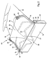
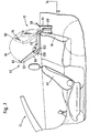
- a first embodiment of an inventive Windstop device which in Fig. 1 as a whole with 10 is designated, this is on a convertible 12th mounted, which is a four-seater.
- the wind stop device 10 comprises a Cartridge element 14 behind rear seats 16 of the convertible vehicle 12 is mounted.
- An interior 18 of the Cassette element 14 serves as a storage space 20 to holder 22nd and wind stop surface elements 24 in a stowed position in FIG to stow the storage space 20, which then out of this can be brought out into a position of use.
- the holders 22 hold the wind stop surface element spanned, forming a wind deflector 25 and a cover 27 for the rear seats 16.
- the second outer pivot bracket 34 pivotally each in an associated pivot bearing 26 arranged.
- the pivot holder 30 and 34 are the wind stop surface elements 24 held.
- the pivot holders 30 and 34 are the wind stop surface elements 24 between the first outer pivot holder 30 and the second outer pivot holder 34 folded so that both the pivot holders 30 and 34 and the Windstop surface elements 24 together in the storage space 20 in a Stowage position 36 are stowable.
- These are preferably the wind stop surface elements 24 from a limp Material made, which is foldable.
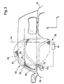
- the first outer pivot holder 30 has a first pivot axis 38, which are mounted in a first pivot bearing 39 is and obliquely to a vehicle longitudinal direction X and a Vehicle transverse direction Y runs.
- the second outer pivot holder 34 which in a second pivot bearing 40 is mounted, a second pivot axis 42, which obliquely to the vehicle longitudinal direction X and the vehicle transverse direction Y runs.
- the run Swivel axes 38 and 42 obliquely to a through the vehicle longitudinal direction X and the vehicle transverse direction Y spanned Level, so that the first pivot axis 38 and the second Pivot axis 42 therefore not parallel or perpendicular to a the excellent spatial directions X or Y or one vertical direction Z lie.
- the pivot holders 30 and 34 have a non-flat bracket shape on. They each include a bracket bearing element 44, which in the associated first and second pivot bearing 39 and 40 is stored. In a deployment position 46, the first outer pivot bracket 30 and the second outer pivot bracket 34 swung against the storage space 20 and form behind front seats 48 of the convertible 12 wind deflector retaining bracket elements 50 for the wind stop surface elements 24, then as a windstop or at least as NASAwindbeskyr act for the wind during movement of the convertible vehicle 12 can.
- Wind deflector retaining bracket element 50 is at an angle ⁇ relative to the vehicle by the longitudinal direction X and the Vehicle transverse direction Y spanned plane oriented, wherein this angle ⁇ is greater than or equal to 90 ° and less than 180 ° and preferably greater than 100 ° and for example in the Range of about 120 ° (Fig. 1).
- This can be the through the wind deflector retaining bracket members 50, the pivot holder 30 and 34 held surface elements substantially in this angle behind the front seats 48 of the convertible 12 position.
- first outer pivot holder 30 and the second outer pivot holder 34 in the insertion position 46 in essentially parallel or at a small acute angle to the vehicle longitudinal direction X oriented cover retaining bracket elements 52, through which the Windstop surface elements 24 in an area above the reminds ⁇ tze 16 of Position the convertible 12. This can be done in the operating position, an area above seating surfaces and cover above padding.
- the through the first outer pivot holder 30 and the second outer pivot holder 34 held Windstop surface elements 24 are arranged on these holders that they are continuously from the wind deflector retaining bracket elements 50 to extend the region of the storage space 20 so that no Wind holes in the use position 46 are present.
- the material for the Windstop surface elements 24 has a conditional wind permeability. Especially it is provided in an embodiment of the invention that the material a Has network structure. However, it is also conceivable that a non-wind-permeable material is used.
- the first outer can be Pivoting holder 30 and by means of the pivot axis 42 of the second outer holder 34 from the stowage position 36 from the storage space 20 in the insertion position 46 for use of Windstop surface elements Swing 24 as a windstop.
- the non-level Forming the pivot holder 30 and 34 with the Storage element 44 and the headband elements 50, 52 is achieved that in the stowed position 36, the headband elements 50 and 52 substantially parallel to a through the vehicle transverse direction Y and by the vertical direction Z lie spanned plane.
- the bracket member 44 has such an angle to Garnierieri 52, that the associated first Pivot axis 38 for the first outer pivot holder 30 and the second pivot axis 42 for the second outer pivot bracket 34 at an intersection (not shown in FIG. 2) to cut. This intersection lies in the direction of a front end of the convertible 12 and above the Swivel bearing 26.
- first Swivel bearing 39 and the second pivot bearing 40 so arranged and are formed such that the first pivot axis 38 and the second pivot axis 42 mirror-symmetrical to a center plane 54 of the convertible 12 are arranged.
- this Intersection is offset from the center plane 54.
- clamping means 58 between the first outer pivot holder 30 and the second outer pivot holder 34 are arranged, which when swinging the pivot holder 30 and 34, a folding of the Windstop surface elements 24 for use as a windstop cause.
- the clamping means are flexible in order to they together with the pivot holders 30 and 34 in the storage space 20 stowable.
- ropes or rubber bands or flexible metal strips or Bowden cables or combinations of these means provided, with one end each at the first outer Pivoting holder 30 and with the other end respectively to the second outer pivot holder 34 are held and with connected to the material for the Windstop surface elements 24 are, for example via fasteners or example woven into this material.
- the storage space 20 has a cover 60 (FIG. 1) which to open and close. With the cover closed 60 are the holders 22 with the Windstop surface elements 24, if they are stowed in the storage space 20, not from the outside recognizable.
- the windstop device according to the invention works as follows:
- the holders 22 are in the storage space 20 sunk and the cover 60 is closed.
- the cover 60th opened the pivot holders 30 and 34 are swung out, until the insertion position 46 is reached. This unfold the wind stop surface elements 24 and are driven by the tensioning means 58 taut, so that behind the front seats 48 of the Cabrio vehicle 12 provided an effective wind stop arrangement is.
- the cover 60 is then closed.
- One end 62 of the pivot holder 30, 34 describes in the case of Pivoting movement from the stowed position 36 in the use position 46 or from the insertion position 46 in the stowed position 36 is a space curve 64 showing the components both in Vehicle longitudinal direction X and vehicle transverse direction Y and in the vertical direction Z has.
- the drive for the swivel holder 30, 34 can thereby electrical, hydraulic or mechanical way.
- the first outer pivot bracket 30 and the second outer pivot bracket 34 separate drives, that is, a first drive 66 for the first outer pivot holder 30 and a second drive (in FIG. 3 for reasons of clarity not shown) for the second outer pivot holder 34, have.
- These drives may be, for example, electric motors act.
- an electronic controller 67 provided, the first drive 66 and the second drive coupled together so that the pivot holder 30 and 34 at the same time pivoted into the insertion position 46 zw in the stowage position 36.
- This electronic Control 67 may preferably also with a Opening and closing mechanism for the cover 60 for be automatically opened and closed.
- Windstop device is provided that the pivoting movement the first outer pivot holder 30 and the pivoting movement the second outer pivot bracket 34 mechanically coupled is.
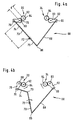
- a lever linkage device 68 is provided (Fig. 4a, b).
- the lever linkage device 68 of the wind stop device according to the invention is arranged in the cassette element 14. It includes a rotatably mounted joint coupling element 70, wherein the Rotary axis 72 of this joint coupling element fixed to the vehicle is.
- the axis of rotation 72 of the joint coupling element 70 is particularly substantially parallel or in a small acute angle to the vehicle longitudinal direction X. aligned.
- a coupled first link rod member 74 which in turn by a further hinge 76 to a sprocket element 78th is hinged, which with a vehicle-fixed axis of rotation 80th is rotatably mounted.
- a hinge point of the joint 76 is located not on the rotation axis 80.
- the sprocket element 78th transmits its rotational movement to a pinion element 82, which also rotatable with a vehicle-fixed axis of rotation 84 is stored.
- the pinion member 82 is rigid with the first outer pivot holder 30 connected and by rotation of the pinion member 82, the pivotal movement of this Swivel holder 30 causes.
- a joint coupling element 70 is further on a joint 86 hinged a second hinge rod member 88.
- This second linkage member 88 is again over another Joint 90 hinged to a second sprocket element 92, which also rotatable with a vehicle-fixed axis of rotation 93 is mounted and by means of a pinion 94, the is rigidly connected to the second outer pivot holder 34, in a rotational movement for pivoting the second outer Swivel holder 34 is displaceable.
- the first hinge rod member 74 is shorter than the second Articulated rod element 88. In this way it is possible to achieve that the first outer pivot holder 30 relative to the second outer pivot holder 34 is swung out a little faster or when swinging back the second outer pivot holder 34th is swung back a little faster than the first outer Swivel holder 30.
- the first sprocket element 78 has namely a greater rotational speed than the second sprocket element 92. This turns the first outer one Schwenkhalter 30 in the same period in a larger Angle of rotation as the second outer pivot holder 34. When Swinging this causes the demonstration of the outer Swivel holder 30, when swiveling the tracking. On this way, a good unfolding or refolding can be reach the windstop surface elements 24.
- a Distance d between the axis of rotation 80 for the sprocket element 78 and the axis of rotation 84 for the pinion 82 is smaller as the distance a between the rotation axis 80 and the rotation axis 72 of the joint coupling element 70.
- the lever linkage device 68 of the windstop device operates as follows:
- the joint coupling element 70 is about the axis of rotation 72nd turned.
- Fig. 4b a movement is shown, the one Pivoting the holder 22 from the stowed position 36 in the Insert position 46 causes.
- the first linkage member 74 and the second linkage member 88 carried. This causes a rotation each of the first sprocket element 78 and the second Sprocket element 92.
- the joint coupling element 70 itself a Drive, such as a worm drive (in Fig. 4 not shown), for effecting the rotational movement of the joint coupling element 70 around the axis of rotation 72 has.
- a Drive such as a worm drive (in Fig. 4 not shown)
- limit switch (not shown in the figures) are provided, which recognize when the insertion position 46 of the holder 22 is reached.
- These Limit switches can, for example, electronic switches such as Protractors include or mechanical elements such as Stop elements.
- the windstop device according to the invention a cassette element 14, in which the storage space 20 is formed, wherein the cassette member 14 fixed to the convertible 12th can be mounted.
- This has a backrest 95 of the rear seats 16 a cavity 96.
- the cavity 96 is formed for example by a hard shell element, the between a backrest cushion of the rear seats 16 and a rear wall of the backrest 95 is arranged.
- the Swiveling the holder 22 in the insertion position 46 and the Stowing the holder 22 in the stowed position 36th works the same way as above described.
- the cover 60 is in a fourth embodiment the windstop device according to the invention formed in several parts. It comprises outer cover elements 98, which in an area above the pivot bearing 26 are arranged, and a one-piece or multi-part cross-cover 100.
- Bei the fourth embodiment shown in Fig. 6 are a first transverse cover element 102 and a second transverse cover element 104 provided.
- the first transverse cover element 102 has a pivot axis 106 and the second Transverse cover element 104 has a pivot axis 108.
- First and second transverse cover elements 102 and 104 leave up and back and / or down and up referred back to the vertical axis Z at their respective Swing swivel axes.
- the outer cover members 98 also respectively Swivel axes 110, which decoupled from the pivot axes 106 and 108 are.
- the outer cover members 98 are thereby pivotally independent of the transverse cover 100, and although relative to the vertical axis Z up and again back.
- the transverse cover elements 102, 104 have a tension against the storage space 20. This is designed so that when swinging the holder 22nd from the stowed position 36 via a drive, the transverse cover elements 102, 104 are opened automatically, that but then, when the deployment position 46 is reached, the Transverse cover elements 102, 104 again automatically by the Close bracing so that no dirt or dust in the empty storage space 20 can get.
- the holder 22 become the outer cover members 98 also opened so far that the pivoting movement allows is and a penetration of dirt in the storage space 20 is largely prevented.
- the cover 60 of the windstop device achieved that in the stowed position, the holder 22 and the Windstop surface elements 24 substantially not visible are and no dirt and the like in the storage space 20th can penetrate and that when extending the Windstop surface elements 24 in the insertion position 46 a high ease of use is reached, since the cover 60 largely automatically closes again.
- the pivot axis 122 can also obliquely to the vehicle transverse direction and optionally obliquely to vertical axis Z run.
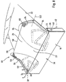
- each of the pivot holder 30, 34 the respective Wind deflector retaining bracket member 50 relative to the cover retaining bracket member 52 movable so that the respective pivot holder 30, 34 in the smallest space in the storage space 20 ' can stow, which is smaller than the storage space, for example in the first embodiment.
- the pivoting of the wind deflector retaining bracket element 50 relative to the cover-retaining element 52 takes place so, that in the use position of the pivot holder 30, 34 respectively the wind deflector retaining bracket member 50 relative to the cover retaining bracket member 52 so sets that the two wind deflector retaining bracket elements 50 of the pivot holder 30, 34 with the of These spanned areas of the Windstop surface element 24 form the wind deflector 25, while that of the cover retaining bracket elements 52 spanned area 27 of the wind stop surface element 24 form the cover for the rear seats 16.
- the pivot holders 30, 34 are of their in Figs. 7 and 8 shown insert positions in their stowed position 36 moves, it is preferably up to Completion of moving the pivot holder 30, 34 of the Insert position in the stowed position pivoting the Wind deflector retaining bracket elements 50 relative to the corresponding Cover retaining bracket members 52 of the above described active position in an inactive position, such as in FIGS. 7, 8 and 9 each shown in dashed lines.
- the pivoting of the wind deflector retaining bracket elements takes place 50 relative to the respective cover retaining bracket elements 52 so far that the wind deflector retaining bracket elements 50 in an inactive position approximately extend parallel to the cover retaining bracket members 52.
- the approximately parallel position of the retaining bracket elements 50, 52nd can be designed so that these in the Z direction one above the other or in X-direction next to each other, whereby each in the other direction the space requirement is minimal.
- the cover retaining bracket elements 52 and the wind deflector retaining bracket elements 50 in the inactive position that is, one of them a recess, for example a U-shaped Recess, has, in which the other in the Inactive position at least partially immersed, thus the Haltebügelemia 50, 52 a minimal space requirement in the Stowage position in the storage space 20 need.
- the retaining bracket elements 50, 52 in the stowed position in the vehicle longitudinal direction X are arranged consecutively, what preferably by a slightly different orientation the pivot axes 38, 42, that is slightly different inclination, is feasible or by an offset of the pivot bearings 39, 40 in the vehicle longitudinal direction X.
- Wind deflector retaining bracket members 50 pivoting the Wind deflector retaining bracket members 50 relative to the cover retaining bracket members 52 before moving the cover retaining bracket elements 52 relative to the convertible, that is a body of the same perform. Is particularly favorable However, when the wind deflector retaining bracket members 50 relative then being moved to the cover retaining bracket members 52, although the cover retaining bracket members 52 around the respective pivot axes 38, 42 are pivoted.
- the Joint 120 is formed so that this one fixed to the Cover retaining bracket member 52 connected stop lug 124 has, against which a stop body 126 can be applied, the fixed to the wind deflector-retaining bracket member 50 is connected is, wherein the stopper body 126 then at the stop lug 124 abuts when the wind deflector retaining bracket member 50 in his active position.
- the wind deflector retaining bracket element 50 is preferably in its active position held by a cable 130, which in the area of a Fixed bearing 132 fixed to the wind deflector-retaining bracket member 50 is connected and via guide elements 134 so on the cover-retaining bracket element 52 is guided that a pulling action of the Cable pull 130, the wind deflector retaining bracket member 50 in his active position.
- the guide elements 134 arranged so that the cable 130 on one of the inactive position of the wind deflector retaining bracket element 50 opposite side of the cover retaining bracket member 52nd is arranged.
- the cable 130 is also still on a vehicle side Fixed bearing 136 out, which, for example, on a support 138 for a bearing block 140 of the respective pivot bearing 39, 40 is arranged.
- the fixed bearing 136 is placed so that the cable from the guide bearing 134c facing the fixed bearing 136 extends to the fixed bearing with a free portion 142, which in the use position of the cover-retaining bracket element 52 is stretched and has a maximum length, so that the cable pull 130 acts on the fixed bearing 132, thus the wind deflector-retaining bracket member 50 due to the Switzerlandbeaufschlagung pivoted into its active position, in which the stopper body 126 at the stop lug 124th is applied.
- the fixed bearing 136 is also arranged so that at a movement of the cover-retaining bracket member 52 of the Deployment position out in the direction of its stowage position free section 142 is increasingly shortened and also finally relaxed and thus the pulling action of the cable 130 decreases to the fixed bearing 136.
- torsion spring 144 which with their two Legs 146 and 148 on both the cover-retaining bracket member 52 as well as on the wind deflector retaining bracket element 50 acts and strives to the angle ⁇ between the two to reduce, takes place with decreasing traction of the Cable 130 an increasing pivoting of the wind deflector retaining bracket element 50 in the direction of the cover retaining bracket element 52 with reduction of the angle ⁇ and that with increasing shortening of the free portion 142 of the cable 130th
- the guide bearing 134c facing the fixed bearing 136 Cable 130 therefore moves in the movement of the Cover retaining bracket member 52 from the insertion position in Direction of stowage position on a track such that the distance between the guide member 134c and the fixed bearing 136 is getting smaller and thus also the free Section 142 can shorten, so that to the extent that Wind deflector retaining bracket element 50 in the direction of the cover retaining bracket element 52 pivots.
- This cable 130 and the arrangement of the fixed bearing 132 and 136 and the Guide elements 134 in the manner described is thus a positively controlled movement of the wind deflector retaining bracket element 50 relative to the cover retaining bracket member 52nd possible, coordinated with the movement of the cover-retaining bracket element 52 from the deployed position to the stowed position and vice versa.
- a elastic tension element 150 is provided, which, for example is designed as a strong spring. This tension element 150 is used the compensation of tolerances and, in the active Position of the wind deflector retaining bracket member 50 relative to Cover retaining bracket member 52 the stopper body 126 always to hold firmly against the stop lug 124, without the tolerances have a negative effect.
- Wind deflector retaining bracket element additionally uncontrolled sag is also an elastic alignment element 152, for example, also in the form of a spring, provided, which transverse to the longitudinal direction of the free portion 142 this affects and serves only, the free Section 142 to prevent sagging, but without a Movement of the wind deflector retaining bracket member 50 relative to Cover retaining bracket member 52 to influence.
- the alignment member 152 is arranged so that it in a Central area acts on the free section 142 and this in the direction of, for example, the bearing block 140 of the Swing bearing 40 applied.
- the insertion position of the cover retaining bracket element 52 is preferably predefined to be able to pretend provided that the bearing block 140 still with an abutment body 160 is provided against which the cover-retaining bracket element 52 can be applied in its position of use.
- the abutment body 160 is positioned so that the Cover retaining bracket member 52 with its directly to the pivot bearing 40 subsequent section, preferably a bent portion 162, on this abutment body 160 can be applied, so that the abutment body 160 still below the windstop device according to the invention provided cover 60 can be arranged.
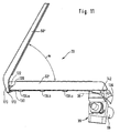
- FIG. 11 In a sixth embodiment, shown in FIG. 11, is shown in a modification to the fifth embodiment in FIGS. 7 to 10, the wind deflector retaining bracket element 50 'in the insertion position designed so that it the corresponding cover-retaining bracket member 52 'a sharp angle, unlike the fifth Embodiment of FIG. 10th
- the wind deflector retaining bracket element 50 is designed such that that it is not just on one side of the joint 120 extends, but with an arm 170 on the joint 120 extends out with the axis of rotation 122 in such a way that the arm 170 in the region of a front end of the respective Cover retaining bracket member 52 is located.
- This allows the cable 130 at a lower end 172 of the arm 170 to attack the pivotal movement of the wind deflector retaining bracket member 50th relative to the cover-holding bracket member 52 to effect.
- the hinge 120 is the same as in the fifth embodiment with the drawing, not shown Provided torsion spring, which endeavors to the angle ⁇ between the wind deflector retaining bracket member 50 'and the Cover retaining clip element 52 'to reduce.
- the cable 130 is in the same manner as in the fifth embodiment by guide elements 134 on the Cover retaining clip element 52 'out and goes into the free section 142 on which in turn with the fixed bearing 136 attacks on the body.
- the tension element 150 in addition to use an over-center position the pivot holder 30, 34 in the use position to obtain.
- the drawn pivot bearing 39 designed so that directly with this the drive motor 66, which serves to cover the cover retaining element 52 'motor-driven about the pivot axis 38 to pivot, wherein by the cable 130 a mechanical Forced control of the pivoting of the wind deflector retaining bracket element 50 'of a parallel to the cover-retaining element 52 'extending stowage position in the in Fig. 11 shown insert position to effect.
- the sixth embodiment is similar like the fifth embodiment, so that in terms Further details on the comments on the fifth Reference is made and the corresponding elements of the sixth embodiment, the same reference numerals as those of the fifth Wear exemplary embodiment.
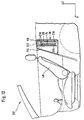
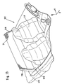
- a seventh embodiment of a device according to the invention which 12 and 13 can be used for two-seater convertible vehicles 212.
- the area above the rear seats 16, which in four-seater convertible vehicles 12 to achieve a good wind stop function must not be covered.
- a cavity 214 is provided, which acts as a storage space 20.
- This cavity 214 has a cover 60 which open and close.
- the holders 22 are in this embodiment as Querschwenkhalter 216, 218 trained.
- the stowed position 36 are in the Cavity 214, the first outer Querschwenkhalter 216 and the second outer Querschwenkhalter 218 arranged.
- the first outer Querschwenkhalter 216 and the second outer Querschwenkhalter 218 are each by means of pivot bearing 220 on the two-seater convertible 212 held.
- pivot axes 222 in this variant of an embodiment in a small acute angle to the vehicle longitudinal direction X oriented.
- the transverse pivot supports 216 and 218 move when swinging into the use position 46 in the small acute angle the Y-Z plane.
- Based on the associated pivot axes 222 have the first outer Querschwenkhalter 216 and the second outer Querschwenkhalter 218 opposite rotational movements.
- the Windstop surface elements 24 unfolded so that they are in the deployment position 46 have a good wind stop function.
- the pivot bearings 220 for the first outer Querschwenkhalter 216 and the second outer Querschwenkhalter 218 offset from each other to a better stowage and folding effect for the Windstop surface elements 24 in the stowed position 36 to reach.
- a cassette element 224 is installed, through whose Interior of the storage space 20 is formed.
- Windstop surface elements 24 by the as Whole set with 58 designated clamping means, which with holder-side ends 58 a, b connected to the holders 22 are.
- the clamping means 58 comprise on the one hand a transverse spreading element 230, which with its holder-side ends 230a, 230b is held on the holders 22, and a contraction element 232, which also has its ends 232a and 232b is held on the holders 22.
- the transverse spreading element 230 is with its ends 230 a, 230 b held at upper ends 233 of the holder 22 and holds the Windstop surface elements 24 in that a Cross spreading element 230 enclosing pocket 234 with her top portion 236 on the between the holders 22nd tensioned transverse spreading element 230 rests.
- the holder 22 from its insertion position in Direction of their stowage position moves in the storage space, like represented by an intermediate position in Fig. 17, so reduces the distance between the holder-side ends 58a, 58b of the clamping means 230, 232 and thereby it goes Cross spreading element 230 of his shown in Fig. 15, im essentially elongate, preferably substantially rectilinear shape in a in Fig.
- Fig. 17 is an extension of the transverse spreading element 230 substantially on one side of the connecting line 240, but it is just as possible form the transverse spreading element so that it is substantially on several sides of the connecting line 240 across this expands.
- the contraction element 232 supports the training the shirred state of the Windstop surface elements 24 by the application of a pulling effect and the endeavor in the Bag 234 to run so that they are as close to the Connecting line 240 extends.
- the distance between the holder side Ends 58a, 58b of the clamping means 58 is reduced and then again increased upon reaching the stowed position, so that in each case in the deployed position as well as in the stowage position the Clamping means 58 are in an extended position. It is it is not necessary that the stretched position of the clamping means 58 in the stowed position the same distance between the Holder-side ends 58a, 58b has as in the use position.
- the transverse spreading element 230 is a helical one wound wire rope or a helically wound wire used, which in the untensioned state, the helical shape and extending into a substantially elongated Let state tension so that the individual turns 238 of the same in the exploded state substantially straight are drawn. It is important that the transverse spreading element not made of a material which is not tense state limp sagging, but in one defined form passes, but a sufficient flexibility of form has to be in a substantially to be able to pass over a stretched state.
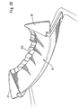
- FIGS. 18 to 20 are to form a defined top line 250, preferably with an upwardly convex convex contour
- the windstop surface elements 24 are provided with a comb 252, which is made of a material with a certain inherent rigidity is made so that the comb 252 in the deployed position the holder 22 also in its use position stands and the desired convex upward curved top line 250 of the wind stop surface elements 24 through its upper edge 251 forms.
- top edge is still with an additional toothing 254, comprising upwardly projecting portions 256 and opposite these recessed areas 258, provided, which serves to prevent the formation of wind noise or mitigate.
- the comb 252 is for example off Rubber material is manufactured and overlaps or forms, as in the exploded view in Fig. 19 recognizable, to the Windstop surface elements 24 molded pocket 234, in which the tensioning means 58 run.
- the tensioning means 58 in this case also comprise the Cross spreading element 230, the contraction element 232 and still an additional alignment element 260 which is spaced from the transverse spreading element 230 is arranged and thus together with the transverse spreading element 230 for a defined orientation of the comb 252 provides, so that this in the use position of Holder 22 is held tilt-free.
- the alignment element 260 is likewise designed such that that it is in the position of use between the holders 22nd is curious.
- the alignment element 260 may be either off be a limp material or also from one Material with an inherent rigidity, which is analogous to Transverse spread element merges into a defined shape when the distance between the holder-side ends 58a, b of the Clamping means 58 reduced.
- Another way to Realization of the alignment member 260 is the, this as Contraction element corresponding to the contraction element 232 train.
- the comb 252 is around that of the transverse spreading element 230 predetermined shape change in reducing the distance between the holder-side ends 58a, b to join can, with bends 262, for example, with bodies lesser material thickness, provided in regular Distances along the extension of the comb 252 between the Holders 22 are arranged so that at these bends 262 the possibility of bending the comb 252 is given and
- the comb 252 of the Cross spreading element 230 may follow predetermined change in shape, when the distance between the holders 22 at the transition reduced from the use position in the stowed position.
- the transverse spreading element 230 the same effect with regard to the entrainment of Windstop surface elements 24 unfold, as described above Connection with the ninth embodiment (FIGS 17) has been described.
- the comb 252 is formed so that between the bends 262, the individual sections 264 of the comb 252 have a relatively large stiffness and thus in essential despite the action of the transverse spreading element 230 their Maintain shape.
Landscapes
- Engineering & Computer Science (AREA)
- Mechanical Engineering (AREA)
- Fittings On The Vehicle Exterior For Carrying Loads, And Devices For Holding Or Mounting Articles (AREA)
- Seats For Vehicles (AREA)
- Devices Affording Protection Of Roads Or Walls For Sound Insulation (AREA)
Description
- Fig. 1
- einen schematischen Längsschnitt eines Cabriofahrzeuges, mit einem ersten Ausführungsbeispiel einer erfindungsgemäßen Windstop-Einrichtung;
- Fig. 2
- eine schematische perspektivische Ansicht der erfindungsgemäßen Windstop-Einrichtung ausgehend von einer Karosserierückseite;
- Fig. 3
- eine Hinteransicht eines Cabriofahrzeugs mit montierter erfindungsgemäßen Windstop-Einrichtung;
- Fig. 4a, b
- eine schematische Darstellung eines Kopplungsantriebs zur Bewegung der Halter bei einem zweiten Ausführungsbeispiel der erfindungsgemäßen Windstop-Einrichtung;
- Fig. 5
- einem Längsschnitt ähnlich Fig. 1 durch ein drittes Ausführungsbeispiel einer erfindungsgemäßen Windstop-Einrichtung;
- Fig. 6
- eine Draufsicht auf eine Abdeckung für einen Verstauraum bei einem vierten Ausführungsbeispiel;
- Fig. 7
- einen Längsschnitt ähnlich Fig. 1 durch ein fünftes Ausführungsbeispiel;
- Fig. 8
- eine perspektivische Ansicht ähnlich Fig. 2 des fünften Ausführungsbeispiels;
- Fig. 9
- eine Hinteransicht ähnlich Fig. 3 des fünften Ausführungsbeispiels;
- Fig. 10
- eine vergrößerte Darstellung eines Halters des fünften Ausführungsbeispiels in Seitenansicht mit Blickrichtung von einer Karosserieinnenseite zu einer Karosserieaußenseite;
- Fig. 11
- eine vergrößerte Darstellung eines Halters eines sechsten Ausführungsbeispiels ähnlich Fig. 10 mit Blickrichtung von einer Karosserieaußenseite zu einer Karosserieinnenseite;
- Fig. 12
- einen Längsschnitt ähnlich Fig. 1 durch ein siebtes Ausführungsbeispiel einer Windstop-Einrichtung für ein Zweisitzer-Cabriofahrzeug. Jedoch nicht mit Haltern die ent- sprechend Anspruch 1 schwenkbar sind;
- Fig. 13
- eine schematische perspektivische Ansicht von in ihrer wirksamen Stellung positionierten Windstop-Flächenelementen des siebten Ausführungsbeispiels bei einem Zweisitzer-Cabriofahrzeug;
- Fig. 14
- einen Längsschnitt ähnlich Fig. 1 durch ein achtes Ausführungsbeispiel für eine erfindungsgemäße Windstop-Einrichtung für ein Zweisitzer-Cabriofahrzeug;
- Fig. 15
- eine schematische perspektivische Ansicht eines neunten Ausführungsbeispiels einer erfindungsgemäßen Windstop-Einrichtung, gesehen von einer Karosserievorderseite;
- Fig. 16
- einen Schnitt längs Linie 16-16 in Fig. 15;
- Fig. 17
- eine perspektivische Ansicht ähnlich Fig. 15 beim Bewegen der Windstop-Einrichtung von der Einsatzposition in Richtung einer Verstauposition mit Darstellung einer Formänderung eines Querspreizelements und der Auswirkung auf die Windstop-Flächenelemente;
- Fig. 18
- eine schematische Darstellung ähnlich Fig. 15 eines zehnten Ausführungsbeispiels;
- Fig. 19
- eine Explosionsdarstellung des zehnten Ausführungsbeispiels gemäß Fig. 18 mit abgenommenem Kamm; und
- Fig. 20
- eine Darstellung ähnlich Fig. 17 mit Formänderung des Kamms bedingt durch das Querspreizelement.
Claims (71)
- Windstop-Einrichtung für ein Cabriofahrzeug, umfassend Windstop-Flächenelemente (24), welche in einem Bereich hinter Vordersitzen des Cabriofahrzeugs positionierbar sind, Halter (22) zum Halten der Windstop-Flächenelemente in ihrer wirksamen Stellung, welche am Cabriofahrzeug montierbar sind, wobei die Halter (22) relativ zum Cabriofahrzeug (12) derart gelagert sind, daß in einer Einsatzposition (46) der Halter (22) die Windstop-Flächenelemente (24) in der wirksamen Stellung stehen und in einer Verstauposition (36) die Halter (22) mit den Windstop-Flächenelementen (24) in einem im Cabriofahrzeug (12) angeordneten Verstauraum (20) verstaut sind, .
dadurch gekennzeichnet, daß Schwenkachsen (38, 42) der Halter (22) jeweils schräg zu der Fahrzeuglängsrichtung (X) und schräg zur Fahrzeugquerrichtung (Y) orientiert sind. - Windstop-Einrichtung nach Anspruch 1, dadurch gekennzeichnet, daß die Halter (22) sich in der Verstauposition (36) quer zu einer Fahrzeuglängsrichtung (X) erstrecken.
- Windstop-Einrichtung nach Anspruch 1 oder 2, dadurch gekennzeichnet, daß die Halter (22) relativ zum Verstauraum (20) schwenkbar sind.
- Windstop-Einrichtung nach einem der voranstehenden Ansprüche,
dadurch gekennzeichnet, daß die Schwenkachsen (38, 42) jeweils schräg zu einer vertikalen Richtung (Z) orientiert sind. - Windstop-Einrichtung nach einem der voranstehenden Ansprüche,
dadurch gekennzeichnet, daß Schwenkachsen (38, 42) für die Halter (22) schräg zu einer durch eine Fahrzeuglängsrichtung (X) und einer Fahrzeugquerrichtung (Y) aufgespannten Ebene (X-Y-Ebene) orientiert sind. - Windstop-Einrichtung nach Anspruch 5, dadurch gekennzeichnet, daß ein Schwenkachsenvektor der Schwenkachsen (38, 42), dessen Projektion auf die vertikale Richtung (Z) parallel zu dieser ist, in Richtung eines Fahrzeuginnenraums bezogen auf die Fahrzeugquerrichtung und in Richtung eines hinteren Fahrzeugendes bezogen auf die Fahrzeuglängsrichtung (X) orientiert ist.
- Windstop-Einrichtung nach einem der Ansprüche 3 bis 6, dadurch gekennzeichnet, daß die Windstop-Einrichtung Schwenklager (26) zur Lagerung der Halter (22) umfaßt, welche an dem Cabriofahrzeug (12) innerhalb des Verstauraumes (20) montiert sind.
- Windstop-Einrichtung nach einem der Ansprüche 3 bis 7, dadurch gekennzeichnet, daß die Windstop-Einrichtung einen ersten äußeren Schwenkhalter (30), welcher in einem ersten Schwenklager (39) gelagert ist, und einen zweiten äußeren Schwenkhalter (34), welcher in einem zweiten Schwenklager (40) gelagert ist, umfaßt, wobei jeweilige Verlängerungslinien einer ersten Schwenkachse (38) des ersten äußeren Halters (30) und einer zweiten Schwenkachse (42) des zweiten äußeren Halters (34) einen Schnittpunkt aufweisen.
- Windstop-Einrichtung nach Anspruch 8, dadurch gekennzeichnet, daß der Schnittpunkt innerhalb einer Mittenebene (54) des Cabriofahrzeuges (12), welche senkrecht zur Fahrzeugquerrichtung (Y) ist, liegt.
- Windstop-Einrichtung nach Anspruch 8, dadurch gekennzeichnet, daß der Schnittpunkt gegenüber einer Mittenebene (54) des Cabriofahrzeuges (12), welche senkrecht zur Fahrzeugquerrichtung (Y) ist, versetzt ist.
- Windstop-Einrichtung nach einem der voranstehenden Ansprüche, dadurch gekennzeichnet, daß jeder Halter (22) ein Windschott-Haltebügelelement (50) und ein Abdeckungs-Haltebügelelement (52) aufweist.
- Windstop-Einrichtung nach Anspruch 11, dadurch gekennzeichnet, daß das Windschott-Haltebügelelement (50) relativ zum Abdeckungs-Haltebügelelement (52) von einer aktiven Stellung in eine inaktive Stellung und umgekehrt bewegbar ist.
- Windstop-Einrichtung nach Anspruch 12, dadurch gekennzeichnet, daß das Windschott-Haltebügelelement (50) in der aktiven Stellung in seiner die Windstop-Flächenelemente (24) in der wirksamen Stellung haltenden Stellung steht und in der inaktiven Stellung in einer nahe dem Abdeckungs-Haltebügelelement (52) liegenden Stellung.
- Windstop-Einrichtung nach Anspruch 13, dadurch gekennzeichnet, daß das Windschott-Haltebügelelement (50) in seiner inaktiven Stellung ungefähr parallel zum Abdeckungs-Haltebügelelement ausgerichtet ist.
- Windstop-Einrichtung nach einem der Ansprüche 12 bis 14, dadurch gekennzeichnet, daß das Windschott-Haltebügelelement (50) in der Einsatzposition der Halter (30, 34) in der aktiven Stellung steht und in der Verstauposition der Halter (30, 34) in der inaktiven Stellung.
- Windstop-Einrichtung nach Anspruch 15, dadurch gekennzeichnet, daß das Windschott-Haltebügelelement (50) mit der Bewegung der Halter (22) von der Verstauposition in die Einsatzposition koordiniert von der inaktiven Stellung in die aktive Stellung bewegbar ist.
- Windstop-Einrichtung nach Anspruch 16, dadurch gekennzeichnet, daß das Windschott-Haltebügelelement (50) während der Bewegung der Halter (22) von der Verstauposition in die Einsatzposition von der inaktiven Stellung in die aktive Stellung bewegbar ist.
- Windstop-Einrichtung nach Anspruch 16 oder 17, dadurch gekennzeichnet, daß das Windschott-Haltebügelelement (50) zwangsgesteuert mit der Bewegung der Halter (22) bewegbar ist.
- Windstop-Einrichtung nach einem der Ansprüche 15 bis 18 dadurch gekennzeichnet, daß die Bewegung des Windschott-Haltebügelelements (50) mechanisch mit der Bewegung der Halter (22) gekoppelt ist.
- Windstop-Einrichtung nach Anspruch 19, dadurch gekennzeichnet, daß die Bewegung des Windschott-Haltebügelelements (50) durch ein Zugelement (130) mechanisch mit der Bewegung der Halter (22) gekoppelt ist.
- Windstop-Einrichtung nach Anspruch 20, dadurch gekennzeichnet, daß das Zugelement (130) einen in Zugrichtung wirksamen elastischen Kraftspeicher (150) aufweist.
- Windstop-Einrichtung nach Anspruch 20 oder 21, dadurch gekennzeichnet, daß ein freier Abschnitt (142) des Zugelements (130) im entspannten Zustand in einer vorgegebenen Richtung gehalten ist.
- Windstop-Einrichtung nach einem der Ansprüche 19 bis 22, dadurch gekennzeichnet, daß das Windschott-Haltebügelelement (50) durch ein elastisches Element (144) relativ zum Abdeckungs-Haltebügelelement (52) in Richtung seiner inaktiven Stellung beaufschlagt ist.
- Windstop-Einrichtung nach Anspruch 2, dadurch gekennzeichnet, daß die Schwenkachsen (222) in einem kleinen spitzen Winkel zur Fahrzeuglängsrichtung (X) orientiert sind.
- Windstop-Einrichtung nach Anspruch 24, dadurch gekennzeichnet, daß ein erstes Schwenklager, in welchem ein erster äußerer Querschwenkhalter (216) gelagert ist, bezogen auf eine Fahrzeuglängsrichtung (X) versetzt gegen ein zweites Schwenklager, in welchem ein zweiter äußerer Querschwenkhalter (218) gelagert ist, angeordnet ist.
- Windstop-Einrichtung nach einem der vorangehenden Ansprüche, dadurch gekennzeichnet, daß die Halter (22) so ausgebildet sind, daß in der Einsatzposition (46) Windstop-Flächenelemente (24) im wesentlichen parallel zur Fahrzeugquerrichtung (Y) und in einem Winkel (α) zur durch die Fahrzeuglängsrichtung (X) und die Fahrzeugquerrichtung (Y) aufgespannte Ebene orientiert sind.
- Windstop-Einrichtung nach Anspruch 26, dadurch gekennzeichnet, daß der Winkel (α) gemessen im Gegenuhrzeigersinn gegenüber der durch die Fahrzeuglängsrichtung (X) und die Fahrzeugquerrichtung (Y) aufgespannten Ebene größer oder gleich 90° und kleiner als ca. 180° ist.
- Windstop-Einrichtung nach Anspruch 26 oder 27, dadurch gekennzeichnet, daß die Halter so ausgebildet sind, daß in der Einsatzposition (46) Windstop-Flächenelemente (24) von einem an einem den Vordersitzen (48) zugewandten Ende der Halter (22) liegenden Bereich bis zu einem Bereich des Verstauraums (20) angeordnet sind.
- Windstop-Einrichtung nach einem der vorangehenden Ansprüche, dadurch gekennzeichnet, daß das Material für die Windstop-Flächenelemente (24) ein faltbares Material ist.
- Windstop-Einrichtung nach einem der vorangehenden Ansprüche, dadurch gekennzeichnet, daß das Material für die Windstop-Flächenelemente (24) eine bedingte Winddurchlässigkeit aufweist.
- Windstop-Einrichtung nach Anspruch 30, dadurch gekennzeichnet, daß das Material für die Windstop-Flächenelemente (24) eine Netzstruktur aufweist.
- Windstop-Einrichtung nach einem der Ansprüche 29 bis 31, dadurch gekennzeichnet, daß die Windstop-Einrichtung Spannmittel (58) aufweist, welche ein Aufspannen der Windstop-Flächenelemente (24) beim Bewegen der Halter (22) aus dem Verstauraum (20) in die Einsatzposition (46) bewirken.
- Windstop-Einrichtung nach Anspruch 32, dadurch gekennzeichnet, daß die Spannmittel (58) ein sich bei abnehmendem Abstand zwischen dessen halterseitigen Enden (58a, b) durch Formänderung in Richtung quer zu einer Verbindungslinie (240) zwischen den halterseitigen Enden (230a, b) ausdehnendes Querspreizelement (230) umfassen.
- Windstop-Einrichtung nach Anspruch 33, dadurch gekennzeichnet, daß das Querspreizelement (230) sich durch Bildung von quer zur Verbindungslinie (240) verlaufenden Ausbiegungen (238) quer zur Verbindungslinie (240) ausdehnt.
- Windstop-Einrichtung nach Anspruch 33 oder 34, dadurch gekennzeichnet, daß das Querspreizelement (230) als Ausbiegungen mehrere Bögen (238) bildet.
- Windstop-Einrichtung nach einem der Ansprüche 33 bis 35, dadurch gekennzeichnet, daß das Querspreizelement (230) mäanderähnliche Bögen (238) bildet.
- Windstop-Einrichtung nach einem der Ansprüche 33 bis 35, dadurch gekennzeichnet, daß das Querspreizelement (230) wendelartige Bögen (238) bildet.
- Windstop-Einrichtung nach einem der Ansprüche 33 bis 37, dadurch gekennzeichnet, daß das Querspreizelement (230) aus einem formflexiblen, nichtschlaffen Material ist.
- Windstop-Einrichtung nach einem der Ansprüche 33 bis 38, dadurch gekennzeichnet, daß das Querspreizelement (230) aus einem Strangmaterial ist, welches von einer quer zur Verbindungslinie (240) der Enden (230a, b) ausgedehnten Form durch Vergrößern des Abstands der Enden (230a, b) in eine gestreckte Form mit quer zur Verbindungslinie (240) reduzierten Ausdehnung bringbar ist.
- Windstop-Einrichtung nach einem der Ansprüche 33 bis 39, dadurch gekennzeichnet, daß das Spannmittel (58) in einer schlauchförmigen mit den Windstop-Flächenelementen (24) verbundenen Tasche (234) verläuft.
- Windstop-Einrichtung nach Anspruch 40, dadurch gekennzeichnet, daß die Tasche (234) aus dem Material der Windstop-Flächenelemente (24) gebildet ist.
- Windstop-Einrichtung nach Anspruch 40 oder 41, dadurch gekennzeichnet, daß das Spannmittel (58) lose in der Tasche (234) verläuft.
- Windstop-Einrichtung nach einem der Ansprüche 40 bis 42, dadurch gekennzeichnet, daß die Tasche (234) eine zumindest begrenzte Querausdehnung des Spannmittels (58) zuläßt.
- Windstop-Einrichtung nach einem der Ansprüche 32 bis 43, dadurch gekennzeichnet, daß die Spannmittel (58) ein zwischen den Haltern (22) angeordnetes flexibles Verbindungselement umfassen, welches die Windstop-Flächenelemente (24) in der Einsatzposition (46) spannt.
- Windstop-Einrichtung nach einem der Ansprüche 33 bis 44, dadurch gekennzeichnet, daß die Spannmittel (58) ein in Richtung einer Verringerung des Abstands zwischen den halterseitigen Enden (58a, b) wirkendes Kontraktionselement (232) aufweisen.
- Windstop-Einrichtung nach Anspruch 45, dadurch gekennzeichnet, daß das Kontraktionselement (232) ein zugelastischer Strang ist.
- Windstop-Einrichtung nach einem der voranstehenden Ansprüche, dadurch gekennzeichnet, daß die Windstop-Flächenelemente (24) als oberen Abschluß einen Kamm (252) tragen.
- Windstop-Einrichtung nach Anspruch 47, dadurch gekennzeichnet, daß der Kamm (252) eine konvex nach oben gewölbte Oberlinie (250) bildet.
- Windstop-Einrichtung nach Anspruch 47 oder 48, dadurch gekennzeichnet, daß der Kamm (252) eine gezahnte obere Begrenzungslinie (254) aufweist.
- Windstop-Einrichtung nach einem der Ansprüche 47 bis 49, dadurch gekennzeichnet, daß der Kamm (252) faltbar ist.
- Windstop-Einrichtung nach einem der Ansprüche 47 bis 50, dadurch gekennzeichnet, daß der Kamm (252) aus einem nichtschlaffem Material hergestellt ist.
- Windstop-Einrichtung nach einem der Ansprüche 47 bis 51, dadurch gekennzeichnet, daß der Kamm (252) durch die Spannmittel (58) ausgerichtet gehalten ist.
- Windstop-Einrichtung nach einem der vorangehenden Ansprüche, dadurch gekennzeichnet, daß der Verstauraum (20) durch einen Innenraum (18) eines Kassettenelementes (14, 224) gebildet ist, welches an dem Cabriofahrzeug (12; 212) montierbar ist.
- Windstop-Einrichtung nach Anspruch 53, dadurch gekennzeichnet, daß Lager (26; 220) für die Bewegung der Halter (22, 216, 218) an dem Kassettenelement (14; 224) montiert sind.
- Windstop-Einrichtung nach einem der vorangehenden Ansprüche, dadurch gekennzeichnet, daß der Verstauraum (20) eine Abdeckung (60) aufweist, welche sich öffnen und schließen läßt.
- Windstop-Einrichtung nach einem der vorangehenden Ansprüche, dadurch gekennzeichnet, daß der Verstauraum (20) hinter Rücksitzen (16) des Cabriofahrzeuges (12) im Cabriofahrzeug (12) angeordnet ist.
- Windstop-Einrichtung nach einem der vorangehenden Ansprüche, dadurch gekennzeichnet, daß der Verstauraum in Rücksitzen des Cabriofahrzeugs (12) integriert ist.
- Windstop-Einrichtung nach einem der Ansprüche 1 bis 55, dadurch gekennzeichnet, daß der Verstauraum (20) hinter den Vordersitzen (48) des Cabriofahrzeuges (212) angeordnet ist.
- Windstop-Einrichtung nach einem der vorangehenden Ansprüche, dadurch gekennzeichnet, daß die Windstop-Einrichtung einen Antrieb (66; 78) zum Schwenken der Halter (22) aufweist.
- Windstop-Einrichtung nach Anspruch 59, dadurch gekennzeichnet, daß ein erster äußerer Schwenkhalter (30) durch einen ersten Antrieb (66; 78) und ein zweiter äußerer Schwenkhalter (34) durch einen zweiten Antrieb (92) angetrieben sind.
- Windstop-Einrichtung nach Anspruch 60, dadurch gekennzeichnet, daß der erste und der zweite Antrieb mittels einer Steuerung (67) koppelbar sind.
- Windstop-Einrichtung nach Anspruch 60, dadurch gekennzeichnet, daß der erste Antrieb (78) für den einen Halter (22) und der zweite Antrieb (92) für den anderen Halter (22) mechanisch gekoppelt sind.
- Windstop-Einrichtung nach Anspruch 62, dadurch gekennzeichnet, daß die mechanische Kopplung durch eine Hebelgestängevorrichtung (68) gebildet ist, welche ein Gelenkkopplungselement (70) aufweist, das drehbar mit einer fahrzeugfesten Drehachse (72) gelagert ist und wobei eine Drehbewegung dieses Gelenkkopplungselementes (70) umsetzbar ist in eine Schwenkbewegung des ersten (30) und des zweiten (34) äußeren Halters.
- Windstop-Einrichtung nach Anspruch 63, dadurch gekennzeichnet, daß an das Gelenkkopplungselement (70) ein erstes Gelenkstangenelement (74) angelenkt ist, welches an ein fahrzeugfest drehbar gelagertes erste Zahnkranzelement (78) außerhalb dessen Drehachse (80) angelenkt ist, wobei durch das erste Zahnkranzelement (78) der erste Antrieb für den ersten äußeren Halter (30) gebildet ist, und daß an das Gelenkkopplungselement (70) ein zweites Gelenkstangenelement (88) angelenkt ist, welches an ein fahrzeugfest drehbar gelagertes zweites Zahnkranzelement (92) außerhalb dessen Drehachse angelenkt ist, wobei durch das zweite Zahnkranzelement (92) der zweite Antrieb für den zweiten äußeren Halter (34) gebildet ist.
- Windstop-Einrichtung nach Anspruch 64, dadurch gekennzeichnet, daß das erste Gelenkstangenelement (74) bezogen auf den Abstand zwischen entsprechenden Gelenkpunkten (73, 76; 86, 90) kürzer ist als das zweite Gelenkstangenelement (88).
- Windstop-Einrichtung nach Anspruch 64 oder 65, dadurch gekennzeichnet, daß in der Verstauposition (36) das erste Gelenkstangenelement (74) im wesentlichen kolinear zur Richtung zwischen Anlenkpunkten (73, 86) des ersten Gelenkstangenelements (74) und des zweiten Gelenkstangenelementes (88) an dem Gelenkkopplungselement (70) orientiert ist und das zweite Gelenkstangenelement (88) quer zu dieser Richtung orientiert ist.
- Windstop-Einrichtung nach einem der Ansprüche 64 bis 66, dadurch gekennzeichnet, daß der erste (30) und der zweite (34) äußere Schwenkhalter jeweils starr mit einem fahrzeugfest drehbar angeordneten Ritzelelement (82, 94) verbunden sind, welches jeweils zur Übertragung der Drehbewegung des ersten (78) und zweiten (92) Zahnkranzelements auf die jeweiligen Schwenkhalter (30, 34) dient.
- Windstop-Einrichtung nach Anspruch 67, dadurch gekennzeichnet, daß ein Abstand (d) zwischen einer Ritzelelementdrehachse (82) und zugehöriger Zahnkranzelementdrehachse (80) kleiner ist als ein Abstand (a) zwischen der Zahnkranzelementdrehachse (80) und einer Gelenkkopplungselementdrehachse (72) des Gelenkkopplungselementes (70).
- Windstop-Einrichtung nach einem der Ansprüche 64 bis 68, dadurch gekennzeichnet, daß das Gelenkkopplungselement (70) mittels eines Schneckentriebs drehbar ist.
- Windstop-Einrichtung nach einem der Ansprüche 59 bis 69, dadurch gekennzeichnet, daß der Antrieb (66; 78, 92) der Halter (22) von einer Fahrgastzelle des Cabriofahrzeuges (12; 212) aus betätigbar ist.
- Windstop-Einrichtung nach einem der Ansprüche 59 bis 70, dadurch gekennzeichnet, daß der Antrieb (66; 78, 92) mit einem Öffnungs- und Schließmechanismus für eine Abdeckung (60) des Verstauraumes (20) gekoppelt ist.
Applications Claiming Priority (4)
| Application Number | Priority Date | Filing Date | Title |
|---|---|---|---|
| DE19727206 | 1997-06-26 | ||
| DE19727206 | 1997-06-26 | ||
| DE19735158 | 1997-08-13 | ||
| DE19735158A DE19735158A1 (de) | 1997-06-26 | 1997-08-13 | Windstop-Einrichtung |
Publications (3)
| Publication Number | Publication Date |
|---|---|
| EP0887217A2 EP0887217A2 (de) | 1998-12-30 |
| EP0887217A3 EP0887217A3 (de) | 1999-06-09 |
| EP0887217B1 true EP0887217B1 (de) | 2005-03-30 |
Family
ID=26037770
Family Applications (1)
| Application Number | Title | Priority Date | Filing Date |
|---|---|---|---|
| EP98111880A Expired - Lifetime EP0887217B1 (de) | 1997-06-26 | 1998-06-26 | Windstop-Einrichtung |
Country Status (2)
| Country | Link |
|---|---|
| EP (1) | EP0887217B1 (de) |
| AT (1) | ATE292026T1 (de) |
Families Citing this family (14)
| Publication number | Priority date | Publication date | Assignee | Title |
|---|---|---|---|---|
| DE19902242A1 (de) * | 1999-01-21 | 2000-08-03 | Oris Fahrzeugteile Riehle H | Windstopeinrichtung |
| DE19923306A1 (de) * | 1999-05-21 | 2000-11-23 | Bayerische Motoren Werke Ag | Windschott |
| DE29911995U1 (de) * | 1999-07-09 | 2000-11-23 | Wilhelm Karmann GmbH, 49084 Osnabrück | Windschott |
| US6926062B2 (en) | 2000-03-13 | 2005-08-09 | Oris Fahrzeugteile Hans Riehle Gmbh | Screen element for motor vehicles; in particular, wind blocker |
| DE10053701A1 (de) * | 2000-10-24 | 2002-05-08 | Oris Fahrzeugteile Riehle H | Windstopeinrichtung |
| DE10061562A1 (de) | 2000-12-04 | 2002-06-13 | Oris Fahrzeugteile Riehle H | Windschott |
| DE102005048740B4 (de) * | 2005-10-10 | 2017-08-17 | Webasto SE | Windschotteinrichtung eines Fahrzeugs mit einem schwenkbar gelagerten Windschott |
| DE102006008653A1 (de) * | 2006-02-24 | 2007-08-30 | Wilhelm Karmann Gmbh | Windstoppeinrichtung für ein Cabrioletfahrzeug |
| DE102006052096A1 (de) * | 2006-11-04 | 2008-05-08 | Dr.Ing.H.C. F. Porsche Ag | Windschott und Cabriolet mit einem solchen Windschott |
| GB2443616A (en) * | 2006-11-07 | 2008-05-14 | Ford Global Tech Llc | Contoured net rear windscreen for a convertible vehicle |
| DE102009058611B4 (de) * | 2009-12-17 | 2021-06-10 | Volkswagen Ag | Verstauanordnung für ein Windschott eines Cabriolets |
| GB201820560D0 (en) | 2018-12-17 | 2019-01-30 | Aston Martin Lagonda Ltd | Assemblies for engines |
| EP3954561B1 (de) * | 2020-08-14 | 2023-11-15 | Inalfa Roof Systems Group B.V. | Windablenkanordnung |
| DE102025141326A1 (de) | 2025-10-09 | 2026-05-21 | Bayerische Motoren Werke Aktiengesellschaft | Windschottvorrichtung für einen Kraftwagen sowie Kraftwagen |
Family Cites Families (2)
| Publication number | Priority date | Publication date | Assignee | Title |
|---|---|---|---|---|
| DE4119529A1 (de) * | 1991-06-13 | 1992-12-17 | Bayerische Motoren Werke Ag | Cabriolet mit einem windschutz |
| DE9206644U1 (de) * | 1992-05-15 | 1992-07-23 | Oris-Metallbau KG Hans Riehle, 7141 Möglingen | Rolloanordnung bei Kraftwagen, insbesondere bei Cabrios |
-
1998
- 1998-06-26 AT AT98111880T patent/ATE292026T1/de not_active IP Right Cessation
- 1998-06-26 EP EP98111880A patent/EP0887217B1/de not_active Expired - Lifetime
Also Published As
| Publication number | Publication date |
|---|---|
| EP0887217A2 (de) | 1998-12-30 |
| EP0887217A3 (de) | 1999-06-09 |
| ATE292026T1 (de) | 2005-04-15 |
Similar Documents
| Publication | Publication Date | Title |
|---|---|---|
| EP1128973B1 (de) | Faltverdeck für einen kraftwagen | |
| EP1884390B1 (de) | Windschott für ein Kraftfahrzeug und Kraftfahrzeug mit einem solchen Windschott | |
| DE4481036B4 (de) | Sonnenschutz für das Dach eines Automobils | |
| EP0395847B1 (de) | Antriebseinrichtung für ein motorisch angetriebenes Klappverdeck | |
| DE10108493B4 (de) | Antriebsvorrichtung für ein Klappverdeck und Klappverdeck für ein Cabriolet-Fahrzeug mit einer solchen Antriebsvorrichtung | |
| EP1449692A1 (de) | Sonnenschutzsystem für ein Kraftfahrzeug | |
| EP1737689B1 (de) | Faltverdeck für ein cabriolet-fahrzeug sowie cabriolet-fahrzeug mit einem faltverdeck | |
| DE19942428A1 (de) | Verdeck für ein Cabriolet | |
| DE19911541B4 (de) | Faltverdeck für einen Kraftwagen | |
| DE19939954B4 (de) | Faltschiebedachanordnung | |
| EP1864841B1 (de) | Cabriolet mit einem Windschott als Abdeckung für einen Verdeckaufnahmeraum | |
| EP0887217A2 (de) | Windstop-Einrichtung | |
| DE10063150B4 (de) | Sonnenschutzanordnung für ein Fahrzeugdach | |
| DE102021119568B3 (de) | Vorrichtung zum Betreiben einer Bildschirmanordnung für ein Fahrzeugdach und Fahrzeugdach für ein Kraftfahrzeug | |
| WO2023006650A1 (de) | Vorrichtung zum betreiben einer bildschirmanordnung für ein fahrzeugdach und fahrzeugdach für ein kraftfahrzeug | |
| EP1918147A2 (de) | Windschott und Cabriolet mit einem solchen Windschott | |
| EP1132241B1 (de) | Cabriolet-Fahrzeug mit einem unterhalb eines Verdeckkastendeckels ablegbaren Verdeck | |
| DE10229808A1 (de) | Verdeck für ein Cabriolet-Fahrzeug | |
| WO2023006654A1 (de) | Vorrichtung zum betreiben einer bildschirmanordnung für ein fahrzeugdach und fahrzeugdach für ein kraftfahrzeug | |
| DE10063056A1 (de) | Sonnenschutzanordnung für ein Fahrzeugdach | |
| DE10025401B4 (de) | Sonnenschutzeinrichtung | |
| DE10331143B4 (de) | Fahrzeugdach mit einer Dachöffnung und einer bewegbaren Dachschließeinrichtung | |
| DE102007054469B4 (de) | Fahrzeugverdeck | |
| DE102021119553A1 (de) | Vorrichtung zum Betreiben einer Bildschirmanordnung für ein Fahrzeugdach und Fahrzeugdach für ein Kraftfahrzeug | |
| DE102021119561A1 (de) | Vorrichtung zum Betreiben einer Bildschirmanordnung für ein Fahrzeugdach und Fahrzeugdach für ein Kraftfahrzeug |
Legal Events
| Date | Code | Title | Description |
|---|---|---|---|
| PUAI | Public reference made under article 153(3) epc to a published international application that has entered the european phase |
Free format text: ORIGINAL CODE: 0009012 |
|
| AK | Designated contracting states |
Kind code of ref document: A2 Designated state(s): AT BE CH DE ES FR GB IT LI NL |
|
| AX | Request for extension of the european patent |
Free format text: AL;LT;LV;MK;RO;SI |
|
| PUAL | Search report despatched |
Free format text: ORIGINAL CODE: 0009013 |
|
| AK | Designated contracting states |
Kind code of ref document: A3 Designated state(s): AT BE CH CY DE DK ES FI FR GB GR IE IT LI LU MC NL PT SE |
|
| AX | Request for extension of the european patent |
Free format text: AL;LT;LV;MK;RO;SI |
|
| 17P | Request for examination filed |
Effective date: 19990811 |
|
| AKX | Designation fees paid |
Free format text: AT BE CH DE ES FR GB IT LI NL |
|
| 17Q | First examination report despatched |
Effective date: 20010601 |
|
| GRAP | Despatch of communication of intention to grant a patent |
Free format text: ORIGINAL CODE: EPIDOSNIGR1 |
|
| GRAS | Grant fee paid |
Free format text: ORIGINAL CODE: EPIDOSNIGR3 |
|
| GRAA | (expected) grant |
Free format text: ORIGINAL CODE: 0009210 |
|
| AK | Designated contracting states |
Kind code of ref document: B1 Designated state(s): AT BE CH DE ES FR GB IT LI NL |
|
| PG25 | Lapsed in a contracting state [announced via postgrant information from national office to epo] |
Ref country code: NL Free format text: LAPSE BECAUSE OF FAILURE TO SUBMIT A TRANSLATION OF THE DESCRIPTION OR TO PAY THE FEE WITHIN THE PRESCRIBED TIME-LIMIT Effective date: 20050330 |
|
| REG | Reference to a national code |
Ref country code: GB Ref legal event code: FG4D Free format text: NOT ENGLISH |
|
| PGFP | Annual fee paid to national office [announced via postgrant information from national office to epo] |
Ref country code: GB Payment date: 20050331 Year of fee payment: 8 |
|
| REG | Reference to a national code |
Ref country code: CH Ref legal event code: EP |
|
| REF | Corresponds to: |
Ref document number: 59812689 Country of ref document: DE Date of ref document: 20050504 Kind code of ref document: P |
|
| PGFP | Annual fee paid to national office [announced via postgrant information from national office to epo] |
Ref country code: AT Payment date: 20050525 Year of fee payment: 8 |
|
| PG25 | Lapsed in a contracting state [announced via postgrant information from national office to epo] |
Ref country code: LI Free format text: LAPSE BECAUSE OF NON-PAYMENT OF DUE FEES Effective date: 20050630 Ref country code: CH Free format text: LAPSE BECAUSE OF NON-PAYMENT OF DUE FEES Effective date: 20050630 Ref country code: BE Free format text: LAPSE BECAUSE OF NON-PAYMENT OF DUE FEES Effective date: 20050630 |
|
| PG25 | Lapsed in a contracting state [announced via postgrant information from national office to epo] |
Ref country code: ES Free format text: LAPSE BECAUSE OF FAILURE TO SUBMIT A TRANSLATION OF THE DESCRIPTION OR TO PAY THE FEE WITHIN THE PRESCRIBED TIME-LIMIT Effective date: 20050711 |
|
| NLV1 | Nl: lapsed or annulled due to failure to fulfill the requirements of art. 29p and 29m of the patents act | ||
| GBT | Gb: translation of ep patent filed (gb section 77(6)(a)/1977) |
Effective date: 20050912 |
|
| PLBE | No opposition filed within time limit |
Free format text: ORIGINAL CODE: 0009261 |
|
| STAA | Information on the status of an ep patent application or granted ep patent |
Free format text: STATUS: NO OPPOSITION FILED WITHIN TIME LIMIT |
|
| REG | Reference to a national code |
Ref country code: CH Ref legal event code: PL |
|
| ET | Fr: translation filed | ||
| 26N | No opposition filed |
Effective date: 20060102 |
|
| PG25 | Lapsed in a contracting state [announced via postgrant information from national office to epo] |
Ref country code: GB Free format text: LAPSE BECAUSE OF NON-PAYMENT OF DUE FEES Effective date: 20060626 Ref country code: AT Free format text: LAPSE BECAUSE OF NON-PAYMENT OF DUE FEES Effective date: 20060626 |
|
| PGFP | Annual fee paid to national office [announced via postgrant information from national office to epo] |
Ref country code: IT Payment date: 20060630 Year of fee payment: 9 |
|
| GBPC | Gb: european patent ceased through non-payment of renewal fee |
Effective date: 20060626 |
|
| BERE | Be: lapsed |
Owner name: ORIS FAHRZEUGTEILE HANS RIEHLE G.M.B.H. Effective date: 20050630 |
|
| REG | Reference to a national code |
Ref country code: FR Ref legal event code: TP |
|
| PG25 | Lapsed in a contracting state [announced via postgrant information from national office to epo] |
Ref country code: IT Free format text: LAPSE BECAUSE OF NON-PAYMENT OF DUE FEES Effective date: 20070626 |
|
| PGFP | Annual fee paid to national office [announced via postgrant information from national office to epo] |
Ref country code: FR Payment date: 20100709 Year of fee payment: 13 |
|
| REG | Reference to a national code |
Ref country code: FR Ref legal event code: ST Effective date: 20120229 |
|
| PG25 | Lapsed in a contracting state [announced via postgrant information from national office to epo] |
Ref country code: FR Free format text: LAPSE BECAUSE OF NON-PAYMENT OF DUE FEES Effective date: 20110630 |
|
| REG | Reference to a national code |
Ref country code: DE Ref legal event code: R082 Ref document number: 59812689 Country of ref document: DE Representative=s name: HOEGER, STELLRECHT & PARTNER PATENTANWAELTE, DE |
|
| REG | Reference to a national code |
Ref country code: DE Ref legal event code: R082 Ref document number: 59812689 Country of ref document: DE Representative=s name: HOEGER, STELLRECHT & PARTNER PATENTANWAELTE MB, DE Effective date: 20150407 Ref country code: DE Ref legal event code: R082 Ref document number: 59812689 Country of ref document: DE Representative=s name: HOEGER, STELLRECHT & PARTNER PATENTANWAELTE, DE Effective date: 20150407 Ref country code: DE Ref legal event code: R081 Ref document number: 59812689 Country of ref document: DE Owner name: BOSAL ACPS HOLDING 2 B.V., NL Free format text: FORMER OWNER: SCAMBIA INDUSTRIAL DEVELOPMENTS AKTIENGESELLSCHAFT, SCHAAN, LI Effective date: 20150407 Ref country code: DE Ref legal event code: R081 Ref document number: 59812689 Country of ref document: DE Owner name: SCAMBIA HOLDINGS CYPRUS LTD., CY Free format text: FORMER OWNER: SCAMBIA INDUSTRIAL DEVELOPMENTS AKTIENGESELLSCHAFT, SCHAAN, LI Effective date: 20150407 |
|
| REG | Reference to a national code |
Ref country code: DE Ref legal event code: R082 Ref document number: 59812689 Country of ref document: DE Representative=s name: HOEGER, STELLRECHT & PARTNER PATENTANWAELTE MB, DE |
|
| PGFP | Annual fee paid to national office [announced via postgrant information from national office to epo] |
Ref country code: DE Payment date: 20170621 Year of fee payment: 20 |
|
| REG | Reference to a national code |
Ref country code: DE Ref legal event code: R082 Ref document number: 59812689 Country of ref document: DE Representative=s name: HOEGER, STELLRECHT & PARTNER PATENTANWAELTE MB, DE Ref country code: DE Ref legal event code: R081 Ref document number: 59812689 Country of ref document: DE Owner name: BOSAL ACPS HOLDING 2 B.V., NL Free format text: FORMER OWNER: SCAMBIA HOLDINGS CYPRUS LTD., LIMASSOL, CY |
|
| REG | Reference to a national code |
Ref country code: DE Ref legal event code: R071 Ref document number: 59812689 Country of ref document: DE |