EP0887519B1 - Ventilsteuerungseinrichtung für eine Brennkraftmaschine - Google Patents
Ventilsteuerungseinrichtung für eine Brennkraftmaschine Download PDFInfo
- Publication number
- EP0887519B1 EP0887519B1 EP98111557A EP98111557A EP0887519B1 EP 0887519 B1 EP0887519 B1 EP 0887519B1 EP 98111557 A EP98111557 A EP 98111557A EP 98111557 A EP98111557 A EP 98111557A EP 0887519 B1 EP0887519 B1 EP 0887519B1
- Authority
- EP
- European Patent Office
- Prior art keywords
- rocker arm
- support
- valve operating
- oil passage
- bore
- Prior art date
- Legal status (The legal status is an assumption and is not a legal conclusion. Google has not performed a legal analysis and makes no representation as to the accuracy of the status listed.)
- Expired - Lifetime
Links
- 238000002485 combustion reaction Methods 0.000 title claims description 31
- 239000010687 lubricating oil Substances 0.000 claims description 85
- 238000004891 communication Methods 0.000 claims description 51
- 239000003921 oil Substances 0.000 claims description 42
- 238000001746 injection moulding Methods 0.000 claims description 12
- 239000002184 metal Substances 0.000 claims description 11
- 238000005096 rolling process Methods 0.000 claims description 10
- 230000004044 response Effects 0.000 claims description 7
- 230000008878 coupling Effects 0.000 claims description 2
- 238000010168 coupling process Methods 0.000 claims description 2
- 238000005859 coupling reaction Methods 0.000 claims description 2
- 230000009467 reduction Effects 0.000 description 13
- 230000015572 biosynthetic process Effects 0.000 description 8
- 230000007246 mechanism Effects 0.000 description 5
- 230000003245 working effect Effects 0.000 description 5
- 238000003780 insertion Methods 0.000 description 4
- 230000037431 insertion Effects 0.000 description 4
- 239000011230 binding agent Substances 0.000 description 2
- 230000001747 exhibiting effect Effects 0.000 description 2
- 238000004898 kneading Methods 0.000 description 2
- 239000008188 pellet Substances 0.000 description 2
- 230000003014 reinforcing effect Effects 0.000 description 2
- 150000001875 compounds Chemical class 0.000 description 1
- 238000005553 drilling Methods 0.000 description 1
- 238000010438 heat treatment Methods 0.000 description 1
- 238000003754 machining Methods 0.000 description 1
- 238000012986 modification Methods 0.000 description 1
- 230000004048 modification Effects 0.000 description 1
- 238000000465 moulding Methods 0.000 description 1
- 239000000843 powder Substances 0.000 description 1
- 238000007493 shaping process Methods 0.000 description 1
- 238000005245 sintering Methods 0.000 description 1
Images





Classifications
-
- F—MECHANICAL ENGINEERING; LIGHTING; HEATING; WEAPONS; BLASTING
- F01—MACHINES OR ENGINES IN GENERAL; ENGINE PLANTS IN GENERAL; STEAM ENGINES
- F01L—CYCLICALLY OPERATING VALVES FOR MACHINES OR ENGINES
- F01L1/00—Valve-gear or valve arrangements, e.g. lift-valve gear
- F01L1/26—Valve-gear or valve arrangements, e.g. lift-valve gear characterised by the provision of two or more valves operated simultaneously by same transmitting-gear; peculiar to machines or engines with more than two lift-valves per cylinder
- F01L1/267—Valve-gear or valve arrangements, e.g. lift-valve gear characterised by the provision of two or more valves operated simultaneously by same transmitting-gear; peculiar to machines or engines with more than two lift-valves per cylinder with means for varying the timing or the lift of the valves
-
- F—MECHANICAL ENGINEERING; LIGHTING; HEATING; WEAPONS; BLASTING
- F01—MACHINES OR ENGINES IN GENERAL; ENGINE PLANTS IN GENERAL; STEAM ENGINES
- F01L—CYCLICALLY OPERATING VALVES FOR MACHINES OR ENGINES
- F01L2305/00—Valve arrangements comprising rollers
- F01L2305/02—Mounting of rollers
Definitions
- the present invention relates to a valve operating system in an internal combustion engine, in which a support shaft is mounted to extend between first and second support walls included in a rocker arm, and the rocker arm is urged by an urging means in a direction to bring a roller into rolling contact with a valve operating cam.
- a valve operating system of the above type is already known from Japanese Patent Publication No. 2-50286 and the like.
- a receiving portion is provided at a widthwise central portion of the rocker arm in a direction parallel to the axis of a rocker shaft on which the rocker arm is swingably supported.
- the receiving portion is positioned at the central portion of the rocker arm, despite the provision of the roller, the structure of the rocker arm is complicated, and the size of the rocker arm is increased, resulting in an increased weight.
- a valve operating system according to the preamble of claim 1 is disclosed in DE 4 433 457 A.
- a valve operating system in an internal combustion engine comprising a cam shaft provided with a valve operating cam, a rocker arm having first and second support walls opposed to each other at a distance, a support shaft mounted to extend between the support walls, a roller rollably supported on the support shaft through a bearing, and an urging means for urging the rocker arm in a direction to bring the roller into rolling contact with the valve operating cam, wherein one of the support walls included in the rocker arm is integrally provided with a receiving portion which contacts with the urging means, said receiving portion and a support portion of one of said support walls for supporting said support shaft being provided on a common plane extending perpendicular to the axis of the support shaft.
- the structure of the rocker arm can be simplified such that the receiving portion is positioned to the side of the roller, and an increase in size of the rocker arm can be avoided and further, the inertial weight is reduced.
- the structure of the rocker arm can be simplified such that the receiving portion is positioned to the side of the roller, and an increase in size of the rocker arm can be avoided and further, the inertial weight is reduced.
- the valve operating system includes the cam shaft provided with a plurality of valve operating cams, a plurality of the rocker arms positioned adjacent one another, and an associative operation switching means for switching between a state in which the rocker arms adjacent each other operated together associatively and a state in which the associative operation is released, and the first and second support walls are provided on the free rocker arm of the free of rocker arm, which becomes free relative to an engine valve, when the associative operation switching means is brought into the associative operation releasing state.
- the structure of the free rocker arm can be simplified such that the receiving portion is positioned to the side of the roller, and an increase in size of the rocker arm can be avoided and further, the inertial weight is reduced.
- the structure of the free rocker arm can be simplified such that the receiving portion is positioned to the side of the roller, and an increase in size of the rocker arm can be avoided and further, the inertial weight is reduced.
- the first support wall of in the free rocker arm has a first fitting bore provided therein, one end of the support shaft being fitted into the first fitting bore, and the second support wall having the receiving portion includes a second fitting bore therein coaxially with the first fitting bore, the other end of the support shaft being fitted into the second fitting bore, the first support wall having an insert bore leading to an inner surface of the first fitting bore, the support shaft having an engage groove in an outer surface thereof in correspondence to an opening of the insert bore into the inner surface of the first fitting bore, and a pin engaged in the engage groove , the pin being inserted into and fitted in the insert bore.
- the axial movement of the support shaft and the rotation of the support shaft about its axis are inhibited by the pin, whereby the support shaft is easily fixed.
- the size and the position of the insert bore are not limited by the receiving portion.
- the rocker arms are positioned adjacent one another, so that the other rocker arm different from the free rocker arm is positioned at one end in the direction of arrangement of the rocker arms
- the associative operation switching means includes hydraulically operated pistons, and switches between the associative operation and the releasing of the associative operation of the rocker arms in response to the operation of the pistons due to a variation in hydraulic pressure in a hydraulic pressure chamber defined in the other rocker arm
- the support shaft has a cylindrical shape to guide the sliding operation of the pistons
- the free rocker arm is supported on a support member with the first support wall being positioned on the side of the other rocker arm.
- one of the first and second support walls of the free rocker arm having the receiving portion includes a lubricating oil passage for supplying lubricating oil from an oil passage in a support member for supporting the free rocker arm for swinging movement, to the bearing of the free rocker arm.
- a support member for supporting the rocker arm is provided with an oil passage, and the first and second support walls include fitting bores for fixing opposite ends of the support shaft, respectively.
- the rocker arm has a lubricating oil passage which opens into an inner surface of at least one of the fitting bores in the rocker arm and which leads to the oil passage in the support member, and at least the one of the fitting bores has a groove in its inner surface with one end leading to the lubricating oil passage and with other end opening toward the bearing.
- lubricating oil is supplied from the oil passage in the support member through the lubricating oil passage and the groove to the bearing.
- the oil passage structure for supplying lubricating oil to the bearing can be easily formed and moreover, it is unnecessary to drill the support shaft for introducing the lubricating oil. Therefore, there is no reduction in rigidity of the support shaft, and further, the number of workings is reduced.
- a support member for supporting the rocker arm has an oil passage, wherein at least one of the first and second support walls includes a lubricating oil passage which leads to the oil passage in the support member and opens toward the bearing.
- the lubricating oil is supplied from the oil passage in the support member through the lubricating oil passage to the bearing.
- the lubricating oil passage is only in at least one of the support walls included in the rocker arm.
- the oil passage structure for supplying lubricating oil to the bearing can be easily formed and moreover, it is unnecessary to drill the support shaft for introducing the lubricating oil. Therefore, there is not a possibility of reduction in rigidity of the support shaft, and further, the number of workings is reduced.
- the cam shaft has a plurality of valve operating cams, including at least one high-speed valve operating cam, and a plurality of the rocker arms positioned adjacent one another, the rocker arms including a first particular rocker arm operatively coupled to the high-speed valve operating cam, the high-speed valve operating cam having a cam profile for permitting the maximum lift amount of the engine valve, and an associative operation switching means including pistons movable between a position in which the rocker arms positioned adjacent each other, are operated in association with each other, and a position in which the associative operation is released, wherein the first and second support walls in at least the first particular rocker the arm of the plurality of the rocker arms include with fitting bores spaced from and coaxially opposed to each other, and the support shaft is of a cylindrical shape to guide the sliding operation of the pistons and has opposite ends fitted into and fixed in the fitting bores, a support member supporting the first particular rocker arm, the support member having an oil passage, the first particular rocker arm
- the lubricating oil is supplied from the oil passage in the support member through the lubricating oil passage and the groove to the bearing which is positioned between the support shaft of the first particular rocker arm corresponding to the high-speed valve operating cam, i.e., the rocker arm having a relatively large inertial weight and the roller.
- the load on the bearing can be alleviated.
- the oil passage structure for supplying the lubricating oil to the bearing can be easily formed and moreover, it is unnecessary to drill the support shaft for introducing the lubricating oil. Therefore, there is no reduction in rigidity of the support shaft, and further, the number of workings is reduced.
- the lubricating oil passage is provided in one of the support walls, the other support wall is provided with an insert bore which extends to an inner surface of the fitting bore included in the other support wall, the support shaft has an engage groove in its outer surface corresponding to an opening of the insert bore into an inner surface of the fitting bore, and a pin engaged in the engage groove is inserted into and fixed in the insert bore.
- the insert bore is provided at a location relatively far apart from the lubricating oil passage which is hollow. This is convenient for the rigidity of the rocker arm.
- the rocker arms are positioned adjacent one another such manner that the other rocker arm different from the first particular rocker arm is positioned at one end in the direction of arrangement of the rocker arms, the other rocker arm including a hydraulic pressure chamber, and the associative operation switching means includes pistons for switching between the associative operation and the releasing of the associative operation of the rocker arms in response to the operation of the pistons resulting from a variation in hydraulic pressure in the hydraulic pressure chamber, the other rocker arm including an insert bore in one of the support walls included in the first particular rocker arm, which is positioned adjacent the other rocker arm, the insert bore extending to an inner surface of the fitting bore such support wall, the support shaft having an engage groove on its outer surface corresponding to an opening of the insert bore into the fitting bore, the system including a pin engaged in the engage groove being inserted into and fixed in the insert bore, the lubricating oil passage being provided in one of the support walls, which is positioned at a location spaced apart from the other rock
- the insert bore is at the location relatively far apart from the lubricating oil passage which is hollow. This is convenient for the rigidity of the first particular rocker arm.
- the support shaft is fixed to the first particular rocker arm at a location in which the piston included in the associative operation switching means is inserted and hence, the insertion of the piston into the support shaft, i.e., the switching operation of the associative operation switching means, is smooth.
- the lubricating oil passage has a cross-sectional shape with a length longer in the direction substantially perpendicular to the axis of the cam shaft than a length in the direction substantially parallel to the axis of the cam shaft.
- the rocker arm is formed from a metal by injection molding.
- the fitting bore and the lubricating oil passage can be formed simultaneously with the formation of the rocker arm, and the number of post-workings can be reduced to a minimum to enhance the productivity.
- the valve operating system includes a plurality of the rocker arms positioned adjacent one another, one of the rocker arms having a receiving portion; and the system includes an associative operation switching means having a timing piston defining a hydraulic pressure chamber between the timing piston and a second particular rocker arm of the rocker arms, the associative operation switching means switching the associative operation and the releasing of the associative operation of the rocker arms in response to the operation of the timing piston as a response of a variation in hydraulic pressure in the hydraulic pressure chamber, the system further including a support member for supporting the second particular rocker arm for swinging movement the support member having an oil passage the second particular rocker arm having a communication passage for operatively coupling the oil passage with the hydraulic pressure chamber, the communication passage having a cross-sectional shape with a length in a direction substantially perpendicular to the direction of arrangement of the rocker arms longer than the length in a direction substantially parallel to the direction of arrangement of the rocker arms, the communication passage extending in a plane substantially per
- a cylindrical support shaft is fixed to the second particular rocker arm, the second rocker arm including a first support wall having a first closed fitting bore therein, and a second support wall having a second fitting bore therein coaxial with the first fitting bore, opening at the opposite end thereof, the cylindrical support shaft having opposite ends fitted into the first and second fitting bores; and a roller in rolling contact with one of a plurality of the valve operating cams and which is rollably supported on the cylindrical support shaft, the timing piston being swingably fitted on the cylindrical support shaft, and the communication passage being positioned in the first support wall of the second particular rocker arm.
- the support shaft has a notch in that portion at one end thereof, which corresponds to the communication passage, and the notch has a shape corresponding to the communication passage.
- the communication passage can be positioned in proximity to the roller, while ensuring a sufficient contact area of the support shaft with the first fitting bore in the first support wall to ensure the support strength of the support shaft on the second particular rocker arm, and thus, the size of the second particular rocker arm can be further reduced.
- the second support wall of the second particular rocker arm has an insert bore therein, leading to an inner surface of the second fitting bore;
- the cylindrical support shaft has an engage groove in the outer surface thereof corresponding to the opening of the insert bore into the inner surface of the second fitting bore;
- the system including a pin engaged in the engage groove and inserted into and fixed in the insert bore.
- the second particular rocker arm includes a bulge portion on the outer surface thereof at one end in the direction of the arrangement of the rocker arms, the bulging portion bulging outwards to define the communication passage therein, and the second particular rocker arm includes a rib on the outer surface, and connecting a side edge of the outer surface, the bulge portion.
- the second particular rocker arm is formed from metal by injection molding.
- FIG. 1 A first embodiment of the present invention will be described with reference to Figs. 1 to 11.
- a pair of intake valve bores 12 are provided for each of cylinders in a cylinder head 11 in a multi-cylinder engine, e.g., a serial 4-cylinder internal combustion engine.
- the intake valve bores 12 are individually opened and closed by intake valves V as engine valves.
- the intake valves V have stems 13 which are slidably received in guide tubes 14 provided in the cylinder head 11.
- Valve springs 16 are mounted between retainers 15 at upper ends of the stems 13 protruding upwards from the guide tubes 14 and the cylinder head 11 to surround the stems 13, so that the intake valves V are biased by spring forces of the valve spring in a direction to close the intake valve bores 12.
- a valve operating device 17 is connected to the intake valves V and includes a cam shaft 18 operatively connected to a crankshaft (which is not shown) at a reduction ratio of 1/2, a first driving rocker arm 19 as a second particular rocker arm, which is operatively connected to one of the intake valves V, a second driving rocker arm 20 operatively connected to the other intake valve V, a free rocker arm 21 as a first particular rocker arm, which is capable of becoming free relative to the intake valves V.
- a stationary rocker shaft 22 as a support member, commonly supports the rocker arms 19, 20 and 21 for swinging movement and has an axis parallel to the cam shaft 18.
- An associative operation switching means 23 switches the associative operation and the release of the associative operation of the rocker arms 19, 20 and 21.
- a high-speed valve operating cam 26 and lower-speed valve operating cams 25 are fixedly provided on the cam shaft 18.
- the lower-speed valve operating cams 25 are positioned on opposite sides of the high-speed valve operating cam 26 in correspondence to the intake valves V, respectively.
- the high-speed valve operating cam 26 has a cam profile permitting the intake valves V to be opened and closed in a high-speed operational range of the engine, and includes an arcuate base circle-portion 26a about the axis of the cam shaft 18, and a cam lobe 26b protruding radially outwards from the base circle-portion 26a.
- the low-speed valve operating cam 25 has a cam profile permitting the intake valves V to be opened and closed in a lower-speed operational range of the engine, and includes a base circle-portion 25a formed into an arcuate shape about the axis of the cam shaft 18, and a cam lobe 25b which protrudes outwards radially of the cam shaft 18 from the base circle-portion 25a at an protrusion amount smaller than that of the cam lobe 26b from the base circle-portion 26a in the high-speed valve operating cam 26 and over a range of center angle narrower than that of the cam lobe 26b.
- the high-speed valve operating cam 26 has a cam profile ensuring a lift amount of the intake valve V larger than that of the low-speed valve operating cam 25.
- the first driving rocker arm 19, the second driving rocker arm 20 and the free rocker arm 21 are positioned adjacent one another such that the free rocker arm 21 is interposed between the first and second driving rocker arms 19 and 20, and the arms 19, 20 and 21 are swingably supported commonly by the rocker shaft 22.
- the first and second driving rocker arms 19 and 20 are integrally provided with arm portions 19a and 20a extending toward the intake valves V. Tappet screws 27 abutting against the upper ends of the stems 13 of the intake valves V, are threadedly engaged with tip ends of the arm portions 19a and 20a for advancing and retreating movements.
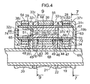
- An opening 34 is provided in the first driving rocker arm 19 between the rocker shaft 22 and the tappet screw 27, and opens on upper and lower sides to form, on opposite sides, first and second support walls 31 1 and 31 2 opposed to each other in a direction parallel to the axis of the rocker shaft 22.
- a cylindrical roller 28 in rolling contact with the low-speed valve operating cam 25 is rollably supported on the first driving rocker arm 19 such that it is positioned in the opening 34.
- An opening 35 is provided in the second driving rocker arm 20 between the rocker shaft 22 and the tappet screw 27, and opens on upper and lower sides to form, on opposite sides, first and second support walls 32 1 and 32 2 opposed to each other in a direction parallel to the axis of the rocker shaft 22.
- a cylindrical roller 29 in rolling contact with the low-speed valve operating cam 25 is rollably supported on the second driving rocker arm 20 such that it is positioned in the opening 35.
- an opening 36 is provided in the free rocker arm 21 and opens on the opposite side from the rocker shaft 22 and on upper and lower sides to form, on opposite sides, first and second support walls 33 1 and 33 2 opposed to each other in a direction parallel to the axis of the rocker shaft 22.
- a cylindrical roller 30 in rolling contact with the high-speed valve operating cam 26 is rollably supported on the free rocker arm 21 such that it is positioned in the opening 36.
- a first fitting bore 37 1 opening toward the free rocker arm 21, is provided in the first support wall 31 1 of the first driving rocker arm 19 in parallel to the axis of the rocker shaft 22, and a second fitting bore 37 2 opening on opposite ends is provided in the second support wall 31 2 coaxially with the first fitting bore 37 1 .
- a first fitting bore 38 1 opening on opposite ends is provided in the first support wall 32 1 of the second driving rocker arm 20 on the side of the free rocker arm 21, in parallel to the axis of the rocker shaft 22, and a second closed end fitting bore 382 opening toward the free rocker arm 21, is provided in the second support wall 32 2 coaxially with the first fitting bore 38 1 .
- a first fitting bore 39 1 opening at opposite ends is provided in the first support wall 33 1 of the free rocker arm 21 on the side of the first driving rocker arm 19 in parallel to the axis of the rocker shaft 22, and a second fitting bore 39 2 opening at opposite ends is provided in the second support wall 33 2 coaxially with the first fitting bore 39 1 .
- One end of a cylindrical support shaft 41 is fitted into the first fitting bore 37 1 in the first driving rocker arm 19, until it abuts against the closed end of the first fitting bore 37 1 , and the other end of the support shaft 41 is fitted into the second fitting bore 37 2 .
- One end of a cylindrical support shaft 42 is fitted into the first fitting bore 38 1 in the second driving rocker arm 20, and the other end of the support shaft 42 is fitted into the second fitting bore 38 2 , until it abuts against the closed end of the second fitting bore 38 2 .
- opposite ends of a cylindrical support shaft 43 are fitted into the first and second fitting bores 39 1 and 39 2 in the free rocker arm 21, respectively.
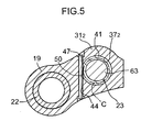
- an insert bore 44 is provided in the second support wall 31 2 of the first driving rocker arm 19, and extends in a direction intersecting a straight line connecting axes of the rocker shaft 22 and the second fitting bore 37 2 to lead to an inner surface of the second fitting bore 37 2 .
- An engage groove 50 is provided in an outer surface of the support shaft 41 in correspondence to an opening of the insert bore 44 into the inner surface of the second fitting bore 37 2 , and extends along a direction tangent to a phantom circle C about the axis of the support shaft 41.
- a pin 47 is inserted into and fixed in the insert bore 44, for example, by press-fitting such that an intermediate portion thereof engages into the engage groove 50, whereby the support shaft 41 is fixed to the first driving rocker arm 19.
- the support shaft 42 is fixed to the first support wall 32 1 of the second driving rocker arm 20 in a structure similar to a structure for fixing the support shaft 41 to the first driving rocker arm 19. More specifically, a pin 48 inserted into and fixed in an insert bore 45 provided in the first support wall 32 1 of the second driving rocker arm 20 is engaged in an engage groove 51 provided in an outer surface of the support shaft 42 fitted in the first fitting bore 38 1 .
- the support shaft 43 is fixed to the first support wall 33 1 of the free rocker arm 21 in a structure similar to the structure for fixing the support shaft 41 to the first driving rocker arm 19 and a structure for fixing the support shaft 42 to the second driving rocker arm 20. More specifically, a pin 49 inserted into and fixed in an insert bore 46 provided in the first support wall 33 1 of the free rocker arm 21, is engaged into an engage groove 52 provided in an outer surface of the support shaft 43 fitted in the first fitting bore 39 1 .
- a needle bearing 53 is interposed between the roller 28 and the support shaft 41 between the first and second support walls 31 1 and 31 2 of the first driving rocker arm 19.
- a needle bearing 54 is interposed between the roller 29 and the support shaft 42 between the first and second support walls 32 1 and 32 2 of the second driving rocker arm 20.
- a needle bearing 55 is interposed between the roller 30 and the support shaft 43 between the first and second support walls 33 1 and 33 2 of the free rocker arm 21.
- a lost motion mechanism 58 is provided in the cylinder head 11 below the free rocker arm 21 and serves as an urging means for applying an urging force to the free rocker arm 21 in a direction to bring the roller of the free rocker arm 21 into rolling contact with the high-speed valve operating cam 26.
- the lost motion mechanism 58 comprises a closed end cylindrical lifter 60 slidably fitted in a closed end slide bore 59 provided in the cylinder head 11, with its upper portion opened, and a spring 61 mounted between the closed end of the slide bore 59 and the lifter 60.
- the free rocker arm 21 includes a receiving portion 62 which is in contact with an upper end of the lifter to receive the spring force from the lost motion mechanism 58.
- the pin 49 is inserted and fixed in the insert bore 46 to fix the support shaft 43 to one of the first and second support walls 33 1 and 33 2 included in the free rocker arm 21, the receiving portion 62 is integrally provided in a lower portion of the second support wall 33 2 to bulge downwards.
- the associative operation switching means 23 includes a timing piston 63 capable of switching the associative operation and the releasing of the associative operation of the first driving rocker arm 19 and the free rocker arm 21 adjoining each other, a cylindrical switching piston 64 capable of the associative operation and the releasing of the associative operation of the free rocker arm 21 and the second driving rocker arm 20 adjoining each other, a closed end cylindrical limiting member 65 which is in contact with the switching piston 64 on the opposite side from the timing piston 63, and a return spring 66 for biasing the limiting member 65 toward the switching piston 64.
- the timing piston 63 is slidably fitted in the support shaft 41 of the first driving rocker arm 19, and a hydraulic pressure chamber 67 is defined between the closed end of the first fitting bore 37 1 in which one end of the support shaft 41 is fitted, and one end of the timing piston 63.
- An oil passage 68 is provided, for example, coaxially in the rocker shaft 22, and connected to a hydraulic pressure source through a control valve which is not shown.
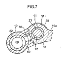
- a communication bore 69 is provided in the rocker shaft 22 to permit a communication passage 70 provided in the first support wall 33 1 of the first driving rocker arm 19 with its one end leading to the hydraulic chamber 67, to be normally put into communication with the oil passage 68.
- the communication passage 70 is provided in the first driving rocker arm 19 on the side of the first support wall 31 1 , to extend in a plane substantially perpendicular to a direction of arrangement of the rocker arms 19, 20 and 21, and has a cross-sectional shape with a length longer in the direction perpendicular to the direction of arrangement of the rocker arms 19, 20 and 21, i.e., in a direction perpendicular to the axes of the cam shaft 18 and the rocker shaft 22, than a length in a direction along the direction of arrangement of the rocker arms 19, 20 and 21, i.e., in a direction along the axes of the cam shaft 18 and the rocker shaft 22.
- the communication bore 69 is provided in the rocker shaft 22, and extends greater in a circumferential direction of the rocker shaft 22 than it extends in communication with the communication passage 70, in order to normally put the oil passage 68 into the communication passage 70, irrespective of the swinging state of the first driving rocker arm 19. Moreover, the other end of the communication passage 70 opens into a side of the first driving rocker arm 19, and an intermediate portion of the communication passage 70 is cut off by the rocker shaft 22.
- a bulge portion 19b bulging outwards to define the communication passage 70 is provided on an outer surface of the first driving rocker arm 19 at one end in the direction of arrangement of the rocker arms 19, 20 and 21, and a plurality of, e.g. two, ribs 71 are provided between a side edge 19c and the bulge portion 19b of the outer surface of the first driving rocker arm 19.
- the communication passage 70 is provided in the first driving rocker arm 19 in such a manner that a portion thereof is positioned nearer to the roller 28 than one end of the support shaft 41 in a direction parallel to the axis of the rocker shaft 22.
- a notch 72 having a shape corresponding to the communication passage is provided at a portion of the one end of the support shaft corresponding to the communication passage 70.
- the switching piston 64 is slidably fitted in the support shaft 43 of the free rocker arm 21, with one end of the switching piston 64 being in contact with the other end of the timing piston 63 for sliding movement relative to each other.
- the limiting member 65 is formed into a cylindrical shape having one closed end and slidably fitted into the support shaft 42 of the second driving rocker arm 20, with the closed end of the limiting member 65 being in contact with the other end of the switching piston 64 for sliding movement relative to each other.
- a retaining ring 73 is mounted on an inner surface of the support shaft 42 to abut against the limiting member 65 for preventing the limiting member 65 from dropping from the support shaft 42.
- the return spring 66 is mounted between the closed end of the second fitting bore 38 2 in the second driving rocker arm 20 and the limiting member 65, and an open bore 74 is formed in the closed end of the second fitting bore 38 2 .
- the hydraulic pressure in the hydraulic pressure chamber 67 is relative low, and contact faces of the timing piston 63 and the switching piston 64 lie at a location between the first driving rocker arm 19 and the free rocker arm 21, while contact faces of the switching piston 64 and the limiting member 65 lie at a location between the free rocker arm 21 and the second driving rocker arm 20. Therefore, the rocker arms 19, 20 and 21 are in relatively swingable states, so that the intake valves V are opened and closed with a timing and in a lift amount depending upon the low-speed valve operating cams 25.
- a lubricating oil passage 76 1 normally leading to the oil passage 68 in the rocker shaft 22 is provided in one of the support walls 33 1 and 33 2 of the free rocker arm 21, i.e., in the second support wall 33 2 such that its one end opens into the inner surface of the second fitting bore 39 2 .
- a groove 77 is provided in the inner surface of the second fitting bore 39 2 with one end leading to one end of the lubricating oil passage 76 1 and with the other end opening toward the bearing 55.
- the maximum depth of the groove 77 is set smaller than the radius of the needle of the needle bearing 55, so that the needle cannot enter the groove 77. Therefore, the direction of axial movement of the needle is reliably limited by the support walls 33 1 and 33 2 , irrespective of the groove 77 being provided on the inner surface of the second fitting bore 39 2 .
- the lubricating oil passage 76 1 is defined so as to have a cross-sectional shape with the length longer in the direction substantially perpendicular to the direction of arrangement of the rocker arms 19, 20 and 21, i.e., in the direction substantially perpendicular to the axes of the cam shaft 18 and the rocker shaft 22 than the length in the direction substantially parallel to the direction of arrangement of the rocker arms 19, 20 and 21, i.e., in the direction substantially parallel to the axes of the cam shaft 18 and the rocker shaft 22.
- the second support wall 33 2 of the free rocker arm 21 is provided with two ribs 80 for reinforcing the receiving portion 62 and with a rib 81 for reinforcing a section in which the hollow lubricating oil passage 76 1 is defined.
- a communication bore 78 is provided in the rocker shaft 22 which is larger in a circumferential direction of the rocker shaft 22 than the extent to which the lubricating oil passage 76 1 faces the outer surface of the rocker shaft 22.
- the other end of the lubricating oil passage 76 1 opens into a side of the free rocker arm 21, and an intermediate portion of the lubricating oil passage 76 1 is cut off by the rocker shaft 22.
- the rocker arms 19, 20 and 21 are formed from metal by injection molding.
- the following steps may be sequentially conducted: a step of kneading a starting powder and a binder such as wax and the like; a step of granulating the compound produced in the kneading step to provide a pellet; a step of subjecting the pellet to the injecting molding for shaping; a step of heating the shaped product to remove the binder; and a step of subjecting the resulting product to a sintering treatment.
- the support shafts 41, 42 and 43 for supporting the rollers 28, 29 and 30 for alleviating the valve operating load for rolling movement are fixed to the rocker arms 19, 20 and 21, but the opposite ends of the support shafts 41, 42 and 43 are fitted into the first fitting bores 37 1 , 38 1 and 39 1 and the second fitting bores 37 2 , 38 2 and 39 2 in the rocker arms 19, 20 and 21, respectively.
- the pin 47 inserted and fixed in the insert bore 44 provided in the second support wall 31 2 of the first driving rocker arm 19 is engaged in the engage groove 50 in the support shaft 41;
- the pin 48 inserted and fixed in the insert bore 45 provided in the first support wall 32 1 of the second driving rocker arm 20 is engaged in the engage groove 51 in the support shaft 42, and
- the pin 49 inserted and fixed in the insert bore 46 provided in the first support wall 33 1 of the free rocker arm 21 is engaged in the engage groove 52 in the support shaft 43, the axial movement of the support shafts 41, 42 and 43 and the rotation of the support shafts 41, 42 and 43 about the axes are inhibited and therefore, the support shafts 41, 42 and 43 can be fixed to the rocker arms 19, 20 and 21 in a simple structure.
- the communication passage 70 connecting the oil passage 68 in the rocker shaft 22, with the hydraulic pressure chamber 67 in the associative operation switching means 23 is provided to extend in a plane substantially perpendicular to the direction of arrangement of the rocker arms 19, 20 and 21.
- the communication passage 70 has a cross-sectional shape with a length longer in the direction perpendicular to the direction of arrangement of the rocker arms 19, 20 and 21 than the length in the direction substantially parallel to the direction of arrangement of the rocker arms 19, 20 and 21. Therefore, the space occupied by the communication passage 70 in the direction parallel to the direction arrangement of the rocker arms 19, 20 and 21 can be reduced to a minimum, and the size of the first driving rocker arm 19 can be correspondingly reduced.
- the support shaft 41 is fixed to the first driving rocker arm 19 with its one end fitted in the first fitting bore 37 1 in the first support wall 31 1 .
- the communication passage 70 is provided in the first driving rocker arm 19 on the side of the first support wall 31 1 , thus the communication passage 70 can be positioned, while avoiding an increase in thickness of the first support wall 31 1 for fixing the support shaft 41 supporting the roller 28.
- the communication passage 70 can be positioned in closer proximity to the roller 28, while ensuring a sufficient contact area of the support shaft with the first fitting bore 37 1 in the first support wall 31 1 included in the first driving rocker arm 19. This ensures the strength for supporting the support shaft 41 on the first driving rocker arm 19. Thus, the size of the first driving rocker arm 19 can be reduced.
- the size of the first driving rocker arm 19 can be reduced in the above manner, and thus the size of the cylinder head 11 can be remarkably reduced in the multi-cylinder internal combustion engine as in the present invention.
- the bulge portion 19b bulging outwards to define the communication passage 70 is provided on the outer surface of the first driving rocker arm 19 at one end thereof in the axial direction of the rocker shaft 22, and the ribs 71 connecting the side edge 19c of the outer surface and the bulge portion 19b are provided on the outer surface, the weight of the first driving rocker arm 19 can be reduced, while ensuring the rigidity of the bulge portion 19b which defines the communication passage 70.
- the communication passage 70 is provided in the first support wall 31 1 of the first driving rocker arm 19, and the insert bore 44 for fixing the support shaft 41 is provided in the second support wall 31 2 with the roller 28 positioned between the second support wall 31 2 and the fist support wall 31 1 , the space for provision of the insert bore 44 can be ensured, while avoiding an increase in size of the first driving rocker arm 19, and the insert bore 44 is provided at the location relatively far apart from the hollow communication passage 70. This is convenient for the rigidity of the first driving rocker arm 19.
- the lubricating oil passage 76 1 is provided in the free rocker arm 21 to lead to the oil passage 68 in the rocker shaft 22 with one end opening into the inner surface of the second fitting bore 39 2 , and the groove 77 is provided in the inner surface of the second fitting bore 39 2 with one end thereof leading to the one end of the lubricating oil passage 76 1 and with the other end opening toward the needle bearing 55. Therefore, lubricating oil is supplied from the oil passage 68 through the lubricating oil passage 76 1 and the groove 77 to the needle bearing 55.
- the free rocker arm 21 is moved following the high-speed valve operating cam 26 having the cam profile for the high-speed operation of the engine, which provides a relatively large inertial weight and a relatively large load on the needle bearing 55.
- lubricating oil can be effectively supplied to the needle bearing in the above-described simple structure, thereby providing a reduction in load applied to the needle bearing 55.
- the lubricating oil passage 76 1 is defined to have a cross-sectional shape with the length larger in the direction substantially perpendicular to the axis of the cam shaft 18, i.e., in the direction substantially perpendicular to the direction of arrangement of the rocker arms 19, 20 and 21, than the length in the direction substantially parallel to the axis of the cam shaft 18, i.e., in the direction substantially parallel to the direction of arrangement of the rocker arms 19, 20 and 21, the space occupied by the lubricating oil passage 76 1 in the direction parallel to the axis of the cam shaft 18, i.e., in the direction parallel to the direction of arrangement of the rocker arms 19, 20 and 21, can be reduced to a minimum, and the size of the free rocker arm 21 can be reduced. This also enables a reduction in size of the cylinder head 11 in the multi-cylinder internal combustion engine.
- the lubricating oil passage 76 1 is provided in the second support wall 33 2 , while the insert bore 46 for fixing the support shaft 43, is provided in the first support wall 33 1 . Therefore, the space for provision of the insert bore 46 can be ensured, while avoiding an increase in size of the free rocker arm 21.
- the insert bore 44 is provided at a location relatively spaced apart from the hollow lubricating oil passage 76 1 . This is convenient for the rigidity of the free rocker arm 21.
- the free rocker arm 21 includes the receiving portion 62 which is in contact with the lifter 60 of the lost motion mechanism 58, but the receiving portion 62 is integrally provided at the lower portion of the second support wall 33 2 . Therefore, the structure of the free rocker arm 21 can be simplified such that the receiving portion 62 is positioned to the side of the roller 30, and an increase in size of the free rocker arm 21 can be avoided, whereby the inertial weight of the free rocker arm 21 can be reduced to conveniently accommodate the high-speed operation of the internal combustion engine.
- the support shaft 43 is fixed to the first support wall 33 1 by the pin 49, while the receiving portion 62 is provided on the second support wall 33 2 , the size and the position of the insert bore 46 for insertion and fixing of the pin 49 is not limited by the receiving portion 62, and it is difficult for the load from the lost motion mechanism 58 to act on the pin 49, whereby the fixing strength of the support shaft 43 can be increased.
- the receiving portion 62 is integrally provided on the second support wall 33 2 , the reduction in rigidity of the second support wall 33 2 can be avoided, despite the provision of the hollow lubricating oil passage 76 1 being provided in the second support wall 33 2 , and the balance of weight of the support walls 33 1 and 33 2 can be improved in such a manner that the receiving portion 62 compensates for the reduction in weight of the second support wall 33 2 caused by the fact the lubricating oil passage 76 1 is hollow.
- the free rocker arm 21 is supported on the rocker shaft 22 in such a manner that the first support wall 33 1 provided with the insert bore 46 for fixing the support shaft 43, is positioned on the first driving rocker arm 19.
- the second driving rocker arm 20 is supported on rocker shaft 22 in such a manner that the first support wall 32 1 provided with the insert bore 45 for fixing the support shaft 42 is positioned on the first driving rocker arm 19.
- the support shafts 43 and 42 are fixed to the free rocker arm 21 and the second driving rocker arm 20 at locations in which the timing piston 63 and the switching piston 64 of the associative operation switching means 23 are inserted. Therefore, the insertion of the pistons 63 and 64 into the support shafts 43 and 42 is smooth, and the switching operation of the associative operation switching means is smooth.
- the rocker arms 19, 20 and 21 are formed from metal by the injection molding.
- the communication passage 70 which is not perfectly circular, the fitting bores 37 1 and 37 2 and the insert bore 44, can be formed simultaneously with the formation of the first driving rocker arm 19, and the fitting bores 38 1 and 38 2 , the insert bore 45 and the opened bore 74 can be formed simultaneously with the formation of the second driving rocker arm 20.
- the lubricating oil passage 76 1 which is not truly circular, the fitting bores 39 1 and 39 2 and the insert bore 46, can be formed simultaneously with the formation of the free rocker arm 21. Therefore, it is possible to decrease the steps of post-working of the rocker arms 19, 20 and 21 to a minimum to enhance the productivity.
- the lubricating oil passage 76 1 is formed in the free rocker arm 21 as a closed end bore without opening into the inner surface of the fitting bore 39 2 upon the formation of the free rocker arm 21 from the metal by injection molding, and after the formation of the free rocker arm 21, the groove 77 is put into communication with the lubricating oil passage 76 1 , when the groove 77 is formed by machining in the inner surface of the fitting bore 39 2 .
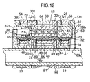
- Fig. 12 shows a second embodiment of the present invention, wherein portions or components corresponding to those in the first embodiment are designated by like reference characters.
- a lubricating oil passage 76 2 is provided in a second support wall 33 2 in a free rocker arm 21 to lead to an oil passage 68 in a rocker shaft 22 and to open toward a needle bearing 55.
- the lubricating oil passage 76 2 comprises a first closed end bore 83 extending in a direction substantially perpendicular to the axis of the rocker shaft 22 with one end closed at a location near the inner surface of the fitting bore 39 2 , and a second bore 84 with one end leading to the first bore 83 at a location near the one closed end of the first bore 83 and with the other end opening toward the needle bearing 55.
- the first bore 83 is formed simultaneously, when the free rocker arm 21 is formed from metal by injection molding.
- the other end of the first bore 83 opens into an outer surface of the free rocker arm 21, but the first bore 83 is put into communication with an oil passage 68 through a communication bore 78 by the rocker shaft 22 being positioned to traverse an intermediate portion of the first bore 83.
- the second bore 84 is made by a drill after the formation of the free rocker arm 21 by injection molding, wherein the axis of the second bore 84 is established, so that an extension of the axis of the second bore 84, i.e., the axis of the drill passing through the fitting bore 39 1 in the support wall 33 1 .
- an extension of the axis of the second bore 84 i.e., the axis of the drill passing through the fitting bore 39 1 in the support wall 33 1 .
- lubricating oil is supplied from the oil passage 68 in the rocker shaft 22 through the lubricating oil passage 76 2 to the needle bearing 55.
- the lubricating oil can be supplied to the needle bearing 55 in a simple structure in which the lubricating oil passage 76 2 is only provided in the second support wall 33 2 included in the free rocker arm 21, and the oil passage structure for supplying oil to the needle bearing can be easily formed, and moreover, it is unnecessary to drill the support shaft 43 for introducing lubricating oil. Therefore, there is not a possibility of reduction in rigidity of the support shaft 43, and further, the number of workings is reduced.
- the lubricating oil passage 76 2 does not open into the fitting bore 39 2 and hence, the entire inner surface of the fitting bore 39 2 can be brought into contact with the outer surface of the support shaft 43, and the supporting area of the support shaft 43 is increased, whereby the supporting rigidity of the support shaft is further enhanced.
- a lubricating oil passage extending rectilinearly to lead to the oil passage 68 in the rocker shaft 22 and to open toward the needle bearing 55, may be provided in an inclined manner in the second support wall 33 2 .
- the present invention is also applicable to a valve operating system for an exhaust valve of an engine valve.
- valve operating system in which the associative operation and the release of the associative operation of the plurality of rocker arms 19, 20 and 21 can be switched over from one to the other by the associative operation switching means 23, has been described in the above embodiments, but the present invention is applicable to a valve operating system in an internal combustion engine, which is designed so that a rocker arm is urged toward a valve operating cam by an urging means, irrespective of the presence or absence of the associative operation switching means.
- rocker arms 19, 20 and 21 are commonly and swingably supported on the rocker shaft 22 in each of the embodiments, but the present invention is applicable to a valve operating system having a structure in which a plurality of rocker arms are swingably supported on ends of separate support columns, respectively.
- the urging means exhibiting the spring force as in the embodiment is used, the arrangement is not complicated, but an urging means exhibiting an urging force by a hydraulic pressure or the like may be used.
Landscapes
- Engineering & Computer Science (AREA)
- Mechanical Engineering (AREA)
- General Engineering & Computer Science (AREA)
- Valve Device For Special Equipments (AREA)
- Valve-Gear Or Valve Arrangements (AREA)
Claims (20)
- Ein Ventilbetätigungssystem in einer Brennkraftmaschine, umfassend eine Nockenwelle (18) versehen mit einer Ventilbetätigungsnocke (26), einen Kipphebel (21), der erste und zweite Tragwände (331, 332) besitzt, die sich in einem Abstand gegenüberliegen, eine Tragwelle (43), die so montiert ist, dass sie zwischen den Tragwänden verläuft, eine Rolle (30), die auf der Tragwelle durch ein Lager (55) drehbar gelagert ist, und ein Vorspannmittel (58), um den Kipphebel in eine Richtung vorzuspannen, um die Rolle in Rollkontakt mit dem Ventilbetätigungsnocken zu bringen, wobei eine (332) der in dem Kipphebel beinhalteten Tragwände mit einem integral eingebauten Aufnahmeabschnitt (62) ausgestattet ist, der mit dem Vorspannmittel (58) Kontakt herstellt,
dadurch gekennzeichnet, dass der Aufnahmeabschnitt (62) und ein die Tragwelle stützender Tragabschnitt der einen (332) der Tragwände in einer gemeinsamen Ebene vorgesehen sind, die sich senkrecht zur Achse der Tragwelle (43) erstreckt. - Ein Ventilbetätigungssystem in einer Brennkraftmaschine nach Anspruch 1, wobei die Nockenwelle (18) mit einer Vielzahl von Ventilbetätigungsnocken (25, 26, 25) ausgestattet ist, mit einer Vielzahl von Kipphebeln (20, 21, 19), die nebeneinander angeordnet sind, und mit einem Koppelbetriebumschaltmittel (23), um zwischen einem Zustand, in dem die benachbarten Kipphebel gekoppelt miteinander betrieben werden und einem Zustand, indem der gekoppelte Betrieb freigegeben ist, umzuschalten und wobei die ersten und zweiten Tragwände (331, 332) an einem freien Hebelarm (21) vorgesehen sind, der in Bezug auf ein Motorventil (V) frei wird, wenn das Koppelbetriebumschaltmittel in den Koppelbetriebfreigabezustand gebracht wird.
- Ein Ventilbetätigungssystem in einer Brennkraftmaschine nach Anspruch 2, wobei in der ersten Tragwand (331) des freien Kipphebels (21) eine erste Passbohrung (391) vorgesehen ist, wobei ein Ende der Tragwelle (43) in die erste Passbohrung eingepasst ist, und wobei in der zweiten Tragwand (332), die den Aufnahmeabschnitt (62) aufweist, eine zweite zur ersten Passbohrung koaxiale Passbohrung (392) vorgesehen ist, wobei das andere Ende der Tragwelle in die zweite Passbohrung eingepasst ist, wobei die erste Tragwand eine Einsetzbohrung (46) hat, die zu einer inneren Fläche der ersten Passbohrung (391) führt, wobei die Tragwelle in einer äußeren Fläche eine Eingreifnut (52), die einer Öffnung der Einsetzbohrung in die innere Fläche der ersten Passbohrung entspricht, und einen Bolzen aufweist, der in die Eingreifnut eingreift, wobei der Bolzen (49) in die Einsetzbohrung eingeführt und eingepasst ist.
- Ein Ventilbetätigungssystem in einer Brennkraftmaschine nach Anspruch 3, wobei die Kipphebel (20, 21, 19) benachbart so zueinander angeordnet sind, dass einer (19) der Kipphebel anders als der freie Kipphebel (21) an einem Ende in Richtung der Anordnung der Kipphebel positioniert ist, und wobei das Koppelbetriebschaltmittel (23) hydraulisch betriebene Kolben (63, 64) umfasst und zwischen dem gekoppelten Betrieb und dem Freigeben des gekoppelten Betriebs der Kipphebel umschaltet als Reaktion auf den Betrieb der Kolben in Folge einer Änderung des hydraulischen Drucks in einer hydraulischen Druckkammer (67), die in dem einen Kipphebel definiert ist, und wobei die Tragwelle eine zylindrische Form hat, um den Kolben (63, 64) gleitend zu führen, und wobei der freie Kipphebel (21) auf einem Stützteil (22) gelagert ist, wobei die erste Tragwand (331) sich auf der Seite des einen Kipphebels (19) befindet.
- Ein Ventilbetätigungssystem in einer Brennkraftmaschine nach Anspruch 2, wobei eine (332) der ersten und zweiten Tragwände (331, 332) des freien Kipphebels (21), der den Aufnahmeabschnitt (62) hat, einen Schmieröldurchlass (761) aufweist, um Schmieröl von einem Öldurchlass (68) in einem Stützteil (22), das den freien Kipphebel (21) bei seiner Kippbewegung stützt, an das Lager (55) des freien Kipphebels zu liefern.
- Ein Ventilbetätigungssystem in einer Brennkraftmaschine nach Anspruch 1, das ein Stützteil (22) aufweist, um den Kipphebel (21) zu lagern, wobei das Stützteil einen Öldurchlass (68) hat; wobei die ersten und zweiten Tragwände (331, 332) Passbohrungen (391, 392) aufweisen, um entgegengesetzte Enden der Tragwelle zu fixieren; wobei der Kipphebel einen Schmieröldurchlass (761) aufweist, der sich in eine innere Oberfläche von wenigstens einer (392) der Passbohrungen in dem Kipphebel öffnet und zum Öldurchlass (68) in dem Stützteil führt; und wobei die wenigstens eine (392) der Passbohrungen eine Nut (77) in ihrer inneren Fläche hat, wobei ein Ende zum Schmieröldurchlass (761) führt und das andere Ende sich in Richtung des Lagers (55) öffnet.
- Ein Ventilbetätigungssystem in einer Brennkraftmaschine nach Anspruch 1, ein Stützteil (22) einschließend um den Kipphebel (21) zu stützen, wobei das Stützteil einen Öldurchlass (68) besitzt, wobei zumindest eine (332) der ersten und zweiten Tragwände (331, 332) einen Schmieröldurchlass (761) umfasst, der zum Öldurchlass (68) in dem Stützteil führt und sich in Richtung des Lagers (55) öffnet.
- Ein Ventilbetätigungssystem in einer Brennkraftmaschine nach Anspruch 1, wobei die Nockenwelle (18) aus einer Vielzahl von Ventilbetätigungsnocken (25, 26, 25) besteht, die zumindest einen Hochgeschwindigkeitsventilbetätigungsnocken (26) umfassen und eine Vielzahl von Kipphebeln (20, 21, 19), die benachbart zueinander angeordnet sind, wobei die Kipphebel einen ersten speziellen Kipphebel (21) umfassen, der operativ mit dem Hochgeschwindigkeitsventilbetätigungsnocken verbunden ist, wobei der Hochgeschwindigkeitsventilbetätigungsnocken ein Nockenprofil besitzt, das die maximale Hubhöhe eines Motorventils (V) zulässt, und ein Koppelbetriebumschaltmittel (23) vorgesehen ist, das Kolben (63, 64) umfasst, die zwischen einer Position, in der die aneinander angrenzend angeordneten Kipphebel gekoppelt miteinander betrieben werden und einer Position, in der dieser gekoppelte Betrieb freigegeben ist, bewegbar sind, wobei die ersten und zweiten Tragwände (331, 332), die zumindest in dem ersten speziellen Kipphebel (21) der Vielzahl von den Kipphebeln vorgesehen sind, Passbohrungen (391, 392) beinhalten, die voneinander getrennt sind und sich koaxial gegenüberliegen, und die Tragwelle (43) eine zylindrische Form hat, um den Kolben gleitend zu führen und entgegen gesetzte Enden hat, die in die Passbohrungen eingepasst und darin fixiert sind, und wobei das System ein Stützteil (22) umfasst, das den ersten speziellen Kipphebel (21) stützt, wobei das Stützteil einen Öldurchlass (68) besitzt und der erste spezielle Kipphebel (21) einen Öldurchlass (761) besitzt, der sich in eine innere Fläche von wenigstens einer (392) der Passbohrungen öffnet und sich zu dem Öldurchlass (68) in dem Stützteil erstreckt, wobei wenigstens eine Passbohrung (392) eine Nut (77) auf ihrer inneren Oberfläche hat, wobei ein Ende zum Schmieröldurchlass (761) führt und das andere Ende sich zum Lager (55) hin öffnet.
- Ein Ventilbetätigungssystem in einer Brennkraftmaschine nach Anspruch 7, wobei der Schmieröldurchlass (761) in einer der Tragwände (332) ist, wobei die andere Tragwand (331) eine Einlassbohrung (46) hat, die sich zu einer inneren Fläche der Passbohrung (392), die in der anderen Tragwand (331) enthalten ist, erstreckt, wobei die Tragwelle (43) eine Eingreifnut (52) hat, die auf ihrer äußeren Oberfläche bereitgestellt ist, die einer Öffnung der Einsetzbohrung (46) in die inneren Fläche der Passbohrung (392) entspricht, und einen Bolzen (49) hat, der in diese Eingreifnut eingreift und in die Einsetzbohrung eingesetzt und in dieser fixiert ist.
- Ein Ventilbetätigungssystem in einer Brennkraftmaschine nach Anspruch 8, wobei in den Kipphebeln (20, 21, 19), die nebeneinander angeordnet sind, einer (19) dieser Kipphebel anders als der erste Kipphebel (21) an einem Ende in Richtung der Anordnung der Kipphebel positioniert ist, wobei der eine Kipphebel (19) eine hydraulische Druckkammer (67) enthält, und die Koppelbetriebumschaltmittel (23) Kolben (63, 64) umfassen, um zwischen dem gekoppelten Betrieb und dem Freigeben des gekoppelten Betriebs der Kipphebel (20, 21, 19) umzuschalten als Reaktion auf den Betrieb der Kolben in Folge einer Änderung des hydraulischen Drucks in der hydraulischen Druckkammer (67), wobei eine Einsetzbohrung (46), die in einer (331) der in dem ersten speziellen dem einen Kipphebel (19) benachbarten Kipphebel (21), vorgesehenen Tragwände vorgesehen ist, wobei die Einsetzbohrung sich bis zu einer inneren Fläche der Passbohrung (391) in der Tragwand (331) erstreckt, wobei die Tragwelle (43) eine Eingreifnut (52) auf ihrer äußeren Oberfläche hat, die einer Öffnung der sich in die Passbohrung öffnenden Einsetzbohrung (46) entspricht, wobei das System einen Bolzen (49) umfasst, der in die Eingreifnut (52) eingreift und in die Einsetzbohrung (46) eingeführt und in dieser fixiert ist, und wobei der Schmieröldurchlass (761) in einer der Tragwände (332) vorgesehen ist, der in einer Position angeordnet ist, die von dem einen Kipphebel (19) abgesetzt ist.
- Ein Ventilbetätigungssystem in einer Brennkraftmaschine nach Anspruch 8, wobei der Schmieröldurchlass (761) eine Querschnittsform mit einer Länge aufweist, die in der im Wesentlichen zur Achse der Nockenwelle (18) senkrechten Richtung länger ist als ihre Länge in der im Wesentlichen zur Achse der Nockenwelle (18) parallelen Richtung.
- Ein Ventilbetätigungssystem in einer Brennkraftmaschine nach Anspruch 6, wobei der Kipphebel (21) aus einem Metall durch Spritzgießen geformt ist.
- Ein Ventilbetätigungssystem in einer Brennkraftmaschine nach Anspruch 1, umfassend eine Vielzahl von den Kipphebeln (20, 21, 19), die benachbart zueinander angeordnet sind, wobei einer (21) der Kipphebel den Aufnahmeabschnitt (62) hat; wobei dieses System ein Koppelbetriebumschaltmittel (23) umfasst mit einem Zeitgeberkolben (63), das eine hydraulische Druckkammer (67) zwischen dem Zeitgeberkolben und einem zweiten speziellen Kipphebel (19) der Kipphebel definiert, wobei das Koppelbetriebumschaltmittel (23) den gekoppelten Betrieb und das Freigeben des gekoppelten Betriebs der Kipphebel schaltet als Reaktion auf den Betrieb des Zeitgeberkolbens (63) infolge einer Änderung des hydraulischen Drucks in der hydraulischen Druckkammer (67), wobei das System ferner ein Stützteil (22) umfasst, um den zweiten speziellen Kipphebel (19) bei Kippbewegungen zu stützen, wobei das Stützteil (22) einen Öldurchlass (68) hat, wobei der zweite spezielle Kipphebel (19) einen Verbindungsdurchgang (70) hat, um den Öldurchlass (68) mit der hydraulischen Druckkammer (67) operativ zu koppeln, wobei der Verbindungsdurchgang eine Querschnittsform hat, die in der Richtung im Wesentlichen senkrecht zur Richtung der Anordnung der Kipphebel, länger ist als in der Richtung im Wesentlichen parallel zur Richtung der Anordnung der Kipphebel, und wobei der Verbindungsdurchgang (70) sich in einer Ebene im Wesentlichen senkrecht zur Richtung der Anordnung der Kipphebel erstreckt.
- Ein Ventilbetätigungssystem in einer Brennkraftmaschine nach Anspruch 13, das weiterhin eine zylindrische Tragwelle (41) umfasst, die an dem zweiten speziellen Kipphebel (19) befestigt ist, wobei der zweite spezielle Kipphebel eine erste Tragwand (311) umfasst, die eine erste Passbohrung (371) mit geschlossenem Ende darin hat und eine zweite Tragwand (312), die eine zweite Passbohrung (372) darin hat, die koaxial mit der ersten Passbohrung ist, und sich an ihren gegenüberliegenden Enden öffnet, wobei die zylindrische Tragwelle (41) an entgegengesetzten Enden in die erste und zweite Passbohrung eingepasst ist und wobei eine Rolle (28) in Rollkontakt mit einer (25) aus einer Vielzahl von Ventilbetätigungsnocken und rollbar auf der zylindrischen Tragwelle (41) gelagert ist, wobei der Zeitgeberkolben (63) frei bewegbar an die zylindrische Tragwelle (41) angepasst ist und wobei der Verbindungsdurchgang (70) in der ersten Tragwand (312) des zweiten speziellen Kipphebels (19) positioniert ist.
- Ein Ventilbetätigungssystem in einer Brennkraftmaschine nach Anspruch 14, wobei die zylindrische Tragwelle (41) eine Aussparung (72) an einem ihrer Enden hat, die dem Verbindungsdurchgang (70) entspricht, wobei die Aussparung eine dem Verbindungsdurchgang entsprechende Form hat.
- Ein Ventilbetätigungssystem in einer Brennkraftmaschine nach Anspruch 14, wobei die zweite Tragwand (312) des zweiten speziellen Kipphebels (19) eine Einführbohrung (44) hat, die zu einer inneren Fläche der zweiten Passbohrung (372) führt; wobei die zylindrische Tragwelle (41) eine Verbindungsnut (50) in ihrer äußeren Oberfläche hat, die einer sich in eine innere Fläche der zweiten Passbohrung (372) öffnenden Öffnung der Einführbohrung (44) entspricht, wobei das System einen Bolzen (47) umfasst, der in die Verbindungsnut (50) eingelassen ist und in die Einführbohrung (44) eingeführt und darin fixiert ist.
- Ein Ventilbetätigungssystem in einer Brennkraftmaschine nach Anspruch 13, wobei der zweite spezielle Kipphebel (19) einen Ausbuchtungsbereich (19b) auf seiner äußeren Fläche an einem Ende in der Richtung der Anordnung der Kipphebel einschließt, wobei der Ausbuchtungsbereich (19b) sich nach außen wölbt, um den Verbindungsdurchgang (70) darin zu definieren und der zweite spezielle Kipphebel (19) eine Rippe (71) auf der äußeren Oberfläche umfasst, die einen Seitenrand (19c) der äußeren Fläche mit dem Ausbuchtungsbereich (19b) verbindet.
- Ein Ventilbetätigungssystem in einer Brennkraftmaschine nach Anspruch 13, wobei der zweite spezielle Kipphebel (19) aus einem Metall durch Spritzgießen geformt ist.
- Ein Ventilbetätigungssystem in einer Brennkraftmaschine nach Anspruch 1, wobei der Kipphebel (21) aus einem Metall durch Spritzgießen geformt ist.
- Ein Ventilbetätigungssystem in einer Brennkraftmaschine nach Anspruch 1, wobei in der einen Tragwand (332) ein Öldurchlass (761) gebildet ist, wobei der Öldurchlass in der gemeinsamen Ebene liegt.
Applications Claiming Priority (9)
| Application Number | Priority Date | Filing Date | Title |
|---|---|---|---|
| JP167235/97 | 1997-06-24 | ||
| JP16723597 | 1997-06-24 | ||
| JP16723597A JP3319980B2 (ja) | 1997-06-24 | 1997-06-24 | 内燃機関の動弁装置 |
| JP16830497 | 1997-06-25 | ||
| JP16830497A JP3319981B2 (ja) | 1997-06-25 | 1997-06-25 | 内燃機関の動弁装置 |
| JP168304/97 | 1997-06-25 | ||
| JP171852/97 | 1997-06-27 | ||
| JP17185297 | 1997-06-27 | ||
| JP17185297A JP3319982B2 (ja) | 1997-06-27 | 1997-06-27 | 内燃機関の動弁装置 |
Publications (2)
| Publication Number | Publication Date |
|---|---|
| EP0887519A1 EP0887519A1 (de) | 1998-12-30 |
| EP0887519B1 true EP0887519B1 (de) | 2003-07-09 |
Family
ID=27322826
Family Applications (1)
| Application Number | Title | Priority Date | Filing Date |
|---|---|---|---|
| EP98111557A Expired - Lifetime EP0887519B1 (de) | 1997-06-24 | 1998-06-23 | Ventilsteuerungseinrichtung für eine Brennkraftmaschine |
Country Status (5)
| Country | Link |
|---|---|
| US (2) | US5979379A (de) |
| EP (1) | EP0887519B1 (de) |
| CN (1) | CN1106497C (de) |
| DE (1) | DE69816187T2 (de) |
| TW (1) | TW387033B (de) |
Families Citing this family (27)
| Publication number | Priority date | Publication date | Assignee | Title |
|---|---|---|---|---|
| US6412460B1 (en) | 1997-06-24 | 2002-07-02 | Honda Giken Kogyo Kabushiki Kaisha | Valve operating system in internal combustion engine |
| DE69926475T2 (de) * | 1998-12-22 | 2006-04-06 | Honda Giken Kogyo K.K. | Ventilsteuerungseinrichtung für eine Brennkraftmaschine |
| JP3535421B2 (ja) * | 1998-12-22 | 2004-06-07 | 本田技研工業株式会社 | 内燃機関の動弁装置 |
| TW475961B (en) | 1999-12-27 | 2002-02-11 | Honda Motor Co Ltd | Valve operating system in internal combustion engine |
| JP3523133B2 (ja) * | 1999-12-27 | 2004-04-26 | 本田技研工業株式会社 | 内燃機関の動弁装置 |
| JP3535431B2 (ja) * | 1999-12-28 | 2004-06-07 | 本田技研工業株式会社 | 内燃機関の動弁装置 |
| JP4310016B2 (ja) * | 2000-01-18 | 2009-08-05 | 本田技研工業株式会社 | 内燃機関の動弁装置 |
| US6273040B1 (en) | 2000-05-04 | 2001-08-14 | William P. Curtis | Adjustable overhead rocker cam |
| JP3843207B2 (ja) * | 2000-10-04 | 2006-11-08 | 田中精密工業株式会社 | 内燃機関の動弁装置 |
| US6532920B1 (en) | 2002-02-08 | 2003-03-18 | Ford Global Technologies, Inc. | Multipositional lift rocker arm assembly |
| CN100417787C (zh) * | 2003-12-18 | 2008-09-10 | 丰田自动车株式会社 | 可变气门机构 |
| JP4008411B2 (ja) * | 2003-12-24 | 2007-11-14 | 本田技研工業株式会社 | 内燃機関のバルブリフト可変装置 |
| CN100396891C (zh) * | 2004-01-16 | 2008-06-25 | 本田技研工业株式会社 | 发动机的气门传动装置 |
| CN100427728C (zh) * | 2004-01-16 | 2008-10-22 | 本田技研工业株式会社 | 发动机的气门传动装置 |
| CN100396892C (zh) * | 2004-01-30 | 2008-06-25 | 本田技研工业株式会社 | 发动机 |
| DE102004028221A1 (de) * | 2004-06-09 | 2005-12-29 | Ina-Schaeffler Kg | Hochbeanspruchtes Motorenbauteil |
| JP4026634B2 (ja) * | 2004-08-31 | 2007-12-26 | トヨタ自動車株式会社 | 可変動弁装置 |
| DE602005025368D1 (de) * | 2004-08-31 | 2011-01-27 | Toyota Motor Co Ltd | Verstellbare ventilsteuerung |
| US7530338B2 (en) * | 2005-04-26 | 2009-05-12 | Chrysler Llc | Valvetrain system for an engine |
| US7415954B2 (en) * | 2005-04-26 | 2008-08-26 | Chrysler Llc | Rocker shaft arrangement for an engine |
| US9790824B2 (en) | 2010-07-27 | 2017-10-17 | Jacobs Vehicle Systems, Inc. | Lost motion valve actuation systems with locking elements including wedge locking elements |
| JP6030058B2 (ja) | 2010-07-27 | 2016-11-24 | ジェイコブス ビークル システムズ、インコーポレイテッド | エンジン・ブレーキと正出力エンジン併用の空動きバルブ作動システム |
| US20140251266A1 (en) * | 2011-07-27 | 2014-09-11 | Jacobs Vehicle Systems, Inc. | Auxiliary Valve Motions Employing Disablement of Main Valve Events and/or Coupling of Adjacent Rocker Arms |
| EP2607636B1 (de) * | 2011-12-23 | 2015-10-14 | Aktiebolaget SKF | Mechanisches System, Einspritzpumpe mit solch einem mechanischen System und Verfahren zur Herstellung solch eines mechanischen Systems |
| EP2653673A1 (de) * | 2012-04-19 | 2013-10-23 | Eaton S.r.l. | Schaltbarer Kipphebel |
| GB201211534D0 (en) * | 2012-06-29 | 2012-08-08 | Eaton Srl | Valve bridge |
| US10876436B2 (en) | 2016-10-07 | 2020-12-29 | Eaton Intelligent Power Limited | Three roller rocker arm with cantilevered rollers and lost motion spring over valve or over rocker arm pivot |
Family Cites Families (9)
| Publication number | Priority date | Publication date | Assignee | Title |
|---|---|---|---|---|
| JPS63100211A (ja) * | 1986-10-15 | 1988-05-02 | Honda Motor Co Ltd | 内燃機関の動弁装置 |
| JPH0250286A (ja) | 1988-08-12 | 1990-02-20 | Toshiba Corp | 携帯可能電子装置 |
| EP0588336B1 (de) * | 1992-09-16 | 1995-12-27 | Honda Giken Kogyo Kabushiki Kaisha | Ventiltriebanordnung für eine Brennkraftmaschine |
| JP3319794B2 (ja) * | 1993-01-18 | 2002-09-03 | 本田技研工業株式会社 | 内燃機関のsohc型動弁装置 |
| JP2762213B2 (ja) * | 1993-08-18 | 1998-06-04 | 本田技研工業株式会社 | 内燃機関の動弁装置 |
| DE9406190U1 (de) * | 1994-04-14 | 1994-06-09 | INA Wälzlager Schaeffler KG, 91074 Herzogenaurach | Vorrichtung zur gleichzeitigen Betätigung von zumindest zwei Gaswechselventilen |
| JP3253045B2 (ja) * | 1994-08-25 | 2002-02-04 | 本田技研工業株式会社 | 多気筒内燃機関の動弁装置 |
| DE4433457C2 (de) * | 1994-09-20 | 2003-03-06 | Bayerische Motoren Werke Ag | Brennkraftmaschine mit koppelbaren Ventilbetätigungselementen |
| JP3547912B2 (ja) * | 1996-08-29 | 2004-07-28 | 本田技研工業株式会社 | 内燃機関の動弁装置 |
-
1998
- 1998-06-22 TW TW087109994A patent/TW387033B/zh not_active IP Right Cessation
- 1998-06-23 EP EP98111557A patent/EP0887519B1/de not_active Expired - Lifetime
- 1998-06-23 DE DE69816187T patent/DE69816187T2/de not_active Expired - Lifetime
- 1998-06-23 US US09/102,630 patent/US5979379A/en not_active Expired - Lifetime
- 1998-06-24 CN CN98115073A patent/CN1106497C/zh not_active Expired - Fee Related
-
1999
- 1999-10-19 US US09/420,409 patent/US6125805A/en not_active Expired - Lifetime
Also Published As
| Publication number | Publication date |
|---|---|
| US6125805A (en) | 2000-10-03 |
| DE69816187T2 (de) | 2004-05-27 |
| CN1203309A (zh) | 1998-12-30 |
| CN1106497C (zh) | 2003-04-23 |
| DE69816187D1 (de) | 2003-08-14 |
| TW387033B (en) | 2000-04-11 |
| US5979379A (en) | 1999-11-09 |
| EP0887519A1 (de) | 1998-12-30 |
Similar Documents
| Publication | Publication Date | Title |
|---|---|---|
| US5979379A (en) | Valve operating system in internal combustion engine | |
| US4848285A (en) | Valve operating apparatus for an internal combustion engine | |
| EP1113151B1 (de) | Ventilsteuerungseinrichtung in einer Brennkraftmaschine | |
| US4612884A (en) | Valve operating and interrupting mechanism for internal combustion engine | |
| KR960007963B1 (ko) | 내연기관용 밸브제어수단 | |
| US5127374A (en) | Valve lifter | |
| JPH068604B2 (ja) | 内燃機関の弁作動状態切換装置 | |
| US6186102B1 (en) | Valve operating system for internal combustion engine | |
| US5178107A (en) | Valve lifter | |
| US6412460B1 (en) | Valve operating system in internal combustion engine | |
| US6854432B2 (en) | Valve gear of internal combustion engine | |
| US6067947A (en) | Valve driving apparatus for engine | |
| EP0843078A1 (de) | Ventilsteuerungsvorrichtung in einer Brennkraftmaschine | |
| US6467444B2 (en) | Valve operating system in internal combustion engine | |
| EP1113148B1 (de) | Ventilsteuerungseinrichtung in einer Brennkraftmaschine | |
| JP3319980B2 (ja) | 内燃機関の動弁装置 | |
| JP3319981B2 (ja) | 内燃機関の動弁装置 | |
| EP1013898B1 (de) | Ventilsteuerungseinrichtung für eine Brennkraftmaschine | |
| JP3319982B2 (ja) | 内燃機関の動弁装置 | |
| JPH04325705A (ja) | エンジンの弁作動装置 | |
| JP3542294B2 (ja) | 内燃機関の動弁装置 | |
| JPH02223613A (ja) | 内燃機関における動弁装置 | |
| JP3320046B2 (ja) | 内燃機関の動弁装置 | |
| US6067948A (en) | Device for actuating at least one gas exchange valve of an internal combustion engine | |
| JPH01300005A (ja) | 動弁機構用カム軸の加工方法 |
Legal Events
| Date | Code | Title | Description |
|---|---|---|---|
| PUAI | Public reference made under article 153(3) epc to a published international application that has entered the european phase |
Free format text: ORIGINAL CODE: 0009012 |
|
| AK | Designated contracting states |
Kind code of ref document: A1 Designated state(s): DE FR |
|
| AX | Request for extension of the european patent |
Free format text: AL;LT;LV;MK;RO;SI |
|
| 17P | Request for examination filed |
Effective date: 19990624 |
|
| AKX | Designation fees paid |
Free format text: DE FR |
|
| GRAH | Despatch of communication of intention to grant a patent |
Free format text: ORIGINAL CODE: EPIDOS IGRA |
|
| GRAH | Despatch of communication of intention to grant a patent |
Free format text: ORIGINAL CODE: EPIDOS IGRA |
|
| GRAA | (expected) grant |
Free format text: ORIGINAL CODE: 0009210 |
|
| RIN1 | Information on inventor provided before grant (corrected) |
Inventor name: OTOBE, YUTAKA Inventor name: OIKAWA, TOSHIHIRO Inventor name: SATO, TOSHIYUKI |
|
| AK | Designated contracting states |
Designated state(s): DE FR |
|
| REF | Corresponds to: |
Ref document number: 69816187 Country of ref document: DE Date of ref document: 20030814 Kind code of ref document: P |
|
| ET | Fr: translation filed | ||
| PLBE | No opposition filed within time limit |
Free format text: ORIGINAL CODE: 0009261 |
|
| STAA | Information on the status of an ep patent application or granted ep patent |
Free format text: STATUS: NO OPPOSITION FILED WITHIN TIME LIMIT |
|
| 26N | No opposition filed |
Effective date: 20040414 |
|
| PGFP | Annual fee paid to national office [announced via postgrant information from national office to epo] |
Ref country code: FR Payment date: 20080617 Year of fee payment: 11 |
|
| REG | Reference to a national code |
Ref country code: FR Ref legal event code: ST Effective date: 20100226 |
|
| PG25 | Lapsed in a contracting state [announced via postgrant information from national office to epo] |
Ref country code: FR Free format text: LAPSE BECAUSE OF NON-PAYMENT OF DUE FEES Effective date: 20090630 |
|
| REG | Reference to a national code |
Ref country code: DE Ref legal event code: R084 Ref document number: 69816187 Country of ref document: DE Effective date: 20120209 |
|
| PGFP | Annual fee paid to national office [announced via postgrant information from national office to epo] |
Ref country code: DE Payment date: 20120620 Year of fee payment: 15 |
|
| REG | Reference to a national code |
Ref country code: DE Ref legal event code: R119 Ref document number: 69816187 Country of ref document: DE Effective date: 20140101 |
|
| PG25 | Lapsed in a contracting state [announced via postgrant information from national office to epo] |
Ref country code: DE Free format text: LAPSE BECAUSE OF NON-PAYMENT OF DUE FEES Effective date: 20140101 |