EP0887581B1 - Schieber für ein erodierendes Strömungssystem - Google Patents
Schieber für ein erodierendes Strömungssystem Download PDFInfo
- Publication number
- EP0887581B1 EP0887581B1 EP98111856A EP98111856A EP0887581B1 EP 0887581 B1 EP0887581 B1 EP 0887581B1 EP 98111856 A EP98111856 A EP 98111856A EP 98111856 A EP98111856 A EP 98111856A EP 0887581 B1 EP0887581 B1 EP 0887581B1
- Authority
- EP
- European Patent Office
- Prior art keywords
- valve
- valve member
- stationary
- flow passage
- slide valve
- Prior art date
- Legal status (The legal status is an assumption and is not a legal conclusion. Google has not performed a legal analysis and makes no representation as to the accuracy of the status listed.)
- Expired - Lifetime
Links
- 230000003628 erosive effect Effects 0.000 title claims description 10
- 239000012530 fluid Substances 0.000 claims abstract description 25
- 238000010926 purge Methods 0.000 claims abstract description 15
- 238000011144 upstream manufacturing Methods 0.000 claims abstract 3
- 239000011819 refractory material Substances 0.000 claims description 17
- 239000002245 particle Substances 0.000 claims description 9
- 239000000463 material Substances 0.000 claims description 8
- 239000007769 metal material Substances 0.000 claims description 4
- 238000004140 cleaning Methods 0.000 claims 1
- 230000004048 modification Effects 0.000 abstract 1
- 238000012986 modification Methods 0.000 abstract 1
- 230000001681 protective effect Effects 0.000 abstract 1
- 230000000717 retained effect Effects 0.000 abstract 1
- UQSXHKLRYXJYBZ-UHFFFAOYSA-N Iron oxide Chemical compound [Fe]=O UQSXHKLRYXJYBZ-UHFFFAOYSA-N 0.000 description 12
- XEEYBQQBJWHFJM-UHFFFAOYSA-N Iron Chemical compound [Fe] XEEYBQQBJWHFJM-UHFFFAOYSA-N 0.000 description 11
- 239000007789 gas Substances 0.000 description 9
- 230000008878 coupling Effects 0.000 description 5
- 238000010168 coupling process Methods 0.000 description 5
- 238000005859 coupling reaction Methods 0.000 description 5
- 229910052742 iron Inorganic materials 0.000 description 5
- 230000009467 reduction Effects 0.000 description 5
- 229910044991 metal oxide Inorganic materials 0.000 description 4
- 150000004706 metal oxides Chemical class 0.000 description 4
- 239000010935 stainless steel Substances 0.000 description 4
- 229910001220 stainless steel Inorganic materials 0.000 description 4
- CURLTUGMZLYLDI-UHFFFAOYSA-N Carbon dioxide Chemical compound O=C=O CURLTUGMZLYLDI-UHFFFAOYSA-N 0.000 description 3
- VNWKTOKETHGBQD-UHFFFAOYSA-N methane Chemical compound C VNWKTOKETHGBQD-UHFFFAOYSA-N 0.000 description 3
- 239000007787 solid Substances 0.000 description 3
- 229910002092 carbon dioxide Inorganic materials 0.000 description 2
- 229910002091 carbon monoxide Inorganic materials 0.000 description 2
- 230000007812 deficiency Effects 0.000 description 2
- 238000000034 method Methods 0.000 description 2
- 230000008569 process Effects 0.000 description 2
- 230000008439 repair process Effects 0.000 description 2
- 238000003466 welding Methods 0.000 description 2
- IJGRMHOSHXDMSA-UHFFFAOYSA-N Atomic nitrogen Chemical compound N#N IJGRMHOSHXDMSA-UHFFFAOYSA-N 0.000 description 1
- UGFAIRIUMAVXCW-UHFFFAOYSA-N Carbon monoxide Chemical compound [O+]#[C-] UGFAIRIUMAVXCW-UHFFFAOYSA-N 0.000 description 1
- 229910000975 Carbon steel Inorganic materials 0.000 description 1
- UFHFLCQGNIYNRP-UHFFFAOYSA-N Hydrogen Chemical compound [H][H] UFHFLCQGNIYNRP-UHFFFAOYSA-N 0.000 description 1
- 230000009471 action Effects 0.000 description 1
- 239000000853 adhesive Substances 0.000 description 1
- 230000001070 adhesive effect Effects 0.000 description 1
- 230000000903 blocking effect Effects 0.000 description 1
- 239000001569 carbon dioxide Substances 0.000 description 1
- 239000010962 carbon steel Substances 0.000 description 1
- 238000005266 casting Methods 0.000 description 1
- 230000008859 change Effects 0.000 description 1
- 230000005465 channeling Effects 0.000 description 1
- 238000005520 cutting process Methods 0.000 description 1
- 230000001419 dependent effect Effects 0.000 description 1
- 238000011161 development Methods 0.000 description 1
- 230000018109 developmental process Effects 0.000 description 1
- 239000001257 hydrogen Substances 0.000 description 1
- 229910052739 hydrogen Inorganic materials 0.000 description 1
- 239000011261 inert gas Substances 0.000 description 1
- 239000011810 insulating material Substances 0.000 description 1
- 239000000203 mixture Substances 0.000 description 1
- 238000009877 rendering Methods 0.000 description 1
Images


Classifications
-
- F—MECHANICAL ENGINEERING; LIGHTING; HEATING; WEAPONS; BLASTING
- F16—ENGINEERING ELEMENTS AND UNITS; GENERAL MEASURES FOR PRODUCING AND MAINTAINING EFFECTIVE FUNCTIONING OF MACHINES OR INSTALLATIONS; THERMAL INSULATION IN GENERAL
- F16K—VALVES; TAPS; COCKS; ACTUATING-FLOATS; DEVICES FOR VENTING OR AERATING
- F16K3/00—Gate valves or sliding valves, i.e. cut-off apparatus with closing members having a sliding movement along the seat for opening and closing
- F16K3/02—Gate valves or sliding valves, i.e. cut-off apparatus with closing members having a sliding movement along the seat for opening and closing with flat sealing faces; Packings therefor
- F16K3/0218—Gate valves or sliding valves, i.e. cut-off apparatus with closing members having a sliding movement along the seat for opening and closing with flat sealing faces; Packings therefor with only one sealing face
-
- B—PERFORMING OPERATIONS; TRANSPORTING
- B22—CASTING; POWDER METALLURGY
- B22D—CASTING OF METALS; CASTING OF OTHER SUBSTANCES BY THE SAME PROCESSES OR DEVICES
- B22D41/00—Casting melt-holding vessels, e.g. ladles, tundishes, cups or the like
- B22D41/14—Closures
- B22D41/22—Closures sliding-gate type, i.e. having a fixed plate and a movable plate in sliding contact with each other for selective registry of their openings
-
- Y—GENERAL TAGGING OF NEW TECHNOLOGICAL DEVELOPMENTS; GENERAL TAGGING OF CROSS-SECTIONAL TECHNOLOGIES SPANNING OVER SEVERAL SECTIONS OF THE IPC; TECHNICAL SUBJECTS COVERED BY FORMER USPC CROSS-REFERENCE ART COLLECTIONS [XRACs] AND DIGESTS
- Y10—TECHNICAL SUBJECTS COVERED BY FORMER USPC
- Y10T—TECHNICAL SUBJECTS COVERED BY FORMER US CLASSIFICATION
- Y10T137/00—Fluid handling
- Y10T137/4238—With cleaner, lubrication added to fluid or liquid sealing at valve interface
- Y10T137/4245—Cleaning or steam sterilizing
- Y10T137/4259—With separate material addition
-
- Y—GENERAL TAGGING OF NEW TECHNOLOGICAL DEVELOPMENTS; GENERAL TAGGING OF CROSS-SECTIONAL TECHNOLOGIES SPANNING OVER SEVERAL SECTIONS OF THE IPC; TECHNICAL SUBJECTS COVERED BY FORMER USPC CROSS-REFERENCE ART COLLECTIONS [XRACs] AND DIGESTS
- Y10—TECHNICAL SUBJECTS COVERED BY FORMER USPC
- Y10T—TECHNICAL SUBJECTS COVERED BY FORMER US CLASSIFICATION
- Y10T137/00—Fluid handling
- Y10T137/6851—With casing, support, protector or static constructional installations
- Y10T137/7036—Jacketed
Definitions
- the present invention relates to a slide valve which can operate in high pressure, high temperature, erosive flow systems.
- the slide valve of the present invention has particular utility in equipment for the direct reduction of metal oxides containing iron to obtain a DRI metallized iron product.
- Slide valves have been utilized in equipment for the direct reduction of metal oxides containing iron. These slide valves include two movable valve members with each valve member having an orifice that defines a portion of the material flow path when the valve is in an open position.
- the slide valve is typically surrounded by a refractory type insulating material.
- These slide valves have suffered from a number of deficiencies as a result of the environment in which they are employed. The high pressure and temperatures in the environment cause iron oxide particles in the flow stream to fluidize. These fluidized particles, travelling at high speed, impinge upon and adhere to surfaces of the valve elements. Eventually, the particles build up to a point where the two valve members become friction welded and inoperative. Additionally, the slide valves have suffered from the deficiency that the material flowing through the system at high pressure, temperature and speed tends to channel through the refractory material. Eventually, a path around the slide valve is created.
- FIG. 1 Another slide valve arrangement, which is utilized in a similar environment, is shown in U.S. Patent No. 3,964,507 to Jandrasi et al.
- This arrangement includes a slide valve and a disc-like valve member having a valve surface or seat. Sliding movement of the slide valve across the valve surface of the valve member opens and closes the flow passage extending through the valve body.
- the valve arrangement is secured in place by a complex structure which includes an annular body in the form of a truncated cone.
- the Jandrasi et al. Type of slide valve has experienced operating problems in those environments where there is a high pressure change across the valve. The valve was not designed to cycle in high pressure environments.
- US 5,626,164 discloses a slide valve showing the features of the preamble of claim 1.
- the movable valve member has an orifice therein and is movable between a first position wherein said orifice is aligned with the flow passage and a second position wherein said orifice is non-aligned with the flow passage.
- FIG. 1 illustrates a slide valve 10 suitable for use in a high pressure, high temperature, erosive flow system environment, such as in equipment for the direct reduction of metal oxides containing iron wherein a flow medium containing fluidized iron oxide particles travels at relatively high speeds.
- the slide valve 10 is incorporated into a pipeline, conduit, or some other piece of equipment defining a portion of the flow path for said flow medium.
- the slide valve 10 includes a housing 12, which may be formed from a low cost, low temperature material such as carbon steel.
- the housing 12 may be joined to the pipeline, conduit or other equipment using any suitable means known in the art.
- a castable, insulating refractory liner material 14 such as Resco RA-22 is used to line the housing 12. As shown in FIG. 1, the refractory material 14 is formed, preferably by casting, to have a central bore 16 which defines a fluid passageway 18.
- the slide valve 10 further includes a stationary valve member 20 and a movable valve member 22.
- the valve members 20 and 22 may be formed from any suitable material known in the art. Preferably, they are formed from a material such as stainless steel.
- Each of the valve members 20 and 22 is provided with an opening 24 and 26, respectively. When the slide valve 10 is in a fully open position, the openings 24 and 26 are aligned with each other and the fluid passageway 18. Details on how the movable valve member 22 slides relative to the stationary member 20 will be discussed hereinbelow.
- the slide valve 10 further includes a tube 28 and a plate 30.
- the tube 28 is preferably formed from a metallic material, such as a stainless steel, and serves to substantially prevent the medium flowing through the fluid passageway 18 from creating a channel around the valve members 20 and 22.
- a metallic material such as a stainless steel
- the prior art valves became inoperative due to channels in the refractory material which allow the medium to flow around the valve members.
- the tube 28 is inset in a recess in the refractory material 14.
- the inner wall 29 of the tube 28 is aligned with the wall 31 of the refractory material 14 which defines the fluid passageway 18.
- the plate 30 is also formed from a metallic material, such as stainless steel. It too resides in a recess in the refractory material 14 and is provided to substantially prevent channelling around the valve members 20 and 22.
- the plate 30 is preferably joined to the tube 28 such as by welding. If desired, the plate 30 may also be joined to the refractory material 14 using suitable means known in the art such as an adhesive.
- the plate 30 is also joined to the stationary valve member 20 such as by welding. As shown in FIG. 1, the plate 30 has an opening 32 which is aligned with the fluid passageway 18 and the opening 24 at all times and with the opening 26 when the valve is in an open position.
- the movable valve member 22 travels in a transverse direction relative to the path of the flow medium through the passageway 18. Any suitable means may be provided to guide the valve member 22.
- the valve member 22 may travel along rails 34 and 36 defined by L-shaped supports 38 and 40 incorporated into the housing 12. Any suitable means known in the art may be used to move the valve member 22 along the rails 34 and 36.
- an air piston type operator 50 with air on both sides of the piston is used to move the valve member 22 between its various positions. Using an air piston type operator, it is possible to move the valve member 22 so that it partially or completely restricts or blocks flow through the valve 10.
- the movable valve member 22 When the valve 10 is in a fully closed position, the movable valve member 22 is positioned relative to the stationary valve member 20 so that the opening 24 in the stationary valve member 20 is covered by a solid portion of the movable valve member 22. In other words, in the valve fully closed position, the openings 24 and 26 are no longer aligned with each other. In a partially closed position, the valve member 22 is positioned relative to the stationary valve member 20 so that a solid portion of the movable valve member 22 partially covers a portion of the opening 24 in the stationary valve member 20.
- valve member 22 As previously discussed, it is desired to move the valve member 22 using an air piston type operator 50. Using such an arrangement, a valve such as that of the present invention will travel full stroke in 4-5 seconds.
- the operating air used in the piston may be dry air at a pressure of about 6.5 bar.
- the air is piped to the cylinder surrounding the piston during normal operation through a valve 52 whose position is set by means of a hand control indicator 54 to enable it to cycle from full open to part open.
- the hand control indicator At a typically full capacity for a DRI reduction system in which the slide valve 10 is incorporated, the hand control indicator is set at about 50% opening.
- the open/close time is set by means of a timer 56 to enable the valve to be cycled.
- the timer 56 has a 60 second dial range with a minimum setting of 1 second.
- the dial preferably has two time scales including an outer scale for the "off” time and an inner scale for the "on” time.
- Each time scale has a dial pointer and knob for setting the exact "on” and "off” time desired.
- the timer 56 can be adjusted any time during the time cycle and can immediately pick up a new time setting.
- the timer 56 can be energized manually or can receive a signal from an outside source such as a level controller (not shown).
- the slide valve 10 of the present invention can operate in the following manner. When there is no power to the timer 56, the slide valve 10 is closed. When power is provided to the timer 56 and there is no signal from the level controller (not shown), the valve 10 will cycle in accordance with the timer setting from open to part open depending on the value set in the hand control indicator 54. During normal operation, on level control, the valve 10 will cycle when the level in the reactor is above the set point of the level controller in accordance with the settings in the timer 56 and the hand control indicator 54. In the case of the failure of the valve positioning system, a back-up system is provided.
- the air to the piston 50 is piped through solenoid valves (not shown) so that when the solenoids are energized, the valve 10 will travel full stroke.
- the timer 56 can be adjusted in order to limit the valve 10 from full open to part open if required.
- valve 10 When used in a system for the direct reduction of metal oxides containing iron, there typically is a high pressure differential across the valve members 20 and 22. At the inlet of the valve 10, typically one encounters a pressure of 160 psi. At the outlet of the valve 10, the pressure is typically about 14 psi. Additionally, the valve 10 must operate at an elevated temperature, typically about 1450°F. The medium which is transported through the valve 10 in this environment often includes iron oxide particles travelling at a high speed. Due to the elevated temperature and the high flow speed, the iron oxide particles become fluidized. As a result, these fluidized iron oxide particles impinge upon and adhere to the opposed valve member surfaces- 42 and 44 as well as other surfaces of the valve members 20 and 22.
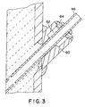
- the slide valve 10 includes two fluid conduits 46 and 48.
- the fluid conduits 46 and 48 are aligned at an angle with respect to the direction A of flow of the medium though the fluid passageway 18.
- Each of the fluid conduits 46 and 48 is formed by a metallic tube such as a stainless steel tube.
- Surrounding a portion of each tube is a coupling 60.
- the coupling 60 is used to mount the fluid conduits 46 and 48 to the housing 12. If desired, each coupling 60 may be welded to the housing 12.
- the coupling 60 is provided with a bore 62 and a stopper 64.
- bore 62 The function of bore 62 is as follows. When the fluid conduit 46 gets plugged beyond repair, it must be removed. This is done by cutting the weld between the stopper 64 and the coupling 60. The bore 62 helps in conduit removal by providing room to shake the conduit out. This action is sometimes necessary due to deformation in the shape of the conduit 46 by the hot fluid inside. The stopper 64 is needed to fix the conduit to the valve body and at the same time allows for thermal expansion of the conduit.
- the fluid conduits 46 and 48 serve several purposes. First, they allow unwanted gases to be purged from the fluid passageway 18. Furthermore, the fluid conduits may be used to introduce high pressure purge gas into the fluid passageway 18.
- the high pressure purge gas is used to remove any fluidized iron oxide particles, as well as other debris, from the opposed surfaces 42 and 44 and other surfaces of the valve components during operation of the plant.
- the pressurized purge gas is introduced into the fluid passageway in two different, opposed directions via the fluid conduits.
- the purge gas may be any suitable gas which is compatible with the solids of the process being carried out in the reactor. The gas is used to clean and to drain.
- the purge gas is a mixture of hydrogen (up to 91% H 2 ), carbon dioxide (up to 1% CO 2 ), methane (up to 5% CH 4 ) and carbon monoxide (up to 5% CO) or inert gas such as Nitrogen (N 2 ).
- the slide valve 10 of the present invention is most advantageous. It is rather easy to assemble since there are a minimal number of parts. Similarly, it is easy to disassemble if repairs are required. Additionally, the valve is relatively inexpensive to produce and to install. Most significantly, the valve operates smoothly in a high pressure, high temperature, erosive flow environment.
Landscapes
- Engineering & Computer Science (AREA)
- General Engineering & Computer Science (AREA)
- Mechanical Engineering (AREA)
- Sliding Valves (AREA)
- Electrical Discharge Machining, Electrochemical Machining, And Combined Machining (AREA)
- Paper (AREA)
- Magnetic Bearings And Hydrostatic Bearings (AREA)
- Casting Support Devices, Ladles, And Melt Control Thereby (AREA)
Claims (14)
- Schieber (10) zur Verwendung in einem erodierenden Strömungssystem unter hohem Druck und hoher Temperatur, bestehend aus:einem Schiebergehäuse (12);einem Mittel zur Bildung eines Strömungsdurchgangs für ein Medium innerhalb des Schiebergehäuses (12);einem bezüglich des Strömungsdurchgangs feststehenden Schieberglied (20); undeinem bezüglich des Strömungsdurchgang beweglichen Schieberglied (22) zur Steuerung der Strömung durch den Strömungsdurchgang, wobei das bewegliche Schieberglied (22) eine darin ausgebildete Öffnung aufweist und zwischen einer ersten Position, in der die Öffnung nach dem Strömungsdurchgang ausgerichtet ist, und einer zweiten Position, in der die Öffnung nicht nach dem Strömungsdurchgang ausgerichtet ist und das feststehende Schieberglied (20) eine nach dem Strömungsdurchgang ausgerichtete Öffnung (24) aufweist, beweglich ist,gekennzeichnet durch ein feststehendes Schieberglied, welches ein Mittel zum Einführen eines strömenden Mediums in den Strömungsdurchgang zum Reinigen der Oberflächen dieses feststehenden Schieberglieds (20) und des beweglichen Schieberglieds (22) aufweist.
- Schieber (10) nach Anspruch 1, in welchem das den Strömungsdurchgang bildende Mittel eine Zwischenlage aus feuerfestem Material (14) innerhalb des Schiebergehäuses (12) umfaßt.
- Schieber (10) nach Anspruch 1 oder 2, ferner bestehend aus: einer am feststehenden Schieberglied (20) befestigten Platte (30) zur weitgehenden Vermeidung einer Kanalbildung um das feststehende Schieberglied (20) herum; einer ersten Vertiefung im feuerfesten Material (14); und der in dieser Vertiefung angeordneten Platte.
- Schieber (10) nach einem der Ansprüche 1 bis 3, ferner bestehend aus: einem im feuerfesten Material (14) eingebetteten Rohr (28) zur weitgehenden Vermeidung einer Kanalbildung durch das feuerfeste Material (14) hindurch; einer Innenwand (29) dieses Rohres (28), die einen Abschnitt des Strömungsdurchgangs bildet und nach einer Wand des den Strömungsdurchgang begrenzenden feuerfesten Materials (31) ausgerichtet ist; und der mit dem Rohr (28) verbundenen Platte (30).
- Schieber (10) nach einem der Ansprüche 3 bis 4, ferner bestehend aus: der aus einem metallischen Material gebildeten Platte (30); dem aus einem metallischen Material gebildeten Rohr (28); und der an das Rohr (28) geschweißten Platte (30).
- Schieber (10) nach einem der Ansprüche 1 bis 5, in welchem das Mittel zum Einführen des strömenden Mediums umfaßt: einen ersten, bezüglich des feststehenden Schieberglieds stromaufwärts angeordneten Kanal (46) zum Einführen eines Spülgases unter Druck in den Strömungsdurchgang, so dass das Spülgas in eine erste Richtung fließt; und einen zweiten, stromabwärts zum feststehenden Schieberglied angeordneten Kanal (48) zum Einführen eines Spülgases unter Druck in den Strömungsdurchgang, so dass das Spülgas in eine zweite, zur ersten entgegengesetzte Richtung strömt, wobei das unter Druck stehende Spülgas in den Strömungsdurchgang durch den ersten (46) und zweiten Kanal (48) in eine Spalte zwischen dem feststehenden (20) und dem beweglichen Schieberglied (22) eingeführt wird, so dass fluidisierte Partikel und andere Ablagerungen von diesen entfernt werden und hierdurch ein Reibverschweißen des feststehenden Schieberglieds (20) mit dem beweglichen Schieberglied (22) verhindert wird.
- Schieber (10) nach einem der Ansprüche 1 bis 6, ferner bestehend aus: einem Mittel zum gesteuerten Verfahren des beweglichen Schieberglieds (22) bezogen auf das feststehende Schieberglied (20).
- Schieber (10) nach einem der Ansprüche 1 bis 7, ferner bestehend aus: einem Mittel zum Verfahren des beweglichen Schieberglieds (22) zwischen einer ersten und einer zweiten Position.
- Schieber (10) zur Verwendung in einem erodierenden Strömungssystem unter hohem Druck und hoher Temperatur, bestehend aus:einem Gehäuse (12);einer aus einem feuerfesten Material in dem Gehäuse gebildeten Zwischenlage;wobei die Zwischenlage eine Mittelbohrung (16) aufweist, die einen Durchgang (18) für das Fließen eines Mediums durch den Schieber begrenzt;einem an der Zwischenlage befestigten feststehenden Schieberglied (20); wobei dieses feststehende Schieberglied eine erste, nach der Mittelbohrung (16) ausgerichtete Öffnung (24) aufweist; undeinem beweglichen Schieberglied (22) mit einer zweiten Öffnung (26), wobei das Schieberglied (22) zwischen einer ersten Position, in der die zweite Öffnung (26) nach der Mittelbohrung und der ersten Öffnung (24) ausgerichtet ist, und einer zweiten Position, in der der Strömungsdurchgang (18) dadurch blockiert ist, dass die zweite Öffnung (26) nicht nach der Mittelbohrung (16) oder der ersten Öffnung (24) ausgerichtet ist, beweglich ist, gekennzeichnet durch ein Mittel zum Entfernen von Material von den gegenüberliegenden Oberflächen des feststehenden (20) und des beweglichen Schieberglieds (22), so dass ein Reibverschweißen des feststehenden Schieberglieds (20) mit dem beweglichen Schieberglied (22) verhindert wird.
- Schieber (10) nach Anspruch 9, ferner bestehend aus: einer am feststehenden Schieberglied (20) befestigten Platte (30) zur weitgehenden Verhinderung einer Kanalbildung durch das strömende Medium um den Schieber herum; und der in einer Vertiefung der Zwischenlage aus feuerfestem Material angeordneten Platte (30).
- Schieber (10) nach Anspruch 9 oder 10, ferner bestehend aus: einem in der Zwischenlage (14) aus feuerfestem Material eingebetteten Rohr (28) zur weitgehenden Verhinderung einer Kanalbildung durch das strömende Medium um den Schieber herum; und dem Rohr (28) mit einer Innenwand (29), die eine Bohrung begrenzt und nach der Wand der aus feuerfestem Material gebildeten Zwischenlage (31) ausgerichtet ist, die diese Mittelbohrung (16) begrenzt.
- Schieber (10) nach einem der Ansprüche 9 bis 11, ferner bestehend aus der Platte (30), die an das Rohr (28) und an das feststehende Schieberglied (20) geschweißt und/oder an der Zwischenlage (14) aus feuerfestem Material befestigt ist.
- Schieber (10) nach Anspruch 12, in welchem das Mittel zur Entfernung von Material ein Mittel umfaßt, welches ein Spülgas unter Druck in den Strömungsdurchgang (18) so einführt, dass dieses auf die sich gegenüberliegenden Oberflächen auftrifft.
- Schieber (10) nach einem der Ansprüche 9 bis 13, ferner bestehend aus: dem Mittel zum Einführen des Spülgases mit einem ersten (46) und einen zweiten Kanal (48); wobei der erste Kanal (46) in einem Winkel zum Strömungsdurchgang (18) und stromaufwärts bezogen auf das feststehende Schieberglied (20) angeordnet ist; und wobei der zweite Kanal (48) in einem Winkel zum Strömungsdurchgang (18) und stromabwärts bezogen auf das feststehende Schieberglied (20) angeordnet ist.
Applications Claiming Priority (2)
| Application Number | Priority Date | Filing Date | Title |
|---|---|---|---|
| US883090 | 1997-06-26 | ||
| US08/883,090 US5823224A (en) | 1997-06-26 | 1997-06-26 | Slide valve |
Publications (3)
| Publication Number | Publication Date |
|---|---|
| EP0887581A2 EP0887581A2 (de) | 1998-12-30 |
| EP0887581A3 EP0887581A3 (de) | 2000-05-24 |
| EP0887581B1 true EP0887581B1 (de) | 2002-09-11 |
Family
ID=25381959
Family Applications (1)
| Application Number | Title | Priority Date | Filing Date |
|---|---|---|---|
| EP98111856A Expired - Lifetime EP0887581B1 (de) | 1997-06-26 | 1998-06-26 | Schieber für ein erodierendes Strömungssystem |
Country Status (5)
| Country | Link |
|---|---|
| US (1) | US5823224A (de) |
| EP (1) | EP0887581B1 (de) |
| AT (1) | ATE224023T1 (de) |
| AU (1) | AU710264B2 (de) |
| DE (1) | DE69807788T2 (de) |
Cited By (1)
| Publication number | Priority date | Publication date | Assignee | Title |
|---|---|---|---|---|
| US8985143B2 (en) | 2012-08-03 | 2015-03-24 | General Electric Company | Apparatus for monitoring of valves and method of operating the same |
Families Citing this family (13)
| Publication number | Priority date | Publication date | Assignee | Title |
|---|---|---|---|---|
| US6073648A (en) * | 1999-04-26 | 2000-06-13 | Watson Grinding And Manufacturing Company | Metal element having a laminated coating |
| US6679472B2 (en) * | 2002-01-24 | 2004-01-20 | Benton F. Baugh | Pressure balanced choke and kill connector |
| US7641082B2 (en) * | 2005-04-28 | 2010-01-05 | Kenneth John Seton | Applicator for particulate matter |
| EP2057403B1 (de) * | 2006-08-28 | 2016-05-25 | Liqui-Box Canada Inc. | Schieberventilansatz und bund |
| CN101549452B (zh) * | 2008-04-03 | 2011-01-26 | 四川神坤电液控制技术有限公司 | 阀体斜流道的加工方法 |
| FR2931897A1 (fr) * | 2008-06-03 | 2009-12-04 | Renault Sas | Procede de decrassage d'une vanne de recirculation des gaz d'echappement et moteur a combustion interne |
| USD619219S1 (en) * | 2008-08-26 | 2010-07-06 | Evan Waymire | Dual port slide valve |
| USD641832S1 (en) * | 2008-12-29 | 2011-07-19 | Liqui-Box Corporation | Slider valve fitment |
| USD625390S1 (en) * | 2010-02-18 | 2010-10-12 | Max Widenmann Kg Armaturenfabrik | Slide valve |
| USD661785S1 (en) * | 2010-11-12 | 2012-06-12 | Liqui-Box Corporation | Dispensing connector collar with a single barb |
| USD661787S1 (en) * | 2010-11-12 | 2012-06-12 | Liqui-Box Corporation | Dispensing connector collar with a double barb and slits |
| USD661786S1 (en) * | 2010-11-12 | 2012-06-12 | Liqui-Box Corporation | Dispensing connector collar with a double barb |
| US8511639B2 (en) | 2010-11-15 | 2013-08-20 | Liqui-Box Corporation | Adaptor for use with a valve fitment |
Family Cites Families (15)
| Publication number | Priority date | Publication date | Assignee | Title |
|---|---|---|---|---|
| US3727805A (en) * | 1972-01-24 | 1973-04-17 | Steel Corp | Mechanism for supporting a submerged pouring tube on a bottom-pour vessel and method of replacing tubes |
| US3901418A (en) * | 1972-10-26 | 1975-08-26 | United States Steel Corp | Operating mechanism for slidable gates |
| US3937372A (en) * | 1974-10-25 | 1976-02-10 | United States Steel Corporation | Sliding gate mechanism with side wall mounted biasing springs |
| US3976094A (en) * | 1975-01-13 | 1976-08-24 | Tapco International, Inc. | Guided slide valve |
| US3964507A (en) * | 1975-01-13 | 1976-06-22 | Tapco International, Inc. | Slide valve with integrated removable internals |
| US4354663A (en) * | 1980-03-03 | 1982-10-19 | U.S. Industries, Inc. | Valve construction for sand and slurry service |
| US4421256A (en) * | 1981-10-02 | 1983-12-20 | United States Steel Corporation | Sliding gate valve having adjustable seal pressure |
| US4573616A (en) * | 1982-05-24 | 1986-03-04 | Flo-Con Systems, Inc. | Valve, clamp, refractory and method |
| US4556157A (en) * | 1982-05-24 | 1985-12-03 | Flo-Con Systems, Inc. | Pressure fluid teeming valve and method |
| US4541453A (en) * | 1983-11-03 | 1985-09-17 | Conoco Inc. | High temperature slide valve |
| EP0162159A1 (de) * | 1984-05-21 | 1985-11-27 | John Chor Han Chan | Hochtemperatur-Durchflussregelventil |
| US4615506A (en) * | 1985-06-03 | 1986-10-07 | Houston James L | Slide valve |
| US5135032A (en) * | 1991-08-14 | 1992-08-04 | Foster Valve Corporation | Slurry gate valve |
| US5301712A (en) * | 1993-07-12 | 1994-04-12 | Tapco International, Inc. | Slide valve |
| US5626164A (en) * | 1995-08-02 | 1997-05-06 | Vesuvius Crucible Company | Crack resistant valve plate assembly for a molten metal slide gate valve |
-
1997
- 1997-06-26 US US08/883,090 patent/US5823224A/en not_active Expired - Fee Related
-
1998
- 1998-05-06 AU AU64773/98A patent/AU710264B2/en not_active Ceased
- 1998-06-26 AT AT98111856T patent/ATE224023T1/de not_active IP Right Cessation
- 1998-06-26 DE DE69807788T patent/DE69807788T2/de not_active Expired - Fee Related
- 1998-06-26 EP EP98111856A patent/EP0887581B1/de not_active Expired - Lifetime
Cited By (1)
| Publication number | Priority date | Publication date | Assignee | Title |
|---|---|---|---|---|
| US8985143B2 (en) | 2012-08-03 | 2015-03-24 | General Electric Company | Apparatus for monitoring of valves and method of operating the same |
Also Published As
| Publication number | Publication date |
|---|---|
| AU710264B2 (en) | 1999-09-16 |
| DE69807788D1 (de) | 2002-10-17 |
| EP0887581A2 (de) | 1998-12-30 |
| EP0887581A3 (de) | 2000-05-24 |
| ATE224023T1 (de) | 2002-09-15 |
| AU6477398A (en) | 1999-01-07 |
| US5823224A (en) | 1998-10-20 |
| DE69807788T2 (de) | 2003-05-28 |
Similar Documents
| Publication | Publication Date | Title |
|---|---|---|
| EP0887581B1 (de) | Schieber für ein erodierendes Strömungssystem | |
| US4174728A (en) | Sliding-gate valve | |
| US4995589A (en) | Bellows valve | |
| US4383546A (en) | High temperature, high pressure valve | |
| CN101622049A (zh) | 连续压力降低系统 | |
| US6370721B1 (en) | Variable speed pig for pipeline applications | |
| US5927687A (en) | Ball valve | |
| US5895028A (en) | Single disc slide valve with center biased flow | |
| US3937247A (en) | Valve for fluids containing abrasive particles | |
| GB1587875A (en) | Multi-position disc slide valve | |
| US5106106A (en) | Sealing structure for use in guiding molten metal from a metallurgical vessel and a seal thereof | |
| EA000604B1 (ru) | Огнеупорныйблок | |
| JPH02209320A (ja) | 被移送物を空気圧的に移送する方法と空気の供給を制御する装置 | |
| CA2248276C (en) | Spherical valve for flow control of particulate solids and gases | |
| EP0699282B1 (de) | Selektorventil | |
| US6250521B1 (en) | Preventing air aspiration in slide gate plate throttling mechanisms | |
| CA1147709A (en) | Shut-off valve for high temperature erosive flow | |
| KR100304227B1 (ko) | 주울-톰슨 저온 유지 장치용 인-라인 밸브 유동 제어기 | |
| AU2003255433B2 (en) | Device for locking and/or sealing a conduit | |
| US4561466A (en) | Valve for supplying flow media | |
| WO2002017028A1 (en) | Method for detecting plug wear | |
| RU2117841C1 (ru) | Клапан запорно-регулирующий | |
| US4730808A (en) | Flue gas shut-off valve | |
| EP0162159A1 (de) | Hochtemperatur-Durchflussregelventil | |
| GB2032582A (en) | Improvements relating to apparatus for handling bulk or fluent materials |
Legal Events
| Date | Code | Title | Description |
|---|---|---|---|
| PUAI | Public reference made under article 153(3) epc to a published international application that has entered the european phase |
Free format text: ORIGINAL CODE: 0009012 |
|
| 17P | Request for examination filed |
Effective date: 19980722 |
|
| AK | Designated contracting states |
Kind code of ref document: A2 Designated state(s): AT DE ES GB IT NL |
|
| AX | Request for extension of the european patent |
Free format text: AL;LT;LV;MK;RO;SI |
|
| PUAL | Search report despatched |
Free format text: ORIGINAL CODE: 0009013 |
|
| AK | Designated contracting states |
Kind code of ref document: A3 Designated state(s): AT BE CH CY DE DK ES FI FR GB GR IE IT LI LU MC NL PT SE |
|
| AX | Request for extension of the european patent |
Free format text: AL;LT;LV;MK;RO;SI |
|
| AKX | Designation fees paid |
Free format text: AT DE ES GB IT NL |
|
| 17Q | First examination report despatched |
Effective date: 20010507 |
|
| GRAG | Despatch of communication of intention to grant |
Free format text: ORIGINAL CODE: EPIDOS AGRA |
|
| GRAG | Despatch of communication of intention to grant |
Free format text: ORIGINAL CODE: EPIDOS AGRA |
|
| GRAH | Despatch of communication of intention to grant a patent |
Free format text: ORIGINAL CODE: EPIDOS IGRA |
|
| GRAH | Despatch of communication of intention to grant a patent |
Free format text: ORIGINAL CODE: EPIDOS IGRA |
|
| GRAA | (expected) grant |
Free format text: ORIGINAL CODE: 0009210 |
|
| AK | Designated contracting states |
Kind code of ref document: B1 Designated state(s): AT DE ES GB IT NL |
|
| PG25 | Lapsed in a contracting state [announced via postgrant information from national office to epo] |
Ref country code: NL Free format text: LAPSE BECAUSE OF FAILURE TO SUBMIT A TRANSLATION OF THE DESCRIPTION OR TO PAY THE FEE WITHIN THE PRESCRIBED TIME-LIMIT Effective date: 20020911 Ref country code: IT Free format text: LAPSE BECAUSE OF FAILURE TO SUBMIT A TRANSLATION OF THE DESCRIPTION OR TO PAY THE FEE WITHIN THE PRESCRIBED TIME-LIMIT;WARNING: LAPSES OF ITALIAN PATENTS WITH EFFECTIVE DATE BEFORE 2007 MAY HAVE OCCURRED AT ANY TIME BEFORE 2007. THE CORRECT EFFECTIVE DATE MAY BE DIFFERENT FROM THE ONE RECORDED. Effective date: 20020911 |
|
| REF | Corresponds to: |
Ref document number: 224023 Country of ref document: AT Date of ref document: 20020915 Kind code of ref document: T |
|
| REG | Reference to a national code |
Ref country code: GB Ref legal event code: FG4D |
|
| REF | Corresponds to: |
Ref document number: 69807788 Country of ref document: DE Date of ref document: 20021017 |
|
| NLV1 | Nl: lapsed or annulled due to failure to fulfill the requirements of art. 29p and 29m of the patents act | ||
| PG25 | Lapsed in a contracting state [announced via postgrant information from national office to epo] |
Ref country code: ES Free format text: LAPSE BECAUSE OF FAILURE TO SUBMIT A TRANSLATION OF THE DESCRIPTION OR TO PAY THE FEE WITHIN THE PRESCRIBED TIME-LIMIT Effective date: 20030328 |
|
| PG25 | Lapsed in a contracting state [announced via postgrant information from national office to epo] |
Ref country code: GB Free format text: LAPSE BECAUSE OF NON-PAYMENT OF DUE FEES Effective date: 20030626 |
|
| PLBE | No opposition filed within time limit |
Free format text: ORIGINAL CODE: 0009261 |
|
| STAA | Information on the status of an ep patent application or granted ep patent |
Free format text: STATUS: NO OPPOSITION FILED WITHIN TIME LIMIT |
|
| 26N | No opposition filed |
Effective date: 20030612 |
|
| GBPC | Gb: european patent ceased through non-payment of renewal fee |
Effective date: 20030626 |
|
| PGFP | Annual fee paid to national office [announced via postgrant information from national office to epo] |
Ref country code: AT Payment date: 20080603 Year of fee payment: 11 |
|
| PGFP | Annual fee paid to national office [announced via postgrant information from national office to epo] |
Ref country code: DE Payment date: 20080731 Year of fee payment: 11 |
|
| PG25 | Lapsed in a contracting state [announced via postgrant information from national office to epo] |
Ref country code: DE Free format text: LAPSE BECAUSE OF NON-PAYMENT OF DUE FEES Effective date: 20100101 Ref country code: AT Free format text: LAPSE BECAUSE OF NON-PAYMENT OF DUE FEES Effective date: 20090626 |