EP0887628B1 - Sicherheitseinrichtung - Google Patents
Sicherheitseinrichtung Download PDFInfo
- Publication number
- EP0887628B1 EP0887628B1 EP98304977A EP98304977A EP0887628B1 EP 0887628 B1 EP0887628 B1 EP 0887628B1 EP 98304977 A EP98304977 A EP 98304977A EP 98304977 A EP98304977 A EP 98304977A EP 0887628 B1 EP0887628 B1 EP 0887628B1
- Authority
- EP
- European Patent Office
- Prior art keywords
- condition
- sensor
- signal
- circuit according
- circuit
- Prior art date
- Legal status (The legal status is an assumption and is not a legal conclusion. Google has not performed a legal analysis and makes no representation as to the accuracy of the status listed.)
- Expired - Lifetime
Links
Images
Classifications
-
- G—PHYSICS
- G01—MEASURING; TESTING
- G01F—MEASURING VOLUME, VOLUME FLOW, MASS FLOW OR LIQUID LEVEL; METERING BY VOLUME
- G01F25/00—Testing or calibration of apparatus for measuring volume, volume flow or liquid level or for metering by volume
- G01F25/20—Testing or calibration of apparatus for measuring volume, volume flow or liquid level or for metering by volume of apparatus for measuring liquid level
- G01F25/24—Testing proper functioning of electronic circuits
-
- G—PHYSICS
- G01—MEASURING; TESTING
- G01F—MEASURING VOLUME, VOLUME FLOW, MASS FLOW OR LIQUID LEVEL; METERING BY VOLUME
- G01F23/00—Indicating or measuring liquid level or level of fluent solid material, e.g. indicating in terms of volume or indicating by means of an alarm
- G01F23/22—Indicating or measuring liquid level or level of fluent solid material, e.g. indicating in terms of volume or indicating by means of an alarm by measuring physical variables, other than linear dimensions, pressure or weight, dependent on the level to be measured, e.g. by difference of heat transfer of steam or water
- G01F23/24—Indicating or measuring liquid level or level of fluent solid material, e.g. indicating in terms of volume or indicating by means of an alarm by measuring physical variables, other than linear dimensions, pressure or weight, dependent on the level to be measured, e.g. by difference of heat transfer of steam or water by measuring variations of resistance of resistors due to contact with conductor fluid
- G01F23/241—Indicating or measuring liquid level or level of fluent solid material, e.g. indicating in terms of volume or indicating by means of an alarm by measuring physical variables, other than linear dimensions, pressure or weight, dependent on the level to be measured, e.g. by difference of heat transfer of steam or water by measuring variations of resistance of resistors due to contact with conductor fluid for discrete levels
- G01F23/243—Schematic arrangements of probes combined with measuring circuits
- G01F23/244—Schematic arrangements of probes combined with measuring circuits comprising oscillating circuits
-
- G—PHYSICS
- G01—MEASURING; TESTING
- G01F—MEASURING VOLUME, VOLUME FLOW, MASS FLOW OR LIQUID LEVEL; METERING BY VOLUME
- G01F23/00—Indicating or measuring liquid level or level of fluent solid material, e.g. indicating in terms of volume or indicating by means of an alarm
- G01F23/80—Arrangements for signal processing
- G01F23/806—Particular electronic circuits for handling non-digital processing equipment
Definitions
- the present invention relates to an electrical sensor circuit of the type comprising:
- Fail-safe systems are used in measurement and control apparatus such as is used, for example, in a steam raising plant, where the level of water in a steam generation vessel is of critical importance.
- Level detection apparatus comprising a number of sensors immersed in water or steam is employed to monitor the water level.
- An example such level detection apparatus is described in our United Kingdom Patent No. 1056032 in the name of Central Electricity Generating Board.
- Known fail-safe systems typically aim to output a fail-safe condition if there occurs a failure in the sensing circuit or else, for example, a loss of power. Such fail-safe systems are often extended so that a fail-safe output also results in the event of failure of a key specified component.
- EP 0627615A describes an electrical sensor circuit of the kind defined hereinbefore at the beginning in which an oscillator supplies the alternating electrical signal through a resistor to a first electrode of a sensor having a grounded electrode spaced from the first electrode so that the voltage at the first electrode is dependent upon the impedance of the sensor.
- the first electrode is connected to the input of a rectifying amplifier the output of which is connected to one input of a first comparator having a first reference voltage applied to its other input, whereby the rectifying amplifier and first comparator constitute the first comparing means.
- the output of the rectifying amplifier is also connected to one input of a second comparator which has a second reference voltage supplied to its other input, whereby the rectifying amplifier and second comparator constitute the error detector.
- the outputs of the first and second comparators are coupled through the output stage to indicator lights which, depending on the signals output by the comparators, indicate either a normal condition or a fault condition.
- an electrical sensor circuit as defined in claim 1 is provided.
- the output stage of the circuit may be arranged to drive a control device which has a normal condition and a fault condition such that the condition adopted by the control device is determined by the output stage of the circuit.
- the output stage comprises a triple redundant switching means for driving the control device, wherein the switching means comprises three switches, each of which is capable alone of switching the control device to a safe condition.
- the electrical signal provided to the sensor is of a substantially low frequency and is of a substantially square wave form.
- the signal may comprise a clock signal.
- condition sensed by the sensor in accordance with which the signal is attenuated is the impedance of the sensor.
- the selecting means is arranged to select between a high sensed impedance and a low sensed impedance as the abnormal condition.
- the first comparing means may comprise a first comparator.
- the error detector is arranged in use to detect a high conductivity error condition or a low conductivity error condition at the sensor.
- the error detector may include a second comparator.
- the output stage of the circuit may be arranged to drive a relay.
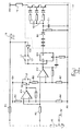
- this shows generally a circuit for controlling a fail-safe operation of measurement and control apparatus (not shown) such as is used in a steam raising plant to monitor the water level in a steam generation vessel.
- a sensor 10 comprises an electrode which in use is inserted into a water/steam column (not shown) to detect the presence or absence of water.
- Typical applications of such apparatus include low or high level alarms on steam drums, feed heaters, deareators and turbine water induction prevention systems on steam lines.
- the apparatus detects the presence or absence of water by making a measurement of the impedance experienced in a gap between an insulated tip of the electrode and a surface held at a reference voltage or else connected to ground.
- the impedance measured when water is present is considerably less than that measured when water is absent.
- the apparatus may be configured to provide an alarm when water is present and should not be, or vice versa.
- the circuit comprises comparators IC1 and IC2, a phase detector IC3 and a triple-redundant drive circuit 12 which drives a relay 14.
- IC1 The function of IC1 is to ensure that when operating with water as the normal condition, an electrode fault, such as could be caused by excessive contamination, will cause the system output to indicate an abnormal condition.
- IC2 The main function of IC2 is to discriminate between the water condition and the steam condition.
- IC3 The function of IC3 is to ensure that there is no output if there exists an abnormal condition or any fault condition. It follows that there will only be an output if the sensor is in the normal condition. This is then shown to operate a relay using a secure triple redundancy drive circuit so that the relay contacts may be used to indicate a normal or an abnormal/fault condition.
- the electrode 10 is driven by a low frequency square wave (clock) signal 16 via resistance R1.
- the electrode forms a potential divider with R1, the amplitude of the signal returned via R2 being dependent upon the resistance of the electrode 10,
- IC1 is a comparator which acts as an electrode fault detector and which receives at its inverting input, the signal from R2. This is compared to the voltage level at the non-inverting input as formed by the potential divider R3 and R4 such that, if the signal from R2 is less than that at the non-inverting input, the output from IC1 is at a high state.
- the output of IC1 is an alternating signal which when applied to the gate of a transistor TR1, switches current through resistors R6 and R7.
- the resultant signal at the non-inverting input to IC2 is in phase with the clock 16 and has a maximum level as defined by the ratio of R6 and R7.
- the inverting input of IC2 receives the electrode signal via R2 and this also is in phase with clock 16.
- the maximum signal level at the non-inverting input to IC2 is set so that, for a water condition, there will be an alternating signal at the output of IC2 which is in phase with the clock 16.
- the signal at the inverting input to IC2 will always be more positive than the signal on the non-inverting input since the impedance of the electrode 10 will be higher. In consequence there will be no alternating output from IC2.
- IC1 should fail in a manner which causes no current to flow through R6 and R7, it places the non-inverting input to IC2 at the negative rail voltage and thus prevents IC2 from outputting a signal. If IC1 should fail in a manner which causes current to flow through R6 and R7, it places the non-inverting input to IC2 at the water/steam threshold voltage. It follows that under water conditions, IC2 will give no output and under steam conditions, an alternating output which is out of phase with the clock 16. If IC2 should fail, its output will go to either a high or low d.c. state. All of the above mentioned output conditions cause IC3 to give no output which is indicative of an abnormal or fault condition.
- IC3 is a D Type flip flop circuit with positive edge trigger. It receives the output from IC2 on its D input and the inverted clock signal from inverter IC4 on its clock input. The output from IC2 is also used as the reset signal. Both the D input and the clock input are derived from clock 16, however the switching of the D input is slightly delayed with respect to the clock input due to its passage through the electrode circuit and IC1/IC2. In consequence, it is only when these signals are out of phase that the output of IC3 changes. It is then reset half a cycle later to give an alternating output from IC3. It follows that if the input signals are in phase or if there is no signal on either of these inputs, the output will not be alternating.
- the relay drive circuit 12 uses an a.c. detector to drive the relay.
- the a.c. signal from IC3 will, on its positive cycle, charge the capacitor C1 through D1 and will also switch the transistors 18 to energise the relay 14. During the negative cycle these transistors will remain on due to the stored energy in capacitor C1.
- the size of C1 is chosen such that, if the a.c. signal ceases, the relay will be de-energised within five clock cycles.
- the three charging capacitors in series with D1 and the three transistor drive circuits are used to provide triple redundancy to achieve a secure relay drive arrangement. Thus the system indicates a normal condition if water is present and there are no faults and an abnormal condition if steam is present and/or there is a fault.
- IC1 serves no function in the circuit and the non-inverting input to IC2 is set to a d.c. threshold level for the switching from steam to water. Only in the steam condition is the signal from R2, which is applied to the inverting input of IC2, of sufficient value to cause IC2 to output a signal which is antiphase with the clock 16. In all other conditions, which include open or short circuits in the electrode 10, contamination of the electrode or failure of IC2, cause IC2 to go either to a high or a low d.c. state.
- IC2 which in the normal steam conditions is a signal in antiphase with clock 16
- IC3 which in this configuration receives its clock signal direct from clock 16 via L1. Since these two signals are antiphase, IC3 outputs an a.c. signal which in turn drives the relay to indicate the normal condition. If the electrode is in water or there is any fault condition the relay outputs an abnormal condition.
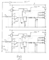
- FIG 2 an alternative arrangement is shown which does not embody the invention and in which the circuit is simplified by the removal of one comparator circuit (i.e. IC1 of the circuit of Figure 1 ) and then the resultant circuit is duplicated.
- the upper circuit 20 is used primarily to detect the water/steam status and the lower circuit 30 is used primarily to detect an electrode failure condition as results if the electrode is indicating a conductivity of less than 100 ⁇ S/cm.
- This difference being defined by selection of the resistive values of R8, R9, R10 and R11.
- Each circuit will indicate an abnormal condition if there is a component failure within its circuit, but only the upper circuit 20 will indicate an abnormal condition if the water or steam status changes into the abnormal condition.
- the clock 16 is common to both upper and lower circuits 20, 30.
- the contacts (not shown) of the relays 14a and 14b, of the upper and lower circuits 20 and 30 respectively, must be connected together.
Landscapes
- Physics & Mathematics (AREA)
- Fluid Mechanics (AREA)
- General Physics & Mathematics (AREA)
- Engineering & Computer Science (AREA)
- Signal Processing (AREA)
- Thermal Sciences (AREA)
- Safety Devices In Control Systems (AREA)
- Investigating Or Analyzing Materials By The Use Of Electric Means (AREA)
- Control Of Non-Electrical Variables (AREA)
- Measurement Of Levels Of Liquids Or Fluent Solid Materials (AREA)
Claims (11)
- Elektrische Sensorschaltung, wobei die Schaltung Folgendes beinhaltet:eine Einrichtung (16, R1), die angeordnet ist, um ein wechselndes elektrisches Signal an einen Sensor (10) anzulegen, das an dem Sensor (10) gemäß einem von dem Sensor (10) erfassten Zustand zu dämpfen ist,eine Ausgangsstufe (12), die so angeordnet ist, dass sie entweder eine normale Bedingung oder eine Fehlerbedingung anzeigt,einen Fehlerdetektor (R3, R4, IC1), der angeordnet ist, um das gedämpfte Signal zu empfangen und zu verursachen, dass die Ausgangsstufe (12) der Schaltung eine Fehlerbedingung anzeigt, wenn der Fehlerdetektor (R3, R4, IC1) an dem Sensor (10) einen offenen Stromkreis oder einen Kurzschluss erkennt, undeine erste Vergleichseinrichtung (IC2, R6, R7), die angeordnet ist, um das gedämpfte Signal zu empfangen und einen Wert des gedämpften Signals mit einem Referenzwert zu vergleichen und um zu verursachen, dass die Ausgangsstufe (12) eine Fehlerbedingung anzeigt, wenn der Wert des gedämpften Signals auf eine abnormale Bedingung an dem Sensor (10) schließen lässt, dadurch gekennzeichnet, dass
die erste Vergleichseinrichtung (IC2, R6, R7) so angeordnet ist, dass sie ein wechselndes Ausgangssignal mit einer vorbestimmten Phase relativ zu dem gedämpften Signal bereitstellt, wenn das gedämpfte Signal auf eine erfasste normale Bedingung schließen lässt, und gekennzeichnet durch
eine Auswähleinrichtung (L1, L2, L3), die so angeordnet ist, dass sie die Auswahl aus einer Vielzahl von Alternativen der Art der abnormalen Bedingung, die von der ersten Vergleichseinrichtung (IC2, R6, R7) ermittelt wurde, ermöglicht, und
eine zweite Vergleichseinrichtung (IC3, IC4), die angeordnet ist, um das Ausgangssignal von der ersten Vergleichseinrichtung (IC2, R6, R7) und das an den Sensor (10) angelegte wechselnde elektrische Signal zu empfangen, und die eine Phasendetektionseinrichtung aufweist, die zum Vergleichen der Phase des Ausgangssignals der ersten Vergleichseinrichtung (IC2, R6, R7) mit der Phase des an den Sensor (10) angelegten Signals angeordnet ist, und angeordnet ist, um die Ausgangsstufe (12) zum Anzeigen einer Fehlerbedingung zu veranlassen, wenn sich das Ergebnis des Phasenvergleichs von der vorbestimmten normalen Phasenbeziehung zwischen dem Ausgangssignal der ersten Vergleichseinrichtung und dem an den Sensor (10) angelegten wechselnden elektrischen Signal unterscheidet. - Schaltung nach Anspruch 1, dadurch gekennzeichnet, dass die Ausgangsstufe (12) zum Ansteuern einer Steuervorrichtung (14) angeordnet ist, die eine normale Bedingung und eine Fehlerbedingung hat, so dass die von der Steuervorrichtung (14) angenommene Bedingung der von der Ausgangsstufe (12) angezeigten Bedingung entspricht.
- Schaltung nach Anspruch 1 oder Anspruch 2, dadurch gekennzeichnet, dass die Ausgangsstufe (12) eine dreifach redundante Schalteinrichtung (18) zum Ansteuern der Steuervorrichtung (14) aufweist und die Schalteinrichtung drei Schalter hat, die jeweils allein in der Lage sind, die Steuervorrichtung (14) auf eine Fehlerbedingung umzuschalten.
- Schaltung nach einem der Ansprüche 1 bis 3, dadurch gekennzeichnet, dass das an den Sensor (10) angelegte wechselnde elektrische Signal eine beträchtlich niedrige Frequenz hat und eine im Wesentlichen rechteckige Schwingungsform hat.
- Schaltung nach Anspruch 4, dadurch gekennzeichnet, dass das wechselnde elektrische Signal ein Taktsignal aufweist.
- Schaltung nach einem der Ansprüche 1 bis 5, dadurch gekennzeichnet, dass die genannte, vom Sensor (10) erfasste Bedingung die Impedanz des Sensors (10) ist.
- Schaltung nach Anspruch 6, dadurch gekennzeichnet, dass die Auswähleinrichtung (L1, L2, L3) zum Wählen zwischen einer hohen erfassten Impedanz und einer niedrigen erfassten Impedanz als der abnormalen Bedingung angeordnet ist.
- Schaltung nach einem der Ansprüche 1 bis 7, dadurch gekennzeichnet, dass die erste Vergleichseinrichtung eine erste Vergleichsschaltung (IC2) aufweist.
- Schaltung nach einem der Ansprüche 1 bis 8, dadurch gekennzeichnet, dass der Fehlerdetektor (R3, R4, IC1) im Gebrauch zum Erkennen einer Fehlerbedingung mit hoher Leitfähigkeit oder einer Fehlerbedingung mit niedriger Leitfähigkeit am Sensor (10) angeordnet ist.
- Schaltung nach einem der Ansprüche 1 bis 9, dadurch gekennzeichnet, dass der Fehlerdetektor eine zweite Vergleichsschaltung (IC1) aufweist.
- Schaltung nach Anspruch 2, dadurch gekennzeichnet, dass die Steuervorrichtung wenigstens ein Relais (14) beinhaltet.
Applications Claiming Priority (2)
| Application Number | Priority Date | Filing Date | Title |
|---|---|---|---|
| GB9713678 | 1997-06-27 | ||
| GB9713678A GB2326779B (en) | 1997-06-27 | 1997-06-27 | Fail-safe system |
Publications (2)
| Publication Number | Publication Date |
|---|---|
| EP0887628A1 EP0887628A1 (de) | 1998-12-30 |
| EP0887628B1 true EP0887628B1 (de) | 2011-06-15 |
Family
ID=10815083
Family Applications (1)
| Application Number | Title | Priority Date | Filing Date |
|---|---|---|---|
| EP98304977A Expired - Lifetime EP0887628B1 (de) | 1997-06-27 | 1998-06-24 | Sicherheitseinrichtung |
Country Status (4)
| Country | Link |
|---|---|
| US (1) | US6118190A (de) |
| EP (1) | EP0887628B1 (de) |
| JP (1) | JPH11110002A (de) |
| GB (1) | GB2326779B (de) |
Families Citing this family (7)
| Publication number | Priority date | Publication date | Assignee | Title |
|---|---|---|---|---|
| US6650128B2 (en) | 2002-02-19 | 2003-11-18 | Tyco Flow Control | Method and apparatus for circuit fault detection with boiler water level detection system |
| US20050236498A1 (en) * | 2004-04-27 | 2005-10-27 | Cunningham Greg A | Systems and methods for dispensing liquids |
| FR2977027B1 (fr) * | 2011-06-24 | 2013-07-12 | Dev Electroniques Et Systemes Informatiques Desi | Procede et dispositif de detection d'un niveau de phase dans un recipient |
| US9767671B2 (en) * | 2014-11-05 | 2017-09-19 | Intel Corporation | System for determining sensor condition |
| CN109443486B (zh) * | 2018-10-25 | 2021-04-27 | 中国船舶重工集团公司第七一九研究所 | 一种阈值自适应电接点水位检测方法和检测装置 |
| CN110413456B (zh) * | 2019-07-30 | 2023-05-26 | 上海航天计算机技术研究所 | 三冗余数据逐级表决系统及方法 |
| CN118192518B (zh) * | 2024-04-15 | 2026-04-10 | 中国核电工程有限公司 | 核设施安全级控制系统的报警模块、方法及控制系统 |
Family Cites Families (16)
| Publication number | Priority date | Publication date | Assignee | Title |
|---|---|---|---|---|
| GB1056032A (en) * | 1964-04-08 | 1967-01-25 | Central Electr Generat Board | Improvements in or relating to fluid indicating apparatus |
| GB1438271A (en) * | 1972-05-10 | 1976-06-03 | Central Electr Generat Board | Alarm and/or control apparatus |
| GB1546587A (en) * | 1974-12-11 | 1979-05-23 | Commissariat Energie Atomique | Positive-safety units haveing the functions of control relay and current regulation |
| US4001654A (en) * | 1975-07-31 | 1977-01-04 | General Electric Company | Testable protective system |
| GB1605145A (en) * | 1978-05-11 | 1982-02-10 | Bullen P M | Alarm and/or control apparatus |
| GB1603934A (en) * | 1978-05-30 | 1981-12-02 | Central Electr Generat Board | Alarm and/or control apparatus |
| GB2083225B (en) * | 1980-08-11 | 1985-02-06 | Central Electr Generat Board | Fluid level sensor |
| US4467386A (en) * | 1982-11-17 | 1984-08-21 | Rca Corporation | Fail-safe sensor circuit |
| SE447603B (sv) * | 1985-04-02 | 1986-11-24 | Jonsson Bert | Sekerhetsarrangemang vid anordning for indikering av tryck eller kraft pa exv tryckknappar, kantskydd pa portar, trampmattor eller allmen positionsdetektering |
| US4631626A (en) * | 1985-09-27 | 1986-12-23 | Honeywell Inc. | Temperature controller with temperature limiting sensor |
| GB8907363D0 (en) * | 1989-03-31 | 1989-05-17 | Ass Elect Ind | Current monitors |
| GB2236388A (en) * | 1989-09-21 | 1991-04-03 | Bestquint Ltd | Signal sensing in fibre optic sensor control systems |
| GB9311187D0 (en) * | 1993-05-29 | 1993-07-14 | Schlumberger Ind Ltd | Fluid level sensing systems |
| US5438323A (en) * | 1993-06-14 | 1995-08-01 | Scully Signal Company | Fail safe fluid level detection circuit |
| GB2279749B (en) * | 1993-07-02 | 1996-12-04 | Motorola Inc | Short circuit detector for sensors |
| GB2290141B (en) * | 1994-06-09 | 1998-03-25 | Smiths Industries Plc | Fuel-gauging systems |
-
1997
- 1997-06-27 GB GB9713678A patent/GB2326779B/en not_active Expired - Fee Related
-
1998
- 1998-06-24 EP EP98304977A patent/EP0887628B1/de not_active Expired - Lifetime
- 1998-06-26 US US09/105,216 patent/US6118190A/en not_active Expired - Lifetime
- 1998-06-29 JP JP10219547A patent/JPH11110002A/ja active Pending
Also Published As
| Publication number | Publication date |
|---|---|
| GB2326779B (en) | 2001-06-06 |
| EP0887628A1 (de) | 1998-12-30 |
| GB9713678D0 (en) | 1997-09-03 |
| GB2326779A (en) | 1998-12-30 |
| JPH11110002A (ja) | 1999-04-23 |
| US6118190A (en) | 2000-09-12 |
Similar Documents
| Publication | Publication Date | Title |
|---|---|---|
| US4879624A (en) | Power controller | |
| US4926281A (en) | Fail-safe and fault-tolerant alternating current output circuit | |
| US5446451A (en) | On board hot bearing detector system with fault detection | |
| WO1994028354A1 (en) | Flame rectification sensor employing pulsed excitation | |
| EP0887628B1 (de) | Sicherheitseinrichtung | |
| US4811136A (en) | Phase controller for processing current and voltage faults | |
| US3992636A (en) | Digital input circuit with fault detection means | |
| US4687623A (en) | Self-compensating voted logic power interface with tester | |
| EP0723161B1 (de) | Fehlerüberwachungsanordnung für brückenschaltung | |
| EP0221775B1 (de) | Prüfbare Auswahllogik-Leistungsschaltung und Verfahren zu deren Prüfung | |
| US5579235A (en) | Method of monitoring rpm sensors | |
| JP2002501279A (ja) | 交流電源スイッチを監視する回路 | |
| JPH01144322A (ja) | 電気機器 | |
| JP3279811B2 (ja) | 制御機器用駆動装置 | |
| EP0460643B1 (de) | Sicherheitsschaltung für, zum Beispiel numerische Steuereinheit | |
| GB2183411A (en) | Testing fuses | |
| KR830002592B1 (ko) | 논리 회로 모니터 | |
| KR200225516Y1 (ko) | 디지털 직류접지 검출장치 | |
| JPH07280867A (ja) | バイパス接続装置 | |
| GB1605145A (en) | Alarm and/or control apparatus | |
| JPH077962A (ja) | インバータの故障検出装置 | |
| JPS6138363Y2 (de) | ||
| JPS6211915A (ja) | 電力系統の無効電力補償装置 | |
| JPH10341578A (ja) | インバータ装置のアーム短絡検出回路 | |
| JP3240479B2 (ja) | 微地絡区間標定装置 |
Legal Events
| Date | Code | Title | Description |
|---|---|---|---|
| PUAI | Public reference made under article 153(3) epc to a published international application that has entered the european phase |
Free format text: ORIGINAL CODE: 0009012 |
|
| AK | Designated contracting states |
Kind code of ref document: A1 Designated state(s): AT BE CH CY DE DK ES FI FR GB GR IE IT LI LU MC NL PT SE |
|
| AX | Request for extension of the european patent |
Free format text: AL;LT;LV;MK;RO;SI |
|
| 17P | Request for examination filed |
Effective date: 19990607 |
|
| AKX | Designation fees paid |
Free format text: DE FR GB IT |
|
| RAP1 | Party data changed (applicant data changed or rights of an application transferred) |
Owner name: SOLARTRON MOBREY LIMITED |
|
| 17Q | First examination report despatched |
Effective date: 20050628 |
|
| GRAP | Despatch of communication of intention to grant a patent |
Free format text: ORIGINAL CODE: EPIDOSNIGR1 |
|
| GRAS | Grant fee paid |
Free format text: ORIGINAL CODE: EPIDOSNIGR3 |
|
| GRAA | (expected) grant |
Free format text: ORIGINAL CODE: 0009210 |
|
| AK | Designated contracting states |
Kind code of ref document: B1 Designated state(s): DE FR GB IT |
|
| REG | Reference to a national code |
Ref country code: GB Ref legal event code: FG4D |
|
| REG | Reference to a national code |
Ref country code: DE Ref legal event code: R096 Ref document number: 69842308 Country of ref document: DE Effective date: 20110721 |
|
| PLBE | No opposition filed within time limit |
Free format text: ORIGINAL CODE: 0009261 |
|
| STAA | Information on the status of an ep patent application or granted ep patent |
Free format text: STATUS: NO OPPOSITION FILED WITHIN TIME LIMIT |
|
| 26N | No opposition filed |
Effective date: 20120316 |
|
| PG25 | Lapsed in a contracting state [announced via postgrant information from national office to epo] |
Ref country code: IT Free format text: LAPSE BECAUSE OF FAILURE TO SUBMIT A TRANSLATION OF THE DESCRIPTION OR TO PAY THE FEE WITHIN THE PRESCRIBED TIME-LIMIT Effective date: 20110615 |
|
| REG | Reference to a national code |
Ref country code: FR Ref legal event code: ST Effective date: 20120504 |
|
| REG | Reference to a national code |
Ref country code: DE Ref legal event code: R097 Ref document number: 69842308 Country of ref document: DE Effective date: 20120316 |
|
| PG25 | Lapsed in a contracting state [announced via postgrant information from national office to epo] |
Ref country code: FR Free format text: LAPSE BECAUSE OF NON-PAYMENT OF DUE FEES Effective date: 20110816 |
|
| PGFP | Annual fee paid to national office [announced via postgrant information from national office to epo] |
Ref country code: GB Payment date: 20170627 Year of fee payment: 20 |
|
| PGFP | Annual fee paid to national office [announced via postgrant information from national office to epo] |
Ref country code: DE Payment date: 20170628 Year of fee payment: 20 |
|
| REG | Reference to a national code |
Ref country code: DE Ref legal event code: R071 Ref document number: 69842308 Country of ref document: DE |
|
| REG | Reference to a national code |
Ref country code: GB Ref legal event code: PE20 Expiry date: 20180623 |
|
| PG25 | Lapsed in a contracting state [announced via postgrant information from national office to epo] |
Ref country code: GB Free format text: LAPSE BECAUSE OF EXPIRATION OF PROTECTION Effective date: 20180623 |