EP0887643B1 - Procédé de détermination de la teneur de composants dans des systèmes aqueux - Google Patents
Procédé de détermination de la teneur de composants dans des systèmes aqueux Download PDFInfo
- Publication number
- EP0887643B1 EP0887643B1 EP98250232A EP98250232A EP0887643B1 EP 0887643 B1 EP0887643 B1 EP 0887643B1 EP 98250232 A EP98250232 A EP 98250232A EP 98250232 A EP98250232 A EP 98250232A EP 0887643 B1 EP0887643 B1 EP 0887643B1
- Authority
- EP
- European Patent Office
- Prior art keywords
- combustion
- temperature
- detector
- sample
- vessel
- Prior art date
- Legal status (The legal status is an assumption and is not a legal conclusion. Google has not performed a legal analysis and makes no representation as to the accuracy of the status listed.)
- Expired - Lifetime
Links
Images

Classifications
-
- G—PHYSICS
- G01—MEASURING; TESTING
- G01N—INVESTIGATING OR ANALYSING MATERIALS BY DETERMINING THEIR CHEMICAL OR PHYSICAL PROPERTIES
- G01N33/00—Investigating or analysing materials by specific methods not covered by groups G01N1/00 - G01N31/00
- G01N33/18—Water
- G01N33/182—Specific anions in water
-
- G—PHYSICS
- G01—MEASURING; TESTING
- G01N—INVESTIGATING OR ANALYSING MATERIALS BY DETERMINING THEIR CHEMICAL OR PHYSICAL PROPERTIES
- G01N31/00—Investigating or analysing non-biological materials by the use of the chemical methods specified in the subgroup; Apparatus specially adapted for such methods
- G01N31/12—Investigating or analysing non-biological materials by the use of the chemical methods specified in the subgroup; Apparatus specially adapted for such methods using combustion
-
- G—PHYSICS
- G01—MEASURING; TESTING
- G01N—INVESTIGATING OR ANALYSING MATERIALS BY DETERMINING THEIR CHEMICAL OR PHYSICAL PROPERTIES
- G01N33/00—Investigating or analysing materials by specific methods not covered by groups G01N1/00 - G01N31/00
- G01N33/18—Water
- G01N33/1826—Organic contamination in water
- G01N33/1846—Total carbon analysis
-
- Y—GENERAL TAGGING OF NEW TECHNOLOGICAL DEVELOPMENTS; GENERAL TAGGING OF CROSS-SECTIONAL TECHNOLOGIES SPANNING OVER SEVERAL SECTIONS OF THE IPC; TECHNICAL SUBJECTS COVERED BY FORMER USPC CROSS-REFERENCE ART COLLECTIONS [XRACs] AND DIGESTS
- Y10—TECHNICAL SUBJECTS COVERED BY FORMER USPC
- Y10T—TECHNICAL SUBJECTS COVERED BY FORMER US CLASSIFICATION
- Y10T436/00—Chemistry: analytical and immunological testing
- Y10T436/17—Nitrogen containing
- Y10T436/176152—Total nitrogen determined
-
- Y—GENERAL TAGGING OF NEW TECHNOLOGICAL DEVELOPMENTS; GENERAL TAGGING OF CROSS-SECTIONAL TECHNOLOGIES SPANNING OVER SEVERAL SECTIONS OF THE IPC; TECHNICAL SUBJECTS COVERED BY FORMER USPC CROSS-REFERENCE ART COLLECTIONS [XRACs] AND DIGESTS
- Y10—TECHNICAL SUBJECTS COVERED BY FORMER USPC
- Y10T—TECHNICAL SUBJECTS COVERED BY FORMER US CLASSIFICATION
- Y10T436/00—Chemistry: analytical and immunological testing
- Y10T436/19—Halogen containing
- Y10T436/193333—In aqueous solution
-
- Y—GENERAL TAGGING OF NEW TECHNOLOGICAL DEVELOPMENTS; GENERAL TAGGING OF CROSS-SECTIONAL TECHNOLOGIES SPANNING OVER SEVERAL SECTIONS OF THE IPC; TECHNICAL SUBJECTS COVERED BY FORMER USPC CROSS-REFERENCE ART COLLECTIONS [XRACs] AND DIGESTS
- Y10—TECHNICAL SUBJECTS COVERED BY FORMER USPC
- Y10T—TECHNICAL SUBJECTS COVERED BY FORMER US CLASSIFICATION
- Y10T436/00—Chemistry: analytical and immunological testing
- Y10T436/20—Oxygen containing
- Y10T436/204998—Inorganic carbon compounds
-
- Y—GENERAL TAGGING OF NEW TECHNOLOGICAL DEVELOPMENTS; GENERAL TAGGING OF CROSS-SECTIONAL TECHNOLOGIES SPANNING OVER SEVERAL SECTIONS OF THE IPC; TECHNICAL SUBJECTS COVERED BY FORMER USPC CROSS-REFERENCE ART COLLECTIONS [XRACs] AND DIGESTS
- Y10—TECHNICAL SUBJECTS COVERED BY FORMER USPC
- Y10T—TECHNICAL SUBJECTS COVERED BY FORMER US CLASSIFICATION
- Y10T436/00—Chemistry: analytical and immunological testing
- Y10T436/23—Carbon containing
- Y10T436/235—In an aqueous solution [e.g., TOC, etc.]
-
- Y—GENERAL TAGGING OF NEW TECHNOLOGICAL DEVELOPMENTS; GENERAL TAGGING OF CROSS-SECTIONAL TECHNOLOGIES SPANNING OVER SEVERAL SECTIONS OF THE IPC; TECHNICAL SUBJECTS COVERED BY FORMER USPC CROSS-REFERENCE ART COLLECTIONS [XRACs] AND DIGESTS
- Y10—TECHNICAL SUBJECTS COVERED BY FORMER USPC
- Y10T—TECHNICAL SUBJECTS COVERED BY FORMER US CLASSIFICATION
- Y10T436/00—Chemistry: analytical and immunological testing
- Y10T436/25—Chemistry: analytical and immunological testing including sample preparation
- Y10T436/25125—Digestion or removing interfering materials
Definitions
- the invention relates to a method for determining Water ingredients according to the preamble of claim 1 and an apparatus for performing the method.
- Infrared detectors have been used as detectors for the carbon content, special chemiluminescence detectors for the nitrogen oxide content and so-called coulometric Proven detectors for the halide content.
- TOC total organic carbon
- a small amount of water with the transport gas is usually fed to an oven heated to a predetermined temperature with a resistance heater, where it evaporates and burns almost suddenly, and the combustion gas is fed to an NDIR-CO 2 detector, the CO 2 content indicator of which is a measure of forms the C content of the water sample.
- An advanced version of this method and a corresponding apparatus are described in DE 43 44 441 C2.
- An arrangement modified to measure very low TOC values - for example in high-purity water or high-purity solutions for medical applications - is described in EP 0 684 471 A2.
- a method remedies the latter problem, in which an aqueous sample is heated and burned relatively slowly in an initially cold heating vessel in discontinuous analysis processes; see. DE 44 12 778 C1.
- the CO 2 content of the combustion gas must be tracked and integrated over a certain period of time in this discontinuous process.
- This method avoids strong pressure fluctuations in the equipment and therefore larger amounts of sample can be used.
- the necessary tracking of the time dependence of the CO 2 concentration down to the range of very low values requires a highly sensitive and correspondingly expensive detector, which still works precisely in this range, as well as a precision integrator.
- the expenditure on equipment increases further by providing a second heating device.
- the invention is therefore based on the object of being inexpensive and method suitable for routine operation with high measuring accuracy for specific determination of water constituents, in particular the TOC, and a Specify device for performing the method.
- the task is carried out with regard to the procedural aspect a method with the features of claim 1 and with regard the device aspect by a device solved with the features of claim 15.
- the invention includes the idea of replacing the known quasi-stationary process, which is based on the evaporation and combustion of very small amounts of water in a furnace which is kept permanently at the combustion temperature, by a dynamic two-step process with individual evaporation and combustion processes. Thanks to a special procedure, the detection of very low CO 2 concentrations is not necessary and therefore the use of a highly sensitive, expensive detector is not necessary.
- the evaporation temperature in the range between 100 ° C and 300 ° C, preferably between 100 ° C and 150 ° C, and the combustion temperature above 700 ° C, preferably between 800 ° C and 1000 ° C.
- Warming up to the vaporization temperature in the first Step can take approximately between 10 s and 200 s and heating to the combustion temperature in the second step in a time period between 5 s and 120 s be made. Long periods of time enable implementation relatively large sample volumes in the measuring apparatus gentle and are preferable, if not special short cycle time required for the measurements is.
- the temperature advantageously for a predetermined period of time, preferably between 10s and 60s, kept essentially constant.
- the combustion product obtained in the second step is fed to a CO 2 detector, in particular an NDIR detector, for determining the carbon content.
- a CO 2 detector in particular an NDIR detector
- the steps of evaporation and combustion are preceded by a step of separating inorganic carbon compounds from the sample, in particular by acidic degassing, since these would falsify the measured CO 2 value by pretending that the TOC was too high.
- the content of inorganic carbon can advantageously be determined immediately, in particular by supplying the degassing product to the CO 2 detector before the step of combustion.
- this quantification is dispensable, these carbon compounds can also be easily eliminated by a CO 2 scavenger.
- Nitrogen compounds so that is obtained in the second step Combustion product a nitrogen detector, in particular a chemiluminescence detector, for determination the nitrogen oxide content in the combustion gas / carrier gas mixture fed.
- the evaporation step a step of separating halide, in particular Chloride ions downstream.
- the separation can, if necessary, also be a salary determination the halide ions - in particular by means of a electrolytic (coulometric) process immediately on Separation reagent - to be performed.
- the gas obtained in the evaporation step which essentially consists of water vapor, is condensed in a cold trap to form an aqueous solution, and the step of separating halide ions is carried out in the cold trap by means of a suitable agent, in particular AgNO 3 solution or silver wadding ,
- a device for performing the method outlined above has a low inertia cyclically as a heating device furnace to be operated with low thermal mass, in particular an optical (infrared) radiation oven, on that with a responsive temperature-time control is provided.
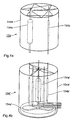
- a suitable radiation oven has a plurality of a cylindrical outer surface arranged around the reaction vessel Halogen heating rods and one the halogen heating rods surrounding cylindrical reflector.
- the radiation furnace comprises an elliptical one Reflector, in one focal line the reaction vessel and a halogen heating element is arranged in the other focal line is.
- the measuring apparatus as a whole is preferably designed as a branched system which can be closed off from the atmosphere and which has at least one reaction or Combustion vessel comprising ring line connecting the detector.
- the apparatus further comprises a degassing device on the output side connected to the detector for acidic degassing of the sample and a CO 2 trap which can be ground into a line between the degassing device and the detector.
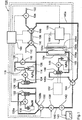
- FIG. 1 shows a TOC measuring arrangement 100 for determining the total organic carbon content of one (in the figure (not shown) aqueous sample.
- the arrangement includes a sample suction port 102 for sampling via a suction pump 104.
- the sample intake port 102 opens downstream the pump 104 into a two-way valve 106, which in turn in a line section 108 with exactly defined Dimensions (cross section and length) and empties that downstream is limited by another two-way valve 110. Sucking in sample solution using the suction pump 104 into the line section 108 towards the intake manifold 102 open valve 106 and closed valve 110 promotes a predetermined by the dimensions of the line section 108 Sample volume of, for example, 2-5 ml in the Device 100.
- a drain port 112 and a connecting line 114 extend from the valve 110, into which a gas line 120 connected to an oxygen tank 118 opens via a shut-off valve 116 and which in turn opens into a first gas washing bottle 122.
- the wash bottle 120 with a capacity of approximately 10 ml is used for acidic degassing of the sample by means of an H 3 PO 4 solution which is introduced therein and is fed from a storage vessel 126 via a metering pump 124; see also below.
- a further connecting line 128 branches off from the wash bottle 122 and branches into two line branches 128 a and 128 b, which lead to two connections of a further two-way valve 130.
- a further gas washing bottle 132 with a useful volume of approximately 10 ml is arranged in branch 128a, into which NaOH solution can be metered via a metering pump 134 from a storage container 136 and which - in a manner shown in more detail below - serves as a CO 2 trap.
- NaOH solution consumed during a measurement must then be discarded, which can be done by suction in a collecting vessel; the components required for this are not shown in the figure for the sake of clarity.
- the output of the two-way valve 130 is connected via a feed pump 138 and a further connecting line 140, into which an NDIR-CO 2 detector 142 is looped, to a further two-way valve 144, which opens into two branch lines 140a and 140b. While line 140a leads directly to the second inlet of the above-mentioned two-way valve 106, a further wash bottle 146 is first provided in line 140b opening into line 114 near valve 144, which is connected via a metering pump 148 with a storage container 150 for AgNO 3 solution connected is.
- the chloride catcher is optionally assigned a coulombmetric TOX measuring device 152, known per se, for detecting the halide content — shown here only as a block shown in dashed lines.
- a radiation oven 154 for evaporation and combustion of the sample.
- This includes one reaction vessel 154a and one via a heater control 156 connected to a heating current source 158 Heater rod 154b and a temperature sensor 154c in one internally reflective housing 154d; see. also Fig. 4a. His The outlet opens into the connection line 114 mentioned above.
- the entire device is controlled by a microprocessor program controller (Controller) 160 controlled.
- the sequence The measuring procedure is basically as follows:
- the sample suction valve 106 and the O 2 valve 116 are closed and the line section 108 containing the sample is looped into the arrangement by opening the valve 110 to line 114, the valve 130 going to line branch 128b and the valve 144 going to line branch 140a is open and the line branches 128a and 140b thus remain blocked.
- the feed pump 138 By switching on the feed pump 138, the sample is conveyed into the wash bottle 122 for acid degassing.
- the inorganic carbon compounds dissolved CO 2 , H 2 CO 3 , hydrogen carbonates and carbonates contained in the sample, which give the TIC, are converted into CO 2 dissolved in the sample water.
- the mixing with the oxygen in the line system causes the so-called stripping, ie the CO 2 is taken over into the gas phase and can be detected in this by the infrared detector 142.
- the TIC content of the sample can first be determined. If the volume of the gas circuit is exactly known, the TIC can be quantified as an absolute measurement.
- valve 130 by switching valve 130 to line branch 128a, CO 2 trap 132 is switched into the circuit and at the same time "bypass" 128b is shut off, thereby removing the CO 2 from the cycle gas. If the separate detection of the TIC is dispensable, this valve position can be used from the start, which saves analysis time.
- the CO 2 scavenger is switched off by switching the Valve 130 is switched off again and, by switching valve 144 instead of line branch 140a, branch 140b with furnace 154 and chloride trap 146 is switched into the circuit.
- the TIC-free sample including the phosphoric acid introduced, is pressed into the furnace 154.
- a stable setting of the basic CO 2 value at the CO 2 detector 142 is then awaited. (This can be done both by operating personnel or by means of an automatic measured value comparison via controller 160. In the latter case, of course, there must be a data connection from detector 142 to controller 160.)
- the oven 154 is first heated to a first temperature for relatively slow evaporation of the water (for example 120 ° C.) under program control by the controller 160 and the heating controller 156.
- the water vapor is condensed in the condenser / chloride trap 146 and at the same time freed of Cl - ions to protect the arrangement against corrosion by AgCl precipitation. J - and Br - ions can also be bound in the same way.
- the furnace is heated up to 800-900 ° C. in a second in a second heating phase and the part of the sample remaining after the water has evaporated is thereby burned within approx. 30 s.
- the Cl - and possibly other halide ions are bound in the chloride scavenger 146.
- the total organic carbon fractions of the sample (TOC including the volatile fractions - VOC) are converted into CO 2 and detected integrally in the NDIR detector 142. Since the gas circulation and the sample volume are known, an absolute measurement with high accuracy is possible. The integrating measurement in a closed sample / gas circuit avoids the need in the prior art for the exact detection of very small CO 2 concentrations in the decay area of the combustion and thus the use of an expensive, highly sensitive detector.
- the radiation oven 154 is due to its low thermal Mass cooled quickly and for a new measuring process ready, which enables short measuring cycle times. He can additionally have a fan for even faster cooling, as shown in Fig. 4b. Basically in the Arrangement 100, however, is another furnace with less thermal inertia can be used.
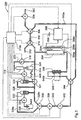
- the structure of the measuring arrangement 200 according to FIG. 2 is initially simplified in this way. that the CO 2 trap with accessories and the corresponding line branch and the associated two-way valve are dispensed with.
- the TIC as a basic signal is necessarily included in the CO 2 measured values.
- the TOC can be determined subtractively in this arrangement, for which purpose the detector also has a measured value memory 142a and a subtraction stage 142b which are assigned via the Controller 160 can be controlled.
- the wash bottle 146 acts exclusively as a cold trap and is filled with (high-purity) water instead of AgNO 3 in an operating cost-saving manner. Accordingly, no device for determining the halide content (TOX) is naturally provided.
- the wash bottle 146 acting as a condenser / chloride scavenger according to FIG. 1 is replaced by a heat sink 346 with a Peltier cooler 345, and the CO2 measured values are used by the IR spectrometer 342 for processing and outputting a control and processing unit Hand over 360.
- the cooled pipe section can be filled with cotton wool.
- An additional solenoid valve 321 between the line sections 314 and 328b enables a temporary bypassing of the acidic degassing as a whole in the arrangement 300, which makes it possible to record the volatile carbon fractions (VOC) separately from the TOC in an additional measuring step.
- the invention is not limited in its execution the preferred embodiments given above. Rather, a number of variants are conceivable, which of the solution shown, even with different types Make use.
- the heating of the sample can also be gradually added to two separate vessels or "Ovens" are made, the first of which is low inertia controllable heating device in the sense of the above description has, while the second - the actual combustion serving - preferably essentially at constant temperature is held.
- the temperature of the first vessel will then between an evaporating temperature and one clearly above this temperature (preferably above of approx. 400 ° C) changed.
- a suitable catalyst bound to a support e.g. Be
- An NDIR spectrometer does not necessarily have to be used as a CO 2 detector; alternatively, for example, the CO 2 can be converted into carbonic acid and a pH sensor can be used.
Landscapes
- Health & Medical Sciences (AREA)
- Life Sciences & Earth Sciences (AREA)
- Chemical & Material Sciences (AREA)
- Pathology (AREA)
- General Physics & Mathematics (AREA)
- Engineering & Computer Science (AREA)
- Physics & Mathematics (AREA)
- Analytical Chemistry (AREA)
- Biochemistry (AREA)
- General Health & Medical Sciences (AREA)
- Immunology (AREA)
- Food Science & Technology (AREA)
- Medicinal Chemistry (AREA)
- Combustion & Propulsion (AREA)
- Molecular Biology (AREA)
- Investigating Or Analyzing Non-Biological Materials By The Use Of Chemical Means (AREA)
- Investigating Or Analysing Materials By The Use Of Chemical Reactions (AREA)
Claims (20)
- Procédé pour la détermination d'une substance contenue dans de l'eau, en particulier du contenu en carbone et/ou azote organique/s, dans lequel un échantillon aqueux est évaporé et brûlé dans un récipient de chauffage (154a ; 154a' ; 254 ; 354) muni d'au moins un moyen de chauffage (154 ; 154' ; 254 ; 354), et le produit de la combustion est amené dans un flux de gaz de transport à un détecteur (142 ; 242 ; 342) pour la détermination de la concentration d'un composé gazeux de la substance contenue, l'un ou un premier récipient de chauffage présentant au moment de l'alimentation de l'échantillon aqueux une température au-dessous de ou au maximum dans le rayon de la température d'ébullition de l'échantillon et qui est augmentée après alimentation de l'échantillon, caractérisé en ce que l'échantillon est chauffé par le même moyen de chauffage dans une première étape partant d'une température initiale au-dessous de la température d'ébullition à une température d'évaporation, et est chauffé dans une deuxième étape à une température considérablement plus élevée, et que le produit de combustion est retenu dans un circuit qui est fermé pendant l'analyse.
- Procédé selon la revendication 1, caractérisé en ce qu'exactement un récipient de chauffage configuré comme récipient de combustion est utilisé, et que la température est augmentée à une température de combustion dans la deuxième étape.
- Procédé selon la revendication 1, caractérisé en ce que la première et la deuxième étape sont réalisées dans un premier récipient de chauffage, et une étape additionnelle de combustion est réalisée dans un deuxième récipient de chauffage configuré comme récipient de combustion et qui est essentiellement maintenu à une température de combustion constante.
- Procédé selon la revendication 2 ou 3, caractérisé en ce que la température d'évaporation est comprise dans le rayon entre 100°C et 300°C, de préférence entre 100°C et 150°C, et que la température de combustion est au-dessus de 700°C, de préférence entre 800°C et 1000°C.
- Procédé selon les revendications 1 ou 2, caractérisé en ce que l'échauffement à la température d'évaporation dans la première étape est effectué dans une période de temps comprise entre 10 s et 200 s, et que l'échauffement à la température de combustion dans la deuxième étape est effectué dans une période de temps comprise entre 5 s et 120 s.
- Procédé selon l'une quelconque des revendications précédentes, caractérisé en ce qu'à la suite de la première étape, la température est maintenue essentiellement constante pendant une période de temps prédéterminée, de préférence comprise entre 10 s et 60 s.
- Procédé selon l'une quelconque des revendications précédentes, caractérisé en ce que le produit de combustion obtenu dans la deuxième étape est amené à un détecteur de CO2, en particulier un détecteur IRND (142 ; 242 ; 242), pour la détermination du contenu en carbone.
- Procédé selon la revendication 7, caractérisé en ce que les étapes d'évaporation et de combustion sont précédées d'une étape de séparation des composés inorganiques du carbone de l'échantillon, en particulier par dégazage acide.
- Procédé selon la revendication 8, caractérisé en ce qu'en combinaison avec l'étape de séparation des composés inorganiques du carbone, une détermination du contenu en carbone inorganique est effectuée, en particulier par l'alimentation du détecteur de CO2 avec le produit de dégazage avant l'étape de combustion.
- Procédé selon l'une quelconque des revendications précédentes, caractérisé en ce que le produit de combustion est amené à un détecteur d'azote, en particulier un détecteur de chimioluminescense pour la détermination du contenu en azote.
- Procédé selon l'une quelconque des revendications précédentes, caractérisé en ce que l'étape d'évaporation est suivie d'une étape de séparation des ions de haloïde, en particulier des ions de chlorure.
- Procédé selon la revendication 11, caractérisé en ce qu'en combinaison avec l'étape de séparation, une détermination du contenu en ions de haloïde est effectuée, en particulier par un procédé coulométrique.
- Procédé selon l'une quelconque des revendications précédentes, caractérisé en ce que le gaz obtenu dans l'étape d'évaporation consistant essentiellement en vapeur d'eau, est condensé dans un piège cryogénique.
- Procédé selon la revendication 13 et les revendication 11 ou 12, caractérisé en ce que l'étape de séparation des ions de haloïde est effectuée dans le piège cryogénique dans un agent appropriée, en particulier Ag ou AgNO3.
- Dispositif pour réaliser le procédé selon l'une quelconque des revendications précédentes, caractérisé en ce que le moyen de chauffage du ou du premier récipient de chauffage est formé par un radiateur optique (154 ; 154' ; 254 ; 254) équipé d'une commande de température et de temps (146 ; 256 ; 356) à réponse rapide.
- Dispositif selon la revendication 15, caractérisé en ce que le radiateur (154') comporte une pluralité de bâtons de chauffage halogène (154b') disposés autour du récipient de combustion (154a') sur une enveloppe du cylindre, et un réflecteur elliptique (154d') entourant les bâtons de chauffage halogène.
- Dispositif selon la revendication 15, caractérisé en ce que le radiateur comporte un réflecteur cylindrique ayant une section transversale elliptique (154d), dans l'une de ses lignes focales un récipient de combustion (154a) est disposé, et dans l'autre de ses lignes focales un bâton de chauffage halogène (154b).
- Dispositif selon l'une quelconque des revendications 15 à 17, caractérisé par la configuration en tant que système branché (100 ; 200 ; 300) qui peut être isolé de l'atmosphère et dans lequel est prévue au moins une conduite circulaire (140b, 140, 128b, 114 ; 240b, 240, 228b, 214 ; 340b, 340, 328b, 314) reliant le récipient de combustion (154a ; 254a ; 354a) au détecteur (142 ; 242 ; 342).
- Dispositif selon la revendication 18, caractérisé par un moyen de dégazage (122 ; 222 ; 322) relié côté sortie au détecteur (142 ; 242 ; 342) pour le dégazage acide de l'échantillon.
- Dispositif selon la revendication 19, caractérisé par un dispositif de captage du CO2 (132 ; 332) qui peut être bouclé dans un conduit entre le moyen de dégazage et le détecteur.
Applications Claiming Priority (2)
| Application Number | Priority Date | Filing Date | Title |
|---|---|---|---|
| DE19727839A DE19727839A1 (de) | 1997-06-24 | 1997-06-24 | Verfahren zur Bestimmung eines Wasserinhaltsstoffes |
| DE19727839 | 1997-06-24 |
Publications (2)
| Publication Number | Publication Date |
|---|---|
| EP0887643A1 EP0887643A1 (fr) | 1998-12-30 |
| EP0887643B1 true EP0887643B1 (fr) | 2002-05-22 |
Family
ID=7834148
Family Applications (1)
| Application Number | Title | Priority Date | Filing Date |
|---|---|---|---|
| EP98250232A Expired - Lifetime EP0887643B1 (fr) | 1997-06-24 | 1998-06-24 | Procédé de détermination de la teneur de composants dans des systèmes aqueux |
Country Status (4)
| Country | Link |
|---|---|
| US (1) | US6143568A (fr) |
| EP (1) | EP0887643B1 (fr) |
| DE (2) | DE19727839A1 (fr) |
| ES (1) | ES2178104T3 (fr) |
Cited By (2)
| Publication number | Priority date | Publication date | Assignee | Title |
|---|---|---|---|---|
| DE102007004339A1 (de) | 2007-01-29 | 2008-08-07 | Lar Process Analysers Ag | Verfahren und Vorrichtung zur Bestimmung des Phosphorgehaltes einer wässrigen Probe |
| DE102018105611A1 (de) | 2018-03-12 | 2019-09-12 | Lar Process Analysers Ag | Messanordnung und Messverfahren zur Bestimmung eines Inhaltsstoffes oder Qualitätsparameters von Wasser oder Abwasser |
Families Citing this family (13)
| Publication number | Priority date | Publication date | Assignee | Title |
|---|---|---|---|---|
| DE19820800C2 (de) * | 1998-05-09 | 2001-06-28 | Henkel Kgaa | Automatische Bestimmung der Belastung von wäßrigen Reinigungslösungen mit kohlenstoffhaltigen Verbindungen |
| DE19902277A1 (de) * | 1999-01-21 | 2000-07-27 | Lar Analytik & Umweltmestechni | Verbrennungsofen für die Verbrennung von flüssigen Proben |
| IT1310403B1 (it) * | 1999-06-24 | 2002-02-13 | Univ Bologna | Dispositivo per l'analisi di composti organici, particolarmente incampioni acquosi e gassosi. |
| DE19931801C2 (de) * | 1999-07-08 | 2002-08-08 | Idc Geraeteentwicklungsgmbh | Verfahren zur Peakintegration für NDIR-detektierte Gasanalysen nach elementanalytischen Aufschlüssen |
| DE10012730C1 (de) * | 2000-03-16 | 2001-07-05 | Rainer Fiebig | Verfahren zur quantitativen Bestimmung oxidierbarer Wasserinhaltsstoffe und Vorrichtung zur Durchführung des Verfahrens |
| DE10240410B3 (de) * | 2002-09-02 | 2004-02-05 | Lar Analytik Und Umweltmesstechnik Gmbh | Verfahren zur Bestimmung des Sauerstoffbedarfs einer wässrigen Lösung für einen Klärprozess |
| DE20317754U1 (de) * | 2003-11-17 | 2004-09-16 | Analysenmesstechnik Bernath Atomic Gmbh & Co. Kg | Vorrichtung zum Abtrennen flüchtiger organischer Kohlenstoffverbindungen von einer Prozessflüssigkeit |
| DE102006058051B4 (de) * | 2006-12-07 | 2014-07-10 | Endress + Hauser Conducta Gesellschaft für Mess- und Regeltechnik mbH + Co. KG | Verfahren zur Überwachung der Konzentration eines Wasserinhaltsstoffes in einem wässrigen Medium |
| CN101796393B (zh) * | 2007-09-05 | 2013-06-19 | 通用电气分析仪器公司 | 用于处理包含有机材料的含水试样的装置及其利用方法 |
| CN117517404A (zh) | 2014-05-23 | 2024-02-06 | Bl 科技公司 | 用于检测气阱失效的熔丝 |
| DE102015118586A1 (de) | 2015-10-30 | 2017-05-04 | Lar Process Analysers Ag | Probenverdünnung |
| CN108225405B (zh) * | 2017-12-29 | 2021-05-14 | 中山赛特奥日用科技有限公司 | 一种家用剂液加热器加热剂液的挥发效果的分析方法 |
| CN115427805A (zh) * | 2019-12-11 | 2022-12-02 | Bl科技公司 | 通过电阻加热产生的高温高压的氧化测定含水样品中的碳 |
Family Cites Families (12)
| Publication number | Priority date | Publication date | Assignee | Title |
|---|---|---|---|---|
| US3840341A (en) * | 1972-03-03 | 1974-10-08 | Ionics | Organic carbon method and analyzer |
| US3892528A (en) * | 1973-04-02 | 1975-07-01 | Oceanography Int Corp | Method and apparatus for vaporizing liquids to be contacted with a carrier gas |
| GB2029014A (en) * | 1978-08-28 | 1980-03-12 | Envirotech Corp | A method of determining total organic halides in water |
| US4227887A (en) * | 1978-08-28 | 1980-10-14 | Envirotech Corporation | Determination of total organic halides in water |
| US4977094A (en) * | 1987-12-28 | 1990-12-11 | Ionics, Incorporated | Process for monitoring the quality of water |
| US5116736A (en) * | 1988-02-19 | 1992-05-26 | Shimadzu Corporation | Method for the quantitative determination of micro-organisms or pyrogens |
| DE4115425C1 (fr) * | 1991-05-10 | 1992-08-27 | Hartmann & Braun Ag, 6000 Frankfurt, De | |
| JP2541418B2 (ja) * | 1992-03-26 | 1996-10-09 | 株式会社島津製作所 | Poc測定装置 |
| DE4231727C2 (de) * | 1992-09-23 | 1997-07-31 | Idc Geraeteentwicklungsgesells | Verfahren und Vorrichtung zur Verbrennung von analytischen Feststoffproben in einer Vertikalverbrennungsapparatur |
| US5509733A (en) * | 1993-12-21 | 1996-04-23 | Ta Instruments, Inc. | Infrared heated differential thermal analyzer |
| DE4344441C1 (de) * | 1993-12-24 | 1995-07-13 | Siepmann Friedrich W | Verfahren und Vorrichtung zur kontinuierlichen Bestimmung des Gehalts an oxidierbaren Inhaltsstoffen in wäßrigen Flüssigkeiten |
| JP3265830B2 (ja) * | 1994-05-27 | 2002-03-18 | 株式会社島津製作所 | 全有機体炭素計 |
-
1997
- 1997-06-24 DE DE19727839A patent/DE19727839A1/de not_active Withdrawn
-
1998
- 1998-06-24 US US09/103,585 patent/US6143568A/en not_active Expired - Fee Related
- 1998-06-24 DE DE59804171T patent/DE59804171D1/de not_active Expired - Lifetime
- 1998-06-24 EP EP98250232A patent/EP0887643B1/fr not_active Expired - Lifetime
- 1998-06-24 ES ES98250232T patent/ES2178104T3/es not_active Expired - Lifetime
Cited By (2)
| Publication number | Priority date | Publication date | Assignee | Title |
|---|---|---|---|---|
| DE102007004339A1 (de) | 2007-01-29 | 2008-08-07 | Lar Process Analysers Ag | Verfahren und Vorrichtung zur Bestimmung des Phosphorgehaltes einer wässrigen Probe |
| DE102018105611A1 (de) | 2018-03-12 | 2019-09-12 | Lar Process Analysers Ag | Messanordnung und Messverfahren zur Bestimmung eines Inhaltsstoffes oder Qualitätsparameters von Wasser oder Abwasser |
Also Published As
| Publication number | Publication date |
|---|---|
| DE59804171D1 (de) | 2002-06-27 |
| DE19727839A1 (de) | 1999-01-28 |
| EP0887643A1 (fr) | 1998-12-30 |
| ES2178104T3 (es) | 2002-12-16 |
| US6143568A (en) | 2000-11-07 |
Similar Documents
| Publication | Publication Date | Title |
|---|---|---|
| DE19727839A1 (de) | Verfahren zur Bestimmung eines Wasserinhaltsstoffes | |
| DE69636921T2 (de) | Verfahren zur spektroskopischen messung des konzentrationsverhältnisses zweier isotope in einem gas | |
| DE69516202T2 (de) | Instrument zur Messung organischer Nichtmethangase in Gasproben | |
| DE69520559T2 (de) | Verfahren und Vorrichtung für die Identifikation eines Anästhetikums in einem anästhetischen System | |
| DE1598927C3 (de) | Verfahren und Vorrichtung zur Analyse von Gasgemischen | |
| DE602004011795T2 (de) | Verfahren zur einführung von standardgas in ein probengefäss | |
| DE4437120C2 (de) | Verfahren und Vorrichtung zur on-line gekoppelten Deuteriumbestimmung | |
| EP1697739B1 (fr) | Procede et systeme pour determiner des substances contenues dans l'eau | |
| EP0637376B1 (fr) | Procede et dispositif pour mesurer la concentration d'un gaz indicateur dans un gaz de mesure contenant un gaz pertubateur | |
| DE19533510A1 (de) | Vorrichtung und Verfahren zur Bestimmung flüchtiger und/oder gelöster Komponenten in Flüssigkeiten oder Gasen | |
| DE2143415B2 (de) | Probenverdampfer-Apparatur | |
| EP1044357B1 (fr) | Procede et dispositif de mise en evidence quasi-continue de la presence de constituants inorganiques ou organiques dans des fluides | |
| DE19858366B4 (de) | Verfahren zum Herstellen und Abfüllen von quantitativ definierbaren Gasgemischen mit Komponenten in sehr geringer Konzentration | |
| DE19506875C1 (de) | Verfahren und Vorrichtung zur schnellen Bestimmung der Quecksilberkonzentration in Feststoffen | |
| DE3414866A1 (de) | Verfahren und vorrichtung zum messen der osmolaritaet von fluessigkeitsproben | |
| DE4231727C2 (de) | Verfahren und Vorrichtung zur Verbrennung von analytischen Feststoffproben in einer Vertikalverbrennungsapparatur | |
| DE69912032T2 (de) | Verfahren und Vorrichtung zur Entnahme von Aldehyden und Ketonen in Abgasen | |
| DE19836372A1 (de) | Heizeinheit zur Verdampfung einer Probe durch Erhitzung | |
| DE4234693A1 (de) | Probenkonzentrator- / loesungsmittelaustauschsystem | |
| DE2428608C3 (de) | Verfahren und Vorrichtung zur quantitativen Bestimmung von Gasen bzw. von zu Gasen reagierenden Stoffen in Substanzen, insbesondere in metallischen Proben | |
| DE3928102C2 (de) | Vorrichtung zur Überführung einer flüchtigen Meßprobe mittels eines Trägergases in die Meßanordnung eines Atomspektrometers | |
| DE4344324C1 (de) | Verfahren zur mengenmäßigen Ermittlung eines Gemischanteils in einem Gasgemisch | |
| DE10132390B4 (de) | Vorrichtung und Verfahren zur Analyse organischer Substanzen von Rein- oder Reinstwasser | |
| DE4309045A1 (de) | Verfahren und Vorrichtung zur elementselektriven Bestimmung des Summenparameters AOX in der Wasseranalytik mittels Kopplung der herkömmlichen AOX-Verbrennungsanalytik mit der Plasmaemissionsspektroskopie | |
| DE202017104833U1 (de) | Laborgerät zum Destillieren eines Gemisches |
Legal Events
| Date | Code | Title | Description |
|---|---|---|---|
| PUAI | Public reference made under article 153(3) epc to a published international application that has entered the european phase |
Free format text: ORIGINAL CODE: 0009012 |
|
| AK | Designated contracting states |
Kind code of ref document: A1 Designated state(s): DE ES FR GB IT NL |
|
| AX | Request for extension of the european patent |
Free format text: AL;LT;LV;MK;RO;SI |
|
| 17P | Request for examination filed |
Effective date: 19990629 |
|
| AKX | Designation fees paid | ||
| RBV | Designated contracting states (corrected) |
Designated state(s): DE ES FR GB IT NL |
|
| GRAG | Despatch of communication of intention to grant |
Free format text: ORIGINAL CODE: EPIDOS AGRA |
|
| GRAG | Despatch of communication of intention to grant |
Free format text: ORIGINAL CODE: EPIDOS AGRA |
|
| GRAH | Despatch of communication of intention to grant a patent |
Free format text: ORIGINAL CODE: EPIDOS IGRA |
|
| 17Q | First examination report despatched |
Effective date: 20011116 |
|
| GRAH | Despatch of communication of intention to grant a patent |
Free format text: ORIGINAL CODE: EPIDOS IGRA |
|
| GRAA | (expected) grant |
Free format text: ORIGINAL CODE: 0009210 |
|
| REG | Reference to a national code |
Ref country code: GB Ref legal event code: FG4D Free format text: NOT ENGLISH |
|
| REF | Corresponds to: |
Ref document number: 59804171 Country of ref document: DE Date of ref document: 20020627 |
|
| GBT | Gb: translation of ep patent filed (gb section 77(6)(a)/1977) |
Effective date: 20020829 |
|
| ET | Fr: translation filed | ||
| REG | Reference to a national code |
Ref country code: ES Ref legal event code: FG2A Ref document number: 2178104 Country of ref document: ES Kind code of ref document: T3 |
|
| PLBE | No opposition filed within time limit |
Free format text: ORIGINAL CODE: 0009261 |
|
| STAA | Information on the status of an ep patent application or granted ep patent |
Free format text: STATUS: NO OPPOSITION FILED WITHIN TIME LIMIT |
|
| 26N | No opposition filed |
Effective date: 20030225 |
|
| PGFP | Annual fee paid to national office [announced via postgrant information from national office to epo] |
Ref country code: NL Payment date: 20040617 Year of fee payment: 7 |
|
| PGFP | Annual fee paid to national office [announced via postgrant information from national office to epo] |
Ref country code: ES Payment date: 20040622 Year of fee payment: 7 |
|
| PG25 | Lapsed in a contracting state [announced via postgrant information from national office to epo] |
Ref country code: ES Free format text: LAPSE BECAUSE OF NON-PAYMENT OF DUE FEES Effective date: 20050625 |
|
| PG25 | Lapsed in a contracting state [announced via postgrant information from national office to epo] |
Ref country code: NL Free format text: LAPSE BECAUSE OF NON-PAYMENT OF DUE FEES Effective date: 20060101 |
|
| NLV4 | Nl: lapsed or anulled due to non-payment of the annual fee |
Effective date: 20060101 |
|
| PGFP | Annual fee paid to national office [announced via postgrant information from national office to epo] |
Ref country code: IT Payment date: 20060630 Year of fee payment: 9 |
|
| REG | Reference to a national code |
Ref country code: ES Ref legal event code: FD2A Effective date: 20050625 |
|
| PG25 | Lapsed in a contracting state [announced via postgrant information from national office to epo] |
Ref country code: IT Free format text: LAPSE BECAUSE OF NON-PAYMENT OF DUE FEES Effective date: 20070624 |
|
| PGFP | Annual fee paid to national office [announced via postgrant information from national office to epo] |
Ref country code: GB Payment date: 20100630 Year of fee payment: 13 Ref country code: FR Payment date: 20100723 Year of fee payment: 13 Ref country code: DE Payment date: 20100827 Year of fee payment: 13 |
|
| GBPC | Gb: european patent ceased through non-payment of renewal fee |
Effective date: 20110624 |
|
| REG | Reference to a national code |
Ref country code: FR Ref legal event code: ST Effective date: 20120229 |
|
| REG | Reference to a national code |
Ref country code: DE Ref legal event code: R119 Ref document number: 59804171 Country of ref document: DE Effective date: 20120103 |
|
| PG25 | Lapsed in a contracting state [announced via postgrant information from national office to epo] |
Ref country code: FR Free format text: LAPSE BECAUSE OF NON-PAYMENT OF DUE FEES Effective date: 20110630 Ref country code: DE Free format text: LAPSE BECAUSE OF NON-PAYMENT OF DUE FEES Effective date: 20120103 |
|
| PG25 | Lapsed in a contracting state [announced via postgrant information from national office to epo] |
Ref country code: GB Free format text: LAPSE BECAUSE OF NON-PAYMENT OF DUE FEES Effective date: 20110624 |