EP0887907B1 - Unité moteur submersible - Google Patents
Unité moteur submersible Download PDFInfo
- Publication number
- EP0887907B1 EP0887907B1 EP98110878A EP98110878A EP0887907B1 EP 0887907 B1 EP0887907 B1 EP 0887907B1 EP 98110878 A EP98110878 A EP 98110878A EP 98110878 A EP98110878 A EP 98110878A EP 0887907 B1 EP0887907 B1 EP 0887907B1
- Authority
- EP
- European Patent Office
- Prior art keywords
- unit
- housing
- submersible motor
- electrical
- control means
- Prior art date
- Legal status (The legal status is an assumption and is not a legal conclusion. Google has not performed a legal analysis and makes no representation as to the accuracy of the status listed.)
- Expired - Lifetime
Links
Images

Classifications
-
- H—ELECTRICITY
- H02—GENERATION; CONVERSION OR DISTRIBUTION OF ELECTRIC POWER
- H02K—DYNAMO-ELECTRIC MACHINES
- H02K5/00—Casings; Enclosures; Supports
- H02K5/04—Casings or enclosures characterised by the shape, form or construction thereof
- H02K5/22—Auxiliary parts of casings not covered by groups H02K5/06-H02K5/20, e.g. shaped to form connection boxes or terminal boxes
- H02K5/225—Terminal boxes or connection arrangements
-
- H—ELECTRICITY
- H02—GENERATION; CONVERSION OR DISTRIBUTION OF ELECTRIC POWER
- H02K—DYNAMO-ELECTRIC MACHINES
- H02K11/00—Structural association of dynamo-electric machines with electric components or with devices for shielding, monitoring or protection
- H02K11/30—Structural association with control circuits or drive circuits
- H02K11/33—Drive circuits, e.g. power electronics
-
- H—ELECTRICITY
- H02—GENERATION; CONVERSION OR DISTRIBUTION OF ELECTRIC POWER
- H02K—DYNAMO-ELECTRIC MACHINES
- H02K5/00—Casings; Enclosures; Supports
- H02K5/04—Casings or enclosures characterised by the shape, form or construction thereof
- H02K5/12—Casings or enclosures characterised by the shape, form or construction thereof specially adapted for operating in liquid or gas
- H02K5/132—Submersible electric motors
-
- H—ELECTRICITY
- H02—GENERATION; CONVERSION OR DISTRIBUTION OF ELECTRIC POWER
- H02K—DYNAMO-ELECTRIC MACHINES
- H02K2211/00—Specific aspects not provided for in the other groups of this subclass relating to measuring or protective devices or electric components
- H02K2211/03—Machines characterised by circuit boards, e.g. pcb
Definitions
- the invention relates to a submersible motor unit for a centrifugal pump according to the preamble of patent claim 1.
- Such a unit is in the DE-C-38 20 003 described. It comprises a common housing, which consists of a one-piece tubular shell part with a bottom part attached thereto, an electric drive motor for the centrifugal pump and an electrical control device for adjusting the speed and / or the torque of the drive motor, wherein the drive motor and the control device in the common Housing are arranged one behind the other.
- the electrical control device consists of a considerable heat generating power unit, which is attached to an intermediate transverse wall in the common housing to be cooled by the cooling flow in the rotor space of the drive motor, and from a spatially separated from the power unit electrical component, for.
- This unit comprises a composite housing, which consists of a first tubular shell part, in which the electric drive motor for the centrifugal pump, and from a second shell part with an end bottom, in which the electrical control device for the drive motor is located, is undetachably connected.
- the electrical control device for. As a frequency converter, is electrically connected to the drive motor via a connector construction to control the drive motor.
- the power supply of the electrical control device is effected by the drive motor.
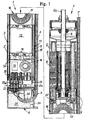
- the control device whose possible spatial arrangement in Fig. 1 This document shows in its housing the usual electronics, which is pressure-tightly encapsulated in this housing by means of solids.
- a major disadvantage of these known submersible motor units is that a material-appropriate disposal of non-usable submersible motor units or parts thereof can not be carried out economically. It takes a great deal of work and time, because the disassembly of the units is very cumbersome and thus causes high costs. There is a relatively small amount only a coarse separation, which must be done to that with numerous separation tools, or often no disassembly of the units instead. The resulting coarse parts or entire units are instead crushed in a shredder to the required level. The crushed mass is only partially reused and the remainder is given for disposal in a landfill. There environmental damage may occur because the electronic parts and the surrounding solids and potting compounds contain components that can enter into environmentally harmful compounds with the soil or other substances of the landfill. Legal regulations for environmentally friendly disposal are often bypassed for cost reasons.
- the state of the art described only permits limited economic repair of the submersible motor units from the point of view of avoiding environmentally harmful waste.
- the common housing for the motor and the control device must be destroyed mostly and not repairable itself, so that thereby additional costs incurred by a new common housing.
- the control device for the engine is essentially not inexpensive to repair because their electronic parts for stability reasons for their own housing, which itself must be irreparably destroyed, are surrounded by solids and / or potting compounds.
- the cooling of the electrical control device for the engine is not satisfactory, because the costs incurred by the electrical control device and in particular by their highly heat-generating components heat can be dissipated only at high excess temperature.
- the object of the invention is to improve a submersible motor unit of the kind initially stated in that the unit can be economically disposed of and repaired from the viewpoint of avoiding environmental pollution and improved in terms of cooling and dimensional stability.
- the submersible motor unit can be disposed of and repaired economically, because the modular units such as in particular the drive motor and the electrical control device can be dismantled quickly with minimal effort and in turn easily broken down into types of material and, where appropriate, replaced after replacing defective components, modules or other parts time and cost saving.
- the modular units such as in particular the drive motor and the electrical control device can be dismantled quickly with minimal effort and in turn easily broken down into types of material and, where appropriate, replaced after replacing defective components, modules or other parts time and cost saving.
- an improved repairability of the submersible motor unit is ensured and in terms of disposal, only those parts need to be disposed of that have irreparable damage. It is possible to provide improved material separation of defective parts or modules so that recovered raw materials can be recovered from the replaced materials, thereby saving primary raw material and avoiding or minimizing landfill and environmental impact.
- the submersible motor unit is thus more rigid and the common housing can consist throughout of the modular units drive motor and electrical control device of a single tubular body with relatively thin wall thickness.
- the dimensionally stable cartridge-shaped assembly allows safe transporting in Their contained, sensitive electronic components during the manufacture of the submersible unit.
- this has a Endsteckmaschine, which is already provided with the connecting cable. This allows a very quick replacement of a defective connection cable.
- the housing of the electrical control device comprises a tubular heat-conducting central unit for receiving the usual electrical control switching means and two detachably connected thereto end units each having an axial electrical plug formation, wherein the plug configurations of both end units in complementary electrical plug configurations of the engine and the Engage end plug-in unit.
- a control device is to be quickly connected to adjacent module units or to be separated therefrom and further provided within the housing of the control device control switching means for the purpose of replacement and / or disposal are quickly accessible. After replacement of defective components, the housing itself can be reassembled.
- the housing peripheral wall of the electrical control device forming center unit comprises at least one releasably secured, in cross-section semicircular shell part which extends over the entire length of the center unit and is formed radially elastic.
- the radially elastic design of the shell part can be achieved for example via longitudinal corrugations. In this way, a radially outwardly acting contact force of the housing of the control device is achieved to the common housing when the electrical control device in the form the cartridge-shaped assembly is inserted into the common housing.
- larger tolerances can be selected in the production, but it is ensured that the housing of the control device rests against the common housing, because the slightly compressed housing of the control device presses after insertion into the common housing radially outward. This ensures in a simple manner that the heat transfer from the housing of the control device takes place optimally on the common housing.
- this comprises a extending in its longitudinal center, removable board, which is provided with the usual electrical switching means, and further heat dissipation means are provided to dissipate the heat loss from the electronic parts of the board.
- the heat dissipation means may consist of elastically deformable pads which are clamped between the electronics and the housing of the center unit.
- the heat dissipation means can also consist of a metal block whose outer region partially forms the housing of the electrical control device.
- the heat dissipation means can be used sparingly because they need only be provided where heat must be dissipated. Casting compounds and free-flowing solids to fill cavities of the cartridge-shaped unit are no longer necessary.
- submersible motor unit comprises, in modular units, an electric drive motor 2, an electrical control device 3 for adjusting the speed and / or torque of the motor 2 and an electrical end plug 4, wherein the motor and the control means in a common, tubular and heat conductive housing 5 are housed.
- the drive motor drives with its shaft 6 to a centrifugal pump (not shown), which is coupled to the protruding end 6a of the shaft 6 in a known manner.
- the Endstecktician 4 is electrically connected to an unshielded cable 7, which extends on the outside of the common housing 5 and is optionally releasably secured thereto by suitable means. Instead of the unit 4, the cable 7 is also electrically connected directly to the device 3.
- the drive motor 2 is, for example, a wet-running motor in the form of a canned motor, so that the rotor of the motor is cooled in a known manner by a liquid.
- the stator 8 of the motor 2 does not flow around the motor liquid directly, but rests against the outer circumference of its sheet metal pact on the common housing 5 and is thus cooled in the usual way by the external liquid into which the submersible motor unit is immersed.
- the drive motor 2 may be an AC motor, in which case the control device 3 is a so-called frequency converter.
- the motor 2 may also be an electronically commutated DC motor, in which case the control device 3 is provided with the appropriate electronic equipment, which is known per se, to control the engine in terms of its speed and / or its torque.
- the control device 3 is provided with the appropriate electronic equipment, which is known per se, to control the engine in terms of its speed and / or its torque.
- Such a motor is in the embodiment according to Fig. 1 shown.
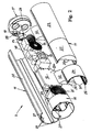
- the control unit 3 used for this motor is designed as a cartridge-shaped unit, which at one end with the drive motor 2, as shown in FIG Fig. 4 , is best seen, and at its other end with the Endsteckiki 4 is electrically plug-connected.
- the cartridge-shaped structural unit has an outer diameter which corresponds to the inner diameter of the common housing 5. After its axial insertion into the common housing, the cartridge-shaped unit comes with its outer peripheral surface 9 on the inner peripheral surface 10 of the common housing 5 to the system, so that the unit can dissipate heat generated in her directly to the common housing.
- the housing of the electrical control device 3 consists of a tubular, heat-conducting, multi-part center unit 11 having in its interior the usual electrical and / or electronic control switching means 12-15, and of two detachably connected to the center unit 11 end units 16 and
- both the motor 2 and the end plug 4 have a plug formation 20 or 21, which are respectively formed to the corresponding plug-in formations 18 and 19 of the device 3, complementary.
- the center unit 11 consists of several parts 22, 23, 24 and 25, which are predominantly formed as shell parts and have a semicircular cross-section. How out Fig. 2 it can be seen, the shell portion 22 extends over the entire length of the center unit 11, while the other half of the center unit 11 consists of the two shell parts 23 and 24 and at least one metal block 25, which also has a different function in addition to its function as a housing wall , as will become clear.
- the housing parts 22 to 25 are detachably connected to one another via latching means 26, 27 in the form of a groove and a cheek engaging therein.
- end plug-in units 16 and 17 are releasably connected to the center unit 11, for example via rib portions 28, which are frictionally connected to the shell parts 22, 23 and 24, or also via latching means or other types of connection, as will be readily understood by those skilled in the art.
- the center unit 11 is further formed slightly elastic in the radial direction, so that the cartridge-shaped assembly mounted control device 3 is radially flexible and radially inwardly can be slightly compressed. Since the outer diameter of the center unit is slightly larger than the inner diameter of the common housing 5 before inserting the assembly in the common housing, it is ensured that after insertion of the assembly, the outer peripheral surface of the center unit with a certain pressure on the inner peripheral surface of the common housing, to ensure optimum heat transfer.
- the procedure may be such that the shell part 22 has on its circumference a plurality of beads 29 which extend over the length of the shell part 22, as it Fig. 2 below shows.
- the parts 22 to 25 are made of thermally conductive material, such as aluminum.
- the central unit also has a removable in its longitudinal center, removable board 30, which is provided with the usual electrical and / or electronic switching and control means 12 to 15 substantially.
- the parts 23, 24 and 25 may be provided with two diametrically opposed grooves 31 into which the assembled board is inserted. In this way, the entire board is easily interchangeable.
- the heat dissipation means may also comprise at least one metal block whose outer region partially forms the housing of the center unit 11.
- the already mentioned component 25 can take over this function as it is Fig. 2 evident.
- the electronic component 12 of the board generates a lot of heat loss and therefore rests with its entire upper surface 12a on the inner surface 25a of the one- or multi-part metal block 25, so that the loss of heat is discharged directly from the block 25 to the common housing 5.
- the spaced apart position of the heating means 25 and 32 in particular that of approximately disposed in the central region of the central unit 11 metal block 25, protects the drive motor 2 in a particularly effective manner against the heat loss of the electrical and electronic components 12 - 15 and heat effects of sludge in the the submersible unit could be submerged with its lower portion during its operation.
- the end plug unit 4 comprises a housing 33 made of a bottom part 33a and a lid part 33b.
- the bottom part is provided with the plug-in training 21, the electrically conductive sockets are connected to the wires of the external electrical cable 7.
- the housing 33 further includes a side entrance 34 for the outdoor cable.
- the housing is further filled with a potting compound 35 to set the cable 7 positioned kinked in the housing and seal liquid-tight to the outside.
- the bottom part 33a has a support 36 which also ensures a desired deflection radius of the cable 7 entering the housing 33.
- An advantageous embodiment of the unshielded connection cable 7 of the Endstecktician 4 is to form this cable as a flat cable, so that it only slightly increases the outer diameter of the submersible motor unit.
- Fig. 1 shows the common housing 5 is liquid-tightly connected at its motor remote end with a bottom wall 5a, and this bottom wall has a sleeve 5b, in which the plug pins 19a of the plug formation 19 of the electrical control device 3 protrude.
- the Endstecktician 4 is inserted with its Endsteck property 21 in the sleeve 5b and thus establishes the electrical contact with the plug formation 19 of the device 3 ago.
- the bottom part 33a of the unit 4 is provided with a sealing means 37, for example in the form of an elastic plate.
Landscapes
- Engineering & Computer Science (AREA)
- Power Engineering (AREA)
- Microelectronics & Electronic Packaging (AREA)
- Structures Of Non-Positive Displacement Pumps (AREA)
- Motor Or Generator Frames (AREA)
- Control Of Non-Positive-Displacement Pumps (AREA)
Claims (12)
- Unité moteur submersible pour une pompe centrifuge, comprenant un moteur d'entraînement électrique (2), un dispositif de commande électrique (3) pour le réglage de la vitesse et/ou du couple de rotation du moteur, un carter (5) conducteur de chaleur, commun au moteur et au dispositif de commande ainsi qu'un câble de raccordement (7) raccordé électriquement au dispositif de commande, ce dispositif (3) étant prévu sur le côté d'extrémité du moteur opposé à la pompe, caractérisé en ce que le dispositif de commande électrique (3) est conçu en tant qu'ensemble en forme de cartouche apte à être inséré dans le carter commun (5) et à être raccordé électriquement par enfichage au moteur d'entraînement (2), en ce que l'enveloppe (11) du dispositif de commande (3) repose par sa surface périphérique extérieure (9) sur la surface périphérique intérieure (10) du carter commun (5) de telle sorte que l'ensemble en forme de cartouche peut évacuer la chaleur perdue générée à l'intérieur de celui-ci directement vers le carter commun et en ce que le dispositif de commande électrique est relié électriquement, au niveau de son extrémité opposée au moteur, à un câble de raccordement non blindé (7).
- Unité moteur submersible selon la revendication 1, caractérisée en ce que le câble de raccordement non blindé (7) est raccordé à une unité enfichable d'extrémité (4), elle-même raccordée par enfichage au dispositif de commande (3).
- Unité moteur submersible selon la revendication 1 ou 2, caractérisée en ce que l'enveloppe du dispositif de commande électrique présente une unité centrale (11) tubulaire conductrice de chaleur, destinée à recevoir les moyens commutateurs de commande électriques et/ou électroniques usuels (12 - 15), et deux unités d'extrémité (16, 17) qui y sont reliées de façon amovible et sont dotées respectivement d'une configuration enfichable (18, 19) électrique axiale, et en ce que les configurations enfichables des deux unités d'extrémité viennent s'emboîter dans des configurations enfichables électriques (20, 21) complémentaires du moteur (2) et de l'unité enfichable d'extrémité (3).
- Unité moteur submersible selon la revendication 1, 2 ou 3, caractérisée en ce que l'unité centrale (11) formant une paroi périphérique d'enveloppe du dispositif de commande électrique (3) comprend au moins une partie en coquille (22) fixée de façon amovible, qui s'étend sur toute la longueur de l'unité centrale et est réalisée de manière radialement élastique pour créer une force d'appui, agissant radialement vers l'extérieur, de l'unité centrale sur le carter commun (5) lorsque l'ensemble en forme de cartouche y est inséré.
- Unité moteur submersible selon la revendication 4, caractérisée en ce que la configuration radialement élastique de la partie en coquille (22) est constituée de moulures s'étendant sur sa longueur.
- Unité moteur submersible selon la revendication 3 ou 4, caractérisée en ce que l'unité centrale (11) présente une platine (30) démontable s'étendant le long de son axe longitudinal, dotée des moyens commutateurs de commande électriques et/ou électroniques usuels (12 - 15), et en ce que des moyens de dissipation de chaleur (32, 25) interchangeables sont prévus pour évacuer la chaleur perdue depuis les parties de la platine générant de la chaleur vers l'unité centrale (11).
- Unité moteur submersible selon la revendication 6, caractérisée en ce que les moyens de dissipation de chaleur sont constitués de coussins (32) élastiques reposant sur les parties de la platine (30) générant de la chaleur et qui sont coincées entre ces parties et l'unité centrale (11).
- Unité moteur submersible selon la revendication 7, caractérisée en ce que les coussins sont collés sur l'unité centrale (11) du dispositif de commande (3).
- Unité moteur submersible selon la revendication 6, caractérisée en ce que les moyens de dissipation de chaleur comprennent au moins un bloc métallique (25) dont une partie de région extérieure forme partiellement l'enveloppe de l'unité centrale (11).
- Unité moteur submersible selon l'une des revendications 2 à 9, caractérisée en ce que l'unité enfichable d'extrémité (4) comprend un boîtier (33) pourvu d'une entrée latérale (34) pour le câble de raccordement (7) et d'une masse de scellement (35) prévue à l'intérieur pour le positionnement sans angle aigu du câble et pour l'étanchéisation du câble vis-à-vis de liquides dans l'unité enfichable d'extrémité.
- Unité moteur submersible selon la revendication 10, caractérisée en ce qu'est prévu à l'intérieur du boîtier (33) de l'unité enfichable d'extrémité (4) un support (36) permettant une déviation sans angle aigu du câble de raccordement (7).
- Unité moteur submersible selon l'une des revendications 1 à 11, caractérisée en ce que le câble de raccordement électrique (7) est un câble plat.
Applications Claiming Priority (2)
| Application Number | Priority Date | Filing Date | Title |
|---|---|---|---|
| DE19727202 | 1997-06-26 | ||
| DE19727202A DE19727202A1 (de) | 1997-06-26 | 1997-06-26 | Tauchmotoreinheit |
Publications (3)
| Publication Number | Publication Date |
|---|---|
| EP0887907A2 EP0887907A2 (fr) | 1998-12-30 |
| EP0887907A3 EP0887907A3 (fr) | 2000-04-26 |
| EP0887907B1 true EP0887907B1 (fr) | 2011-03-09 |
Family
ID=7833749
Family Applications (1)
| Application Number | Title | Priority Date | Filing Date |
|---|---|---|---|
| EP98110878A Expired - Lifetime EP0887907B1 (fr) | 1997-06-26 | 1998-06-15 | Unité moteur submersible |
Country Status (3)
| Country | Link |
|---|---|
| US (1) | US6022196A (fr) |
| EP (1) | EP0887907B1 (fr) |
| DE (2) | DE19727202A1 (fr) |
Cited By (1)
| Publication number | Priority date | Publication date | Assignee | Title |
|---|---|---|---|---|
| DE102016009400A1 (de) * | 2016-08-02 | 2018-02-08 | Hydac Fluidtechnik Gmbh | Verfahren zum Herstellen einer spritzwassergeschützten elektrischen Kabel-Anschlussverbindung |
Families Citing this family (23)
| Publication number | Priority date | Publication date | Assignee | Title |
|---|---|---|---|---|
| FR2790519B1 (fr) * | 1999-03-05 | 2001-05-18 | Ksb Sa | Groupe motopompe submersible a circuit de demarrage integre |
| DE10010919A1 (de) * | 2000-03-06 | 2001-09-20 | Grundfos As | Frequenzumrichter |
| DE10010961A1 (de) | 2000-03-06 | 2001-09-20 | Grundfos As | Motorbaueinheit für ein Tauchpumpenaggregat |
| IT1315419B1 (it) * | 2000-04-11 | 2003-02-10 | Coverco Spa | Struttura di motore monofase particolarmente per pompe sommerse. |
| US6398521B1 (en) | 2001-01-30 | 2002-06-04 | Sta-Rite Industries, Inc. | Adapter for motor and fluid pump |
| FR2841702B1 (fr) * | 2002-06-27 | 2004-09-10 | Somfy | Actionneur electrique muni d'une piece de connexion |
| US20060034717A1 (en) * | 2004-08-13 | 2006-02-16 | Joseph Castellone | Wet rotor circulators |
| US7091638B2 (en) * | 2004-10-14 | 2006-08-15 | Pentair Pump Group, Inc. | Modular end bell construction for a submersible motor unit |
| SE529217C2 (sv) * | 2005-05-20 | 2007-06-05 | Atlas Copco Tools Ab | Momentberoende utlösningskoppling för en skruvdragare |
| JP4569428B2 (ja) * | 2005-09-12 | 2010-10-27 | 株式会社デンソー | 液晶表示装置 |
| FR2891413B1 (fr) * | 2005-09-28 | 2008-02-08 | Fp2X Groupement D Interet Econ | Dispositif de moteur electrique tubulaire |
| FR2891415B1 (fr) * | 2005-09-28 | 2011-08-12 | Fp2X | Ensemble de commande electronique pour un dispositif de moteur electrique tubulaire |
| DE102006036493A1 (de) * | 2006-08-04 | 2008-02-21 | Oerlikon Leybold Vacuum Gmbh | Vakuumpumpe |
| US20080286134A1 (en) * | 2007-05-16 | 2008-11-20 | Steven Regalado | Submersible pumping systems and methods for deep well applications |
| US8760089B2 (en) * | 2009-11-30 | 2014-06-24 | Franklin Electric Company, Inc. | Variable speed drive system |
| DE102010026231A1 (de) * | 2010-07-06 | 2012-01-12 | Andritz Ritz Gmbh | Unterwasserantriebseinheit für Offshore-Einsatz mit Hochspannungsgleichstromversorgung sowie Unterwasserantriebssystem |
| US20120126728A1 (en) * | 2010-11-19 | 2012-05-24 | El-Refaie Ayman Mohamed Fawzi | Integrated electric machine and silicon carbide power converter assembly and method of making same |
| US9780716B2 (en) | 2010-11-19 | 2017-10-03 | General Electric Company | High power-density, high back emf permanent magnet machine and method of making same |
| US8664903B2 (en) | 2011-06-27 | 2014-03-04 | Franklin Electric Company, Inc. | Adaptive flux control drive |
| RU2521532C2 (ru) * | 2012-08-21 | 2014-06-27 | Общество с ограниченной ответственностью "Нефтегазовые космические технологии" | Погружной электронный блок для погружного электродвигателя |
| DE102014116242A1 (de) * | 2014-11-07 | 2016-05-12 | Uts Biogastechnik Gmbh | Rühreinrichtung für einen Fermenter einer Biogasanlage |
| JP7043393B2 (ja) | 2015-09-03 | 2022-03-29 | フルイド ハンドリング リミティド ライアビリティ カンパニー | 水中ポンプの保守性を向上させる水中ポンプモータハウジング |
| DE102017101739A1 (de) * | 2017-01-30 | 2018-08-02 | Ebm-Papst St. Georgen Gmbh & Co. Kg | Baukastensystem |
Family Cites Families (11)
| Publication number | Priority date | Publication date | Assignee | Title |
|---|---|---|---|---|
| DE3642727A1 (de) | 1986-12-13 | 1988-06-23 | Grundfos Int | Unterwasser-motorpumpe |
| US4930997A (en) * | 1987-08-19 | 1990-06-05 | Bennett Alan N | Portable medical suction device |
| US5025185A (en) * | 1988-06-07 | 1991-06-18 | Aquaria, Inc. | Bubble trap for epoxy sealant in a submersible electric motor |
| DE3820003A1 (de) | 1988-06-11 | 1989-12-21 | Grundfos Int | Tauchpumpenaggregat |
| DE3828512A1 (de) * | 1988-08-23 | 1990-03-08 | Grundfos Int | Tauchpumpenaggregat |
| JPH078877Y2 (ja) * | 1989-03-07 | 1995-03-06 | 株式会社荏原製作所 | 水中ポンプ用制御装置 |
| US5028212A (en) * | 1989-09-26 | 1991-07-02 | Brophey Robert W | Method and apparatus for removal of floating immiscible liquids |
| DE4120665A1 (de) * | 1991-06-22 | 1992-12-24 | Teves Gmbh Alfred | Elektromotorisch angetriebene hydraulikpumpe |
| DE4317497A1 (de) * | 1993-05-26 | 1994-12-01 | Kabelmetal Electro Gmbh | Verfahren zur Herstellung längswasserdichter Kabel |
| DE19620901C1 (de) * | 1996-05-23 | 1997-08-21 | Grundfos As | Tauchmotor zum Antrieb einer Kreiselpumpe |
| US5763973A (en) * | 1996-10-30 | 1998-06-09 | Imo Industries, Inc. | Composite barrier can for a magnetic coupling |
-
1997
- 1997-06-26 DE DE19727202A patent/DE19727202A1/de not_active Withdrawn
-
1998
- 1998-06-15 DE DE59814484T patent/DE59814484D1/de not_active Expired - Lifetime
- 1998-06-15 EP EP98110878A patent/EP0887907B1/fr not_active Expired - Lifetime
- 1998-06-23 US US09/102,783 patent/US6022196A/en not_active Expired - Lifetime
Non-Patent Citations (1)
| Title |
|---|
| None * |
Cited By (1)
| Publication number | Priority date | Publication date | Assignee | Title |
|---|---|---|---|---|
| DE102016009400A1 (de) * | 2016-08-02 | 2018-02-08 | Hydac Fluidtechnik Gmbh | Verfahren zum Herstellen einer spritzwassergeschützten elektrischen Kabel-Anschlussverbindung |
Also Published As
| Publication number | Publication date |
|---|---|
| DE59814484D1 (de) | 2011-04-21 |
| US6022196A (en) | 2000-02-08 |
| EP0887907A2 (fr) | 1998-12-30 |
| DE19727202A1 (de) | 1999-01-28 |
| EP0887907A3 (fr) | 2000-04-26 |
Similar Documents
| Publication | Publication Date | Title |
|---|---|---|
| EP0887907B1 (fr) | Unité moteur submersible | |
| DE4243044C2 (de) | Wechselrichter-Motorkombination | |
| EP2072828B1 (fr) | Pompe avec moteur électrique à rotor noyé | |
| EP3615364B1 (fr) | Ensemble accumulateur | |
| EP2607707B2 (fr) | Moteur électrique | |
| DE3642724A1 (de) | Elektromotor mit einem frequenzumrichter zur steuerung der motorbetriebsgroessen | |
| DE9416975U1 (de) | Elektrischer Radmotor | |
| DE4120665A1 (de) | Elektromotorisch angetriebene hydraulikpumpe | |
| EP2270961A2 (fr) | Moteur électrique avec convertisseur de fréquence | |
| DE102004013578A1 (de) | Antriebssystem mit elektrischen Leistungsgeräten | |
| DE102010041589A1 (de) | Gehäuseelement zur Aufnahme einer Leistungselektronik einer Elektromaschine, Gehäuse für eine Elektromaschine, Werkzeug zur Herstellung eines Gehäuseelementes sowie Verfahren zur Herstellung eines Gehäuses für eine Elektromaschine | |
| EP3504433A1 (fr) | Ensemble motopompe | |
| EP2398132A1 (fr) | Groupe motopompe | |
| DE10223529B4 (de) | Motor mit einer elektronischen Steuereinheit und Verfahren zum Herstellen desselben | |
| EP2750268B1 (fr) | Groupe motopompe | |
| WO2013092317A2 (fr) | Moteur électrique | |
| DE102007057839A1 (de) | Elektromotor für Fahrzeuge | |
| DE9415078U1 (de) | Feuchtigkeitsdicht geschlossenes Motor-Pumpen-Aggregat, insbesondere für eine Kraftfahrzeug-Antiblockier-Bremsvorrichtung | |
| DE102004037079A1 (de) | Elektrischer Kompaktantrieb | |
| DE102019109693B4 (de) | Antriebseinheit mit einer elektrischen Maschine und mit einer Steuereinheit | |
| DE29712033U1 (de) | Motor-Pumpen-Aggregat, insbesondere Kraftfahrzeug-Antiblockier-Bremsvorrichtung | |
| DE19956429A1 (de) | Elektromotor für insbesondere eine Kreiselpumpe | |
| DE19709778A1 (de) | Elektromotor-Pumpenaggregat | |
| DE102021210043A1 (de) | Pumpe, insbesondere Getriebeölpumpe mit modularem Aufbau | |
| DE102005016908B4 (de) | Elektromotor |
Legal Events
| Date | Code | Title | Description |
|---|---|---|---|
| PUAI | Public reference made under article 153(3) epc to a published international application that has entered the european phase |
Free format text: ORIGINAL CODE: 0009012 |
|
| AK | Designated contracting states |
Kind code of ref document: A2 Designated state(s): DE FR GB IT |
|
| AX | Request for extension of the european patent |
Free format text: AL;LT;LV;MK;RO;SI |
|
| PUAL | Search report despatched |
Free format text: ORIGINAL CODE: 0009013 |
|
| AK | Designated contracting states |
Kind code of ref document: A3 Designated state(s): AT BE CH CY DE DK ES FI FR GB GR IE IT LI LU MC NL PT SE |
|
| AX | Request for extension of the european patent |
Free format text: AL;LT;LV;MK;RO;SI |
|
| RIC1 | Information provided on ipc code assigned before grant |
Free format text: 7H 02K 5/132 A, 7H 02K 11/04 B, 7H 02K 5/22 B |
|
| 17P | Request for examination filed |
Effective date: 20000803 |
|
| AKX | Designation fees paid |
Free format text: DE FR GB IT |
|
| 17Q | First examination report despatched |
Effective date: 20061116 |
|
| GRAP | Despatch of communication of intention to grant a patent |
Free format text: ORIGINAL CODE: EPIDOSNIGR1 |
|
| GRAS | Grant fee paid |
Free format text: ORIGINAL CODE: EPIDOSNIGR3 |
|
| GRAA | (expected) grant |
Free format text: ORIGINAL CODE: 0009210 |
|
| AK | Designated contracting states |
Kind code of ref document: B1 Designated state(s): DE FR GB IT |
|
| REG | Reference to a national code |
Ref country code: GB Ref legal event code: FG4D Free format text: NOT ENGLISH |
|
| REF | Corresponds to: |
Ref document number: 59814484 Country of ref document: DE Date of ref document: 20110421 Kind code of ref document: P |
|
| REG | Reference to a national code |
Ref country code: DE Ref legal event code: R096 Ref document number: 59814484 Country of ref document: DE Effective date: 20110421 |
|
| PLBE | No opposition filed within time limit |
Free format text: ORIGINAL CODE: 0009261 |
|
| STAA | Information on the status of an ep patent application or granted ep patent |
Free format text: STATUS: NO OPPOSITION FILED WITHIN TIME LIMIT |
|
| 26N | No opposition filed |
Effective date: 20111212 |
|
| REG | Reference to a national code |
Ref country code: DE Ref legal event code: R097 Ref document number: 59814484 Country of ref document: DE Effective date: 20111212 |
|
| REG | Reference to a national code |
Ref country code: FR Ref legal event code: PLFP Year of fee payment: 19 |
|
| PGFP | Annual fee paid to national office [announced via postgrant information from national office to epo] |
Ref country code: DE Payment date: 20160622 Year of fee payment: 19 Ref country code: GB Payment date: 20160506 Year of fee payment: 19 |
|
| PGFP | Annual fee paid to national office [announced via postgrant information from national office to epo] |
Ref country code: IT Payment date: 20160504 Year of fee payment: 19 Ref country code: FR Payment date: 20160422 Year of fee payment: 19 |
|
| REG | Reference to a national code |
Ref country code: FR Ref legal event code: PLFP Year of fee payment: 20 |
|
| REG | Reference to a national code |
Ref country code: DE Ref legal event code: R119 Ref document number: 59814484 Country of ref document: DE |
|
| GBPC | Gb: european patent ceased through non-payment of renewal fee |
Effective date: 20170615 |
|
| REG | Reference to a national code |
Ref country code: FR Ref legal event code: ST Effective date: 20180228 |
|
| PG25 | Lapsed in a contracting state [announced via postgrant information from national office to epo] |
Ref country code: GB Free format text: LAPSE BECAUSE OF NON-PAYMENT OF DUE FEES Effective date: 20170615 Ref country code: DE Free format text: LAPSE BECAUSE OF NON-PAYMENT OF DUE FEES Effective date: 20180103 |
|
| PG25 | Lapsed in a contracting state [announced via postgrant information from national office to epo] |
Ref country code: FR Free format text: LAPSE BECAUSE OF NON-PAYMENT OF DUE FEES Effective date: 20170630 Ref country code: IT Free format text: LAPSE BECAUSE OF NON-PAYMENT OF DUE FEES Effective date: 20170615 |